Interface and Application Programming
write an application that interfaces with an input &/or output device that you made
The interface design with arduino
The interface design with attiny and grasshopper
compare as many tool options as possible
General
Processing is recommended by Neil because works similar to Arduino. But more basic is Scratch, but If I am going to use the sensor I programmed in Arduino I have to use the S4A which “is a Scratch modification that allows for simple programming of the Arduino open source hardware platform. It provides new blocks for managing sensors and actuators connected to Arduino. There is also a sensors report board similar to the PicoBoard one.” In the recommended list there are also the App Inventor developed in the MIT, which is “is an intuitive, visual programming environment that allows everyone – even children – to build fully functional apps for smart phones and tablets”. I can also use Python, highly recommended, but I will need a PySerial to talk to the port as well as an interface like Tkinker, as far as I understood.
individual assignment:
For this week we will make an interface
What I need
Software
· Arduino program
·
S4A
(Scratch for Arduino)
Hardware
· YL-69 humidity sensor
· Arduino 1
· Jumpers
write an application that interfaces with an input &/or output device that you made
First I have to order my ideas. Since I could not work properly the past two weeks, I have to make this assignment with Arduino first while I do the PCB boards and replace the Arduino.
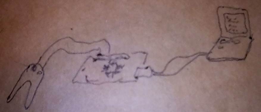
In the near future I will connect a soil humidity sensor to a pcb that will control a Solenoid valve and at the same time send the data and values captured to an application and Led´s that will tell you easily the moisture state of the plant
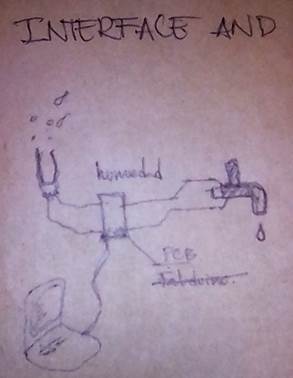
I will do everything on Arduino first to check that everything works. Then I will do the application with that, and finally do the pcb´s .
Sensor + Arduino + Interface
Connect the sensor to and Arduino board and send data to the Arduino program interface in the computer
Will follow the Arduino and Soil Moisture Sensor -Interfacing Tutorial
In this exercise I will interface the humidity sensor HL-69, that measures the water inside the soil. This sensor can be use as digital and analog. I will use the analog mode, because I can obtain a wide range of data.
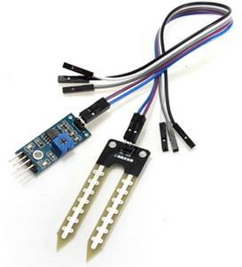
The two legs of the sensor transmit energy when the circuit is closed because of the presence of water that means that there is humidity in the soil. The range of current could be measure to get a range. “When there is more water, the soil will conduct more electricity”
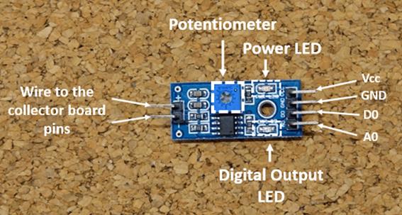
Specifications of the sensor
· Sensitivity is adjustable via the blue digital potentiometer
· Operating voltage 3.3V-5V
· Module dual output mode: digital output or analog output giving more accuracy
· Has pre-drilled hole for easy installation
· Small board PCB size: 3cm * 1.6cm
· Power indicator (red) and digital switching output indicator (green)
· Uses the LM393 comparator chip
· Signals and connections of the soil moisture sensor YL-69, FC-28 or HL-69
· VCC (5V) - connect to 3.3 V or 5V pin of Arduino board.
· GND (or G) - ground pin of Arduino board
· SIG - an analog signal out that can be attached to the ADC pin on any microcontroller. The value read on SIG will vary depending on the voltage with which you power the sensor
· D0 - Digital output to Arduino board
· A0 - Analog output to Arduino board
· The "A0", is a serial signal 0-5 volts that when fully dry it outputs 5 volts, when fully wet, 0 volts. The "D0", is configured with the trim pot and is brought high when the moisture level reaches a desired point.
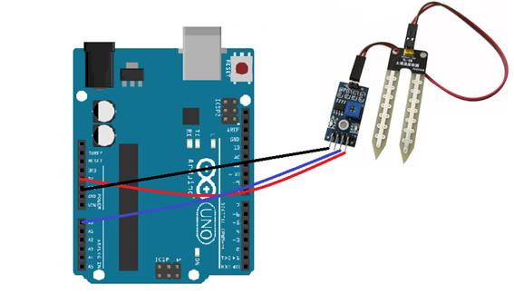
Circuit Diagram
· VCC of sensor to 5V of Arduino
· GND of sensor to GND of Arduino
· A0 of sensor to A0 of Arduino
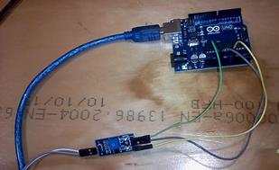
1.
Connect
and open Arduino in the computer
2. Copy the arduino code
int sensor_pin = A0;
int output_value ;
Serial.begin(9600);
Serial.println("Reading From the Sensor ...");
delay(2000);
}
void loop() {
output_value= analogRead(sensor_pin);
output_value = map(output_value,550,0,0,100);
Serial.print("Mositure : ");
Serial.print(output_value);
Serial.println("%");
delay(1000);
}
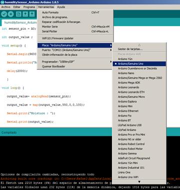
3. I was running the code but gave an error.
error: 'Serial' was not declared in this scope
Serial.begin(9600);
4.
That
was because on tools, the board was specified as other. I switched it to the
right one.
5. Now I can download the code to the Arduino
6. And it works
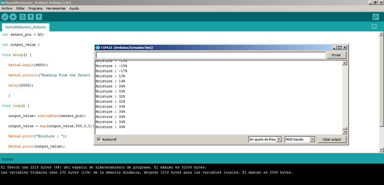
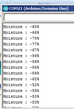
7. I see something is not right. The data also gives me negative values on percentage. I think when there is no humidity the vale should be 0%, not -100%
8.
I will
read the sensor with water and completely dry. These will be my maximum and
minimum.
Dry 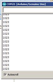 Under
water
Under
water 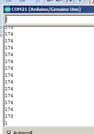
9. I changed the values in the Arduino program
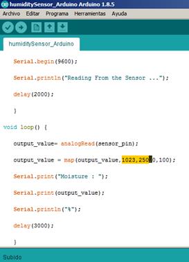
10.
And
now it works much better
Dry
plant 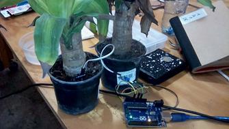
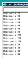 3% Moisture
Wet
plant 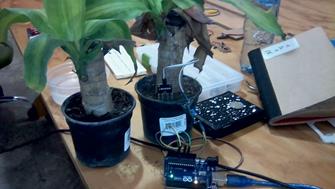
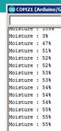 55% Moisture
The interface design with arduino
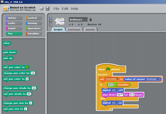
1. I selected the S4A. The scratch for Arduino.
2. For now I just want to turn on a red color on the screen when the humidity is from 0-30 which means is very dry, a green color when the humidity percentage is between 31and 60 percent that will mean that the plant is fine and a yellow color when the values are between 61 – 100% that means that the soil is over hydrated.
3. Download the S4A
4. Download our firmware
5. Open the arduino enviroment
6. Connect the arduino board
7. Open the firmware in Arduino
8.
Upload
it to the board
9.
I
watched this tutorial Scratch 4 Arduino Tutorial #5: Motion sensor PIR S4A. Here, we will see how to
detect motion using PIR motion sensor with Scratch 4
10. I adapted the block to my need about humidity and it goes like this
The led in the Arduino turns on where there is enough humidity and when there is not, a drum sound starts from the computer.
I set the minimum value to
turn off the led at 800, because I knew from the exercise before that my range
detected by the pin A0 is between 150 and 1023. I can change that vale
depending on how much humidity I think will be enough for the soil.
11.
I
added another interaction: A led button animation. And also find out how to put
a window with my camera. With the help of this tutorial Tutorial Blinking LED con Arduino y
S4A
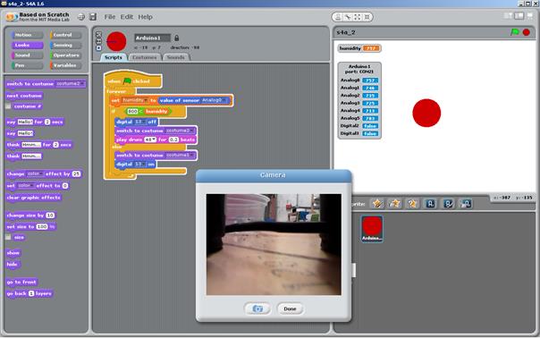
12. the video of my interface Humidity interface 1 and Humidity interface 2
The interface design with attiny and grasshopper
After understanding how to do an interface with Arduino, I did a new interface using my own board and grasshopper
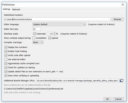
1. I used the board I did for the Electronic Design Assignment. First, I had to Burn the Bootloader to be able to program my ATtiny, but I didn’t have the board installed and it wasn’t available in the Board Manager. Therefore I had to go to the Arduino Forum and find the solution. To solve this I had to go to File / Preferences / Additional Boards Manager and paste the following URL: https://raw.githubusercontent.com/damellis/attiny/ide-1.6.x-boards-manager/package_damellis_attiny_index.json
Then I could see the ATtiny44 board. I chose Processor: “ATtinny44”, Clock “Internal 8 MHz” and Programmer: “Arduino as ISP” and did the Burn Bootloader. Finally I did the Bootloader.
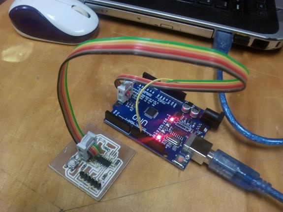
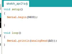
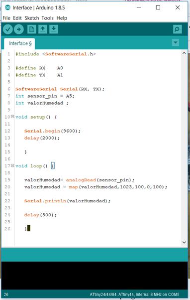
2. I did a simple program in Arduino for measuring my Soil Moisture Sensor and print the values in the Serial Monitor. For reading data from my board to the serial, I had to use the TX and RX pins from the FTDI and I had to connect my sensor to the AVR ISP. It took me a while to find out which pins were equivalent with the pins in arduino to do the program but this image helped me a lot.
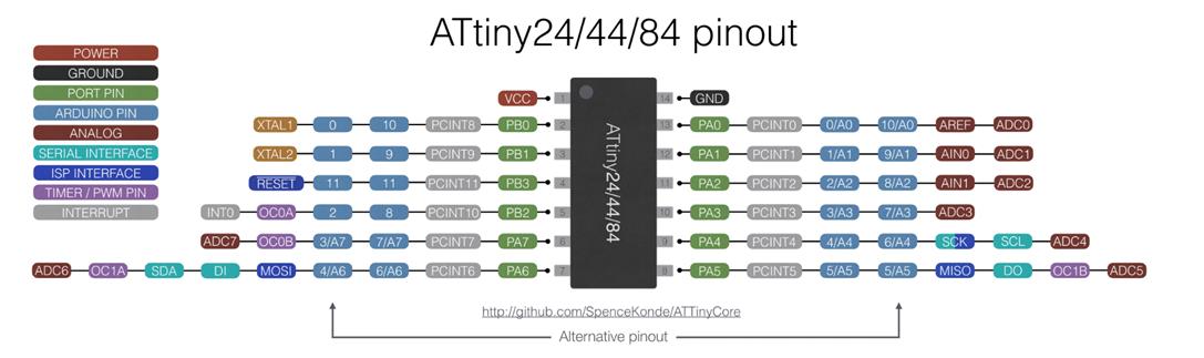
In conclusion my pins are these:
In the FTDI: RX - A0 and TX - A1 to connect to the serial.
In the AVR ISP: MISO - A5, VCC and GND.
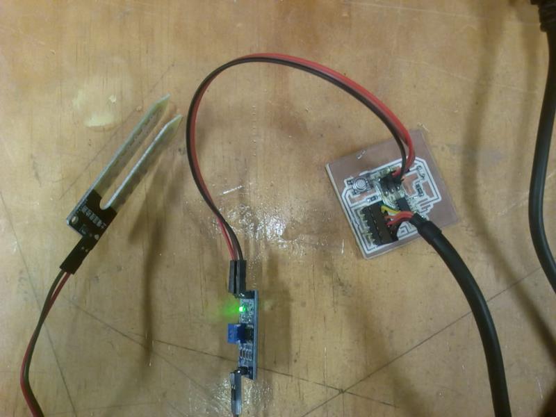
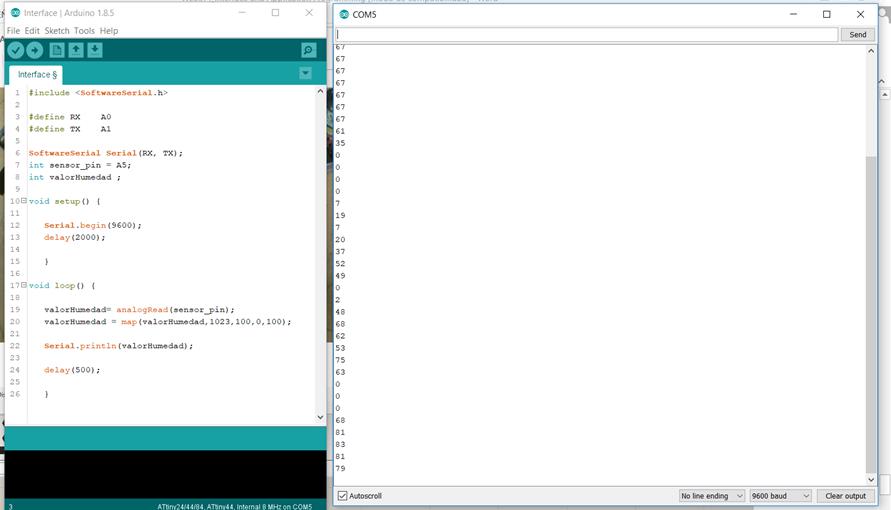
The program worked and I could read values. I mapped the values from 1023 – 100 to 0 – 100 to have a better control.
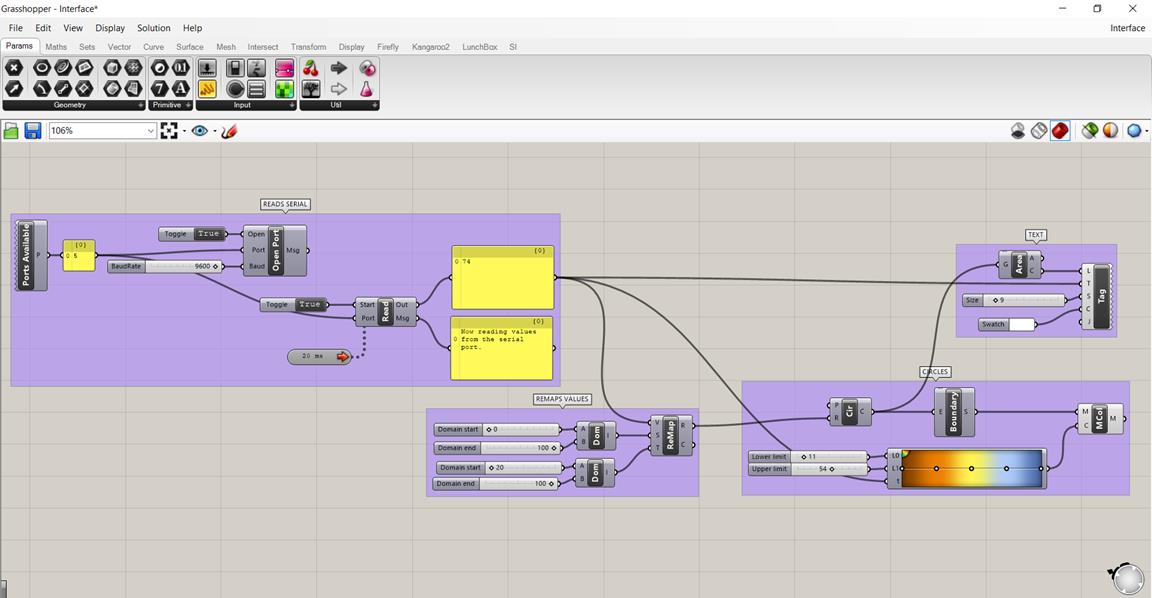
3. Once I was reading values from my board, I could do the interface. I decided to use Firefly (https://www.food4rhino.com/app/firefly), a plugin that communicates micro-controllers to Grasshopper, so that I could have a graphic visualization of my data.
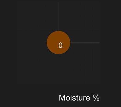
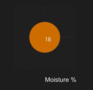
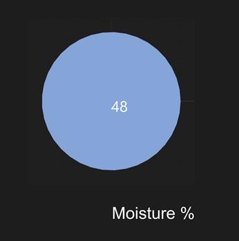
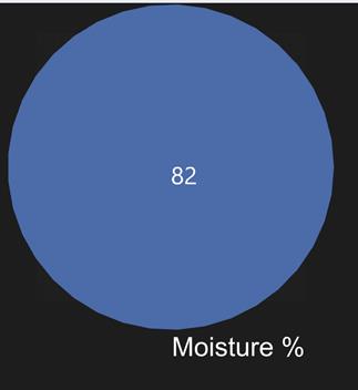
This is the definition I made. Firefly reads the serial and shows the values. I used those values as the measurement of the radius of a circle, so, the bigger the value, the bigger the circle. I also added a color gradient. When the circle gets orange, it means the level of moisture is low. When it gets blue, it means the level is high.
My Conclusions
· The Arduino monitor is also a basic interface that comes with the Arduino program. Allows you to print and list a series of value you define in this case by a sensor and transformed into a comprehensive range from o to 100%
· Scratch for Arduino reminds me to qbasic. I learn it when I was at school. When programming on that environment, which was by codes was similar in with this S4A in the conditions like “If”.
· I used Arduino as a board, but I will do the same with a PCB I am designing from the past weeks.
· S4A is a very friendly environment that also allows programming and interfacing the inputs and out puts in a comprehensive way.
· For my final project I consider more important an analog interaction between input and outputs, I mean play sounds and Leds in order to make the user know when a plant needs water, when the tank of water is full or even know there is enough sunlight to make electricity for the house. Probably the computer will be useful to measure the data and achieve it for future studies and also the Autonomous Device could be a resource station that measures the existing resources on a specific place.
· I have to know the maximum and minimum the sensor is measuring and define the range where is good or wrong according to the plant need in this case. Some plants need more water than others.
group
assignment:
compare as many tool options as possible
Download files / Descargar archivos