Week 4 / semana 4
cut something on the vinylcutter
design, lasercut, and document a parametric press-fit construction kit
group assignment:
characterize your lasercutter
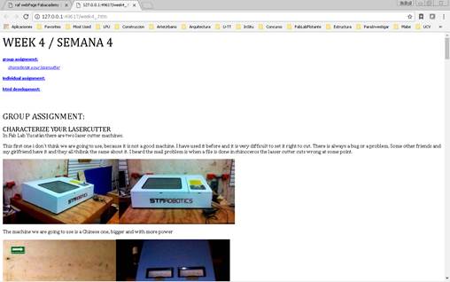
In Fab Lab Yucatán there are two laser cutter machines.
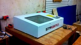
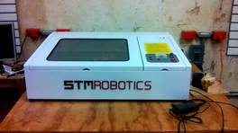
This first one i don´t think we are going to use, because it is not a good machine. I have used it before and it is very difficult to set it right to cut. There is always a bug or a problem. Some other friends and my girlfriend have it and they all think the same about it. I heard the mail problem is when a file is done in rhinoceros the lasser cutter cuts wrong at some point.
It is a Chinese machine that a Mexican vendor sells here. STM Robotics is Mexican company focus on selling machines for laser cutting, engraving and cnc routing. I didn´t find information about this machine in the web, because the seller doesn´t sell it any more due to the bad quality of the equipment. But I know it is 40watts power machine with a cutting surface of 40 x 40 cms
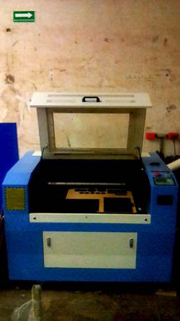
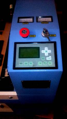
The machine we are going to use is a Chinese one, bigger and with more power. 100Watts and a fixable bed with a cutting surface of 40 x 90 cms
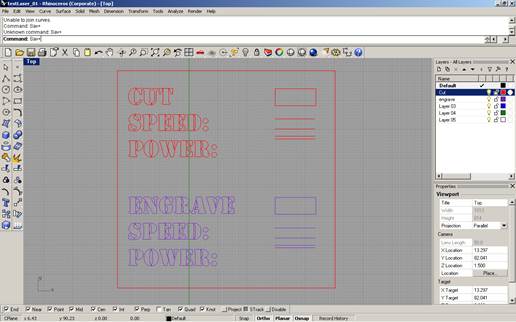
1. I did my test file on Rhinoceros. Just a square with cut and engrave. Each one in a different layer. The text must be exploded.
2. Save it as .dxf file in a USB
3. Go to the laptop that controls the machine. Is has to be connected by a USB cable to the laser cutter, and the USB key must be plugged to the laptop also.
4. Open the laser cutter program, right click and select open as administrator
5. Import the .dxf file from the USB
6. Set the parameter for cutting and engraving, speed and power for each one
7. On the menu, tools, select unite lines
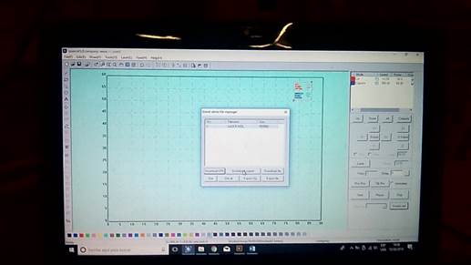
8. Select immediate or not if you want to set the area where is going to cut or use the coordinated straight from the program
9. Presses download, when the new window opens, delete all the files there and press download current. It will transmit the file to the laser cutter machine
10. The head of the laser should be more and less 15mm from the material. You need to measure it by yourself and move the bed up of down with the Z button.
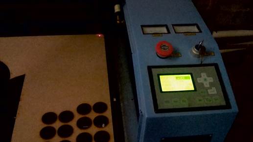
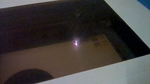
11. Press test to check the area that is going to be cut and the press start. It will start cutting
12.
Check
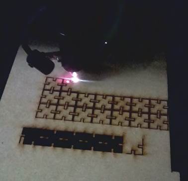
if it did cut. In my case it didn´t cut at the first glance, so I had to put
the speed slower and more powerful
https://youtu.be/C6WBlBGVq6I
13. On the third try it worked
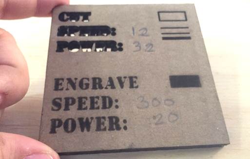
14. I try with different thickness of MDF. In this case the MDF is 3mm thick.
15. And finally with this
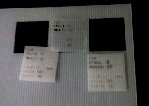
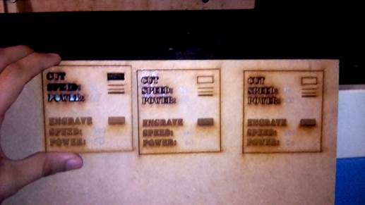
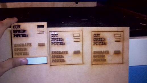
16. We continued cutting in different materials
cardboard
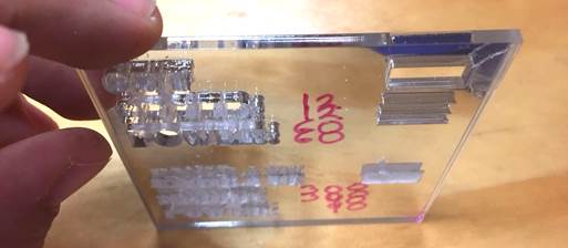
Acrylic
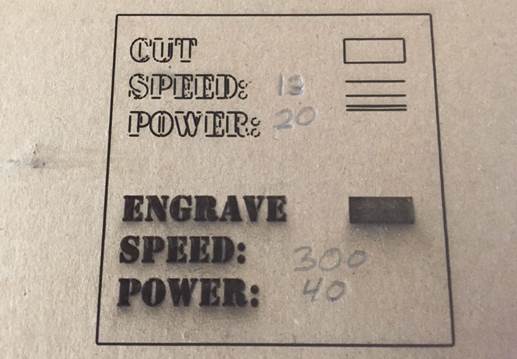
more cardboard
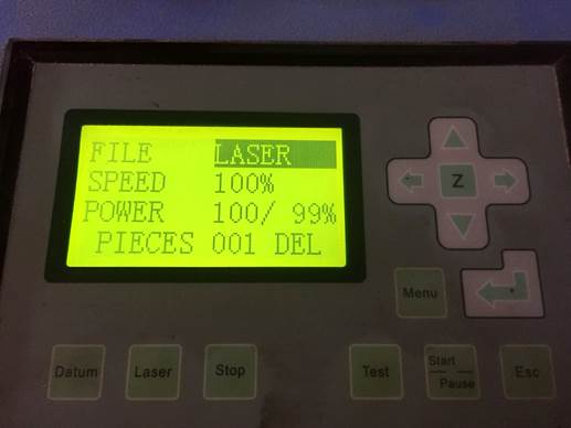
17. The laser always set at 100% because the other parameters are set from the computer
18. The table we have so far
is :
|
cut |
engrave |
||||
|
material |
thickness (mm) |
speed |
power |
speed |
power |
|
Mdf |
3 |
8 |
65 |
300 |
50 |
|
10 |
50 |
250 |
40 |
||
|
|
|
200 |
30 |
||
|
Mdf |
6 |
|
|
300 |
60 |
|
|
|
300 |
60 |
||
|
8 |
65 |
300 |
50 |
||
|
white cardboard |
6 |
15 |
30 |
300 |
40 |
|
10 |
45 |
300 |
40 |
||
|
12 |
40 |
200 |
40 |
||
|
Acrlylic |
6 |
12 |
60 |
388 |
18 |
|
Cardboard |
6 |
12 |
32 |
300 |
20 |
|
|
|
300 |
40 |
||
The strike numbers
are the values where the laser didn´t cut the material
Individual assignment:
cut something on the vinylcutter
1.
The Vinyl
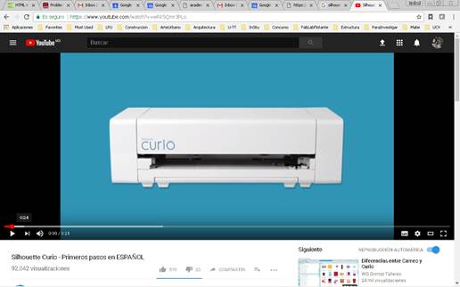
cutter I am going to use is a Silhouette Curio™
· Base of 8.5 x 6 inches
· Cutting surface of 8.5 x 6 inches
· Embossing de 8.5 x 6 pulgadas
· Regular cutting knife
· Fine relief tool
· Wide relief tool
· 50 exclusive digital designs
· AC power adapter
· USB Cable
· Software Silhouette Studio®
·
I
put a tutorial to know step by step how to use it
https://www.youtube.com/watch?v=wRk5Qmr3PLo
2. Connect the machine to your computer by USB
foto
1.Download
the software Silhouette Studio
https://www.silhouetteamerica.com/software
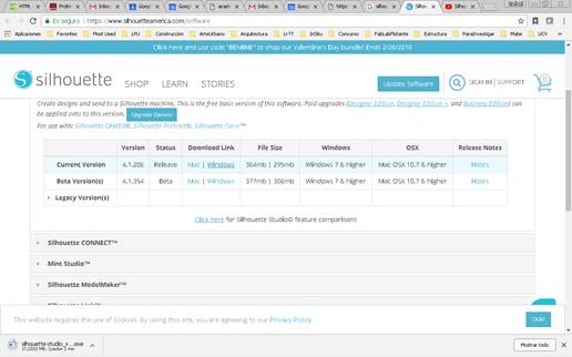
4. Install and open the program
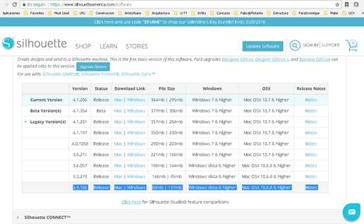
5. It didn´t work on my computer. Opens but the working area fusions with the background. Like in the past it is probably because my computer is old. So I saw in internet I can download the previous version on the same page but on Legacy Version
6. It didn´t work, so I am going to try on another computer
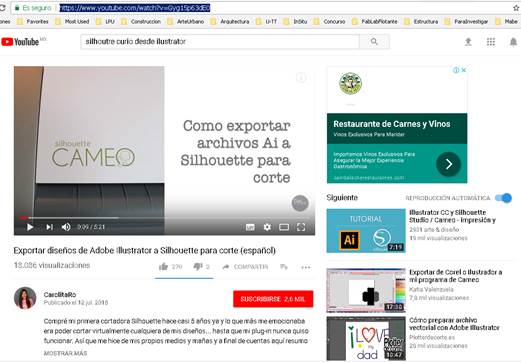
7.
I
did my designs in ilustrator, so I watched a tutorial to how to import .ai
files to the Silhouette Studio.
https://www.youtube.com/watch?v=Gyg15p63dE0
8. Here is what I want to cut on vinyl that I did on Ilustrator
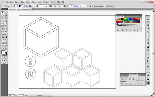
9. I put everything on lines and exported it to .dxf
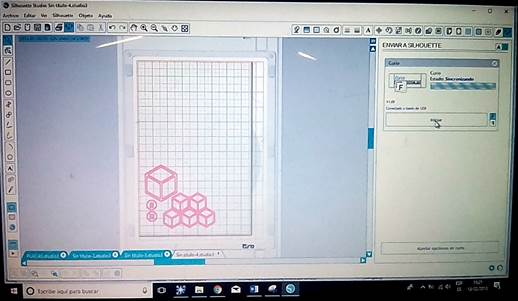
10. drag the file into the Silhouette Studio software
11. Scale and place the design in the page
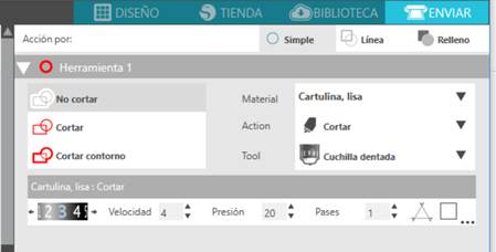
12. Send to cut. There, I adjusted the parameters for cutting. In Curio you can set the speed (velocidad) from 1 to 10 and the force (presión) from 1 to 33. You can also define how many times the blade passes (Pases).
I used Speed – 4.0, Force – 20 and only one pass.
13. The machine cut it
14. Three of the designs didn´t work. One because it cut the external line the figure came out. The other two because they were to small.
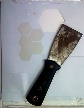
15. I used a spatula for peeling off the vinyl.
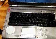
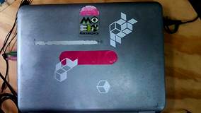
16. I pasted my designs in my laptop
design, lasercut, and document a parametric press-fit construction kit
I want to
keep doing parts for my final project. So I am going to cut assembly cubes
cutting mdf pieces with slots for the press-fit
1. My couple, which is a crack on digital fabrication send me a tutorial with a program to build cubes and other vectors files
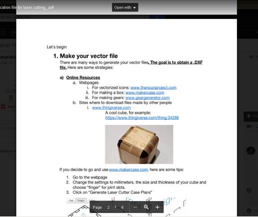
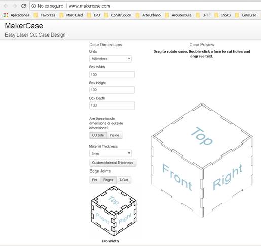
this is the
cube I want to do with the parameters
100 mm x 100 mm x 100 mm
3mm thickness material
finger joints
3. the result
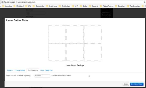
And you can
still there edit some parameters like margins, vector, text and kerf
4. Download plans as .svg
5. I opened the file and ilustrator and edited it adding one icon I create in the previous week
6. Saved the file as .dxf
7. When I opened the file in the laser cutter software it was to big, bigger than the cutting frame. There is a way to scale it, but I wasn´t sure how, because I needed to have the slots with 3mm thick. So I went back to the dxf file and opened in Rhinoceros where I specified the units of the file. Exported as .dxf again and went to the laser cutter software
8. Now it was in the right scale
9. Since I was going to use MDF 6mm thick, I knew already which parameters I needed to use.
|
cut |
engrave |
||||
|
Material |
thickness (mm) |
speed |
power |
speed |
power |
|
MDF |
6 |
8 |
65 |
300 |
50 |
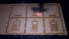
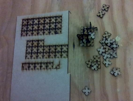
10. I cut the file
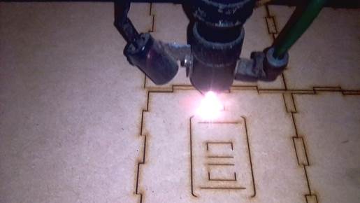
cutting
engraving
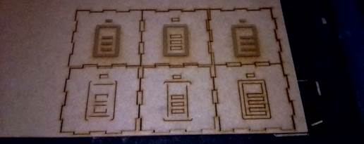
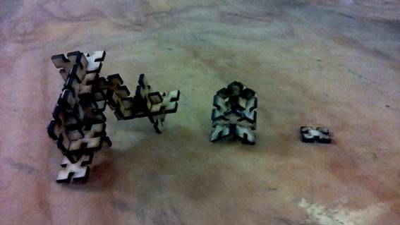
11. Assembled the cube
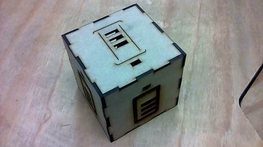
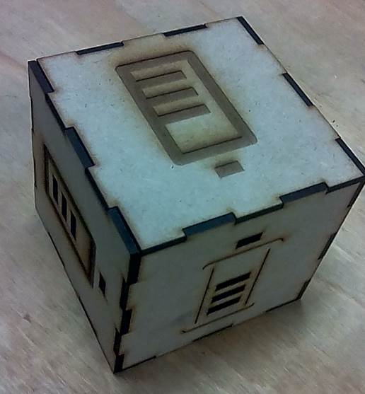
It was a little bit loose. So I have to learn more about the
kerf.
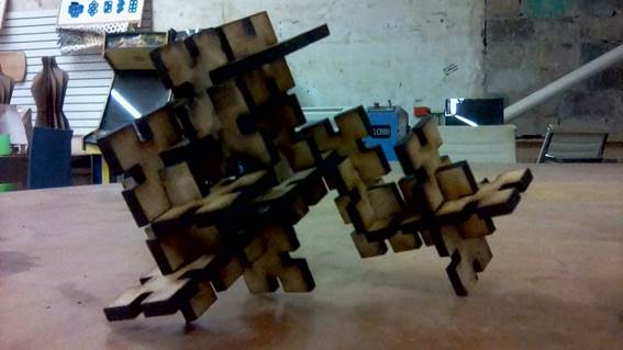
This can be only assembled in one. If I use grasshopper I can probably create a
piece than can be repeated and assembled in many ways. I have an idea that will
do later
In order to do my assignment properly, I will design trough a parametric process a press fit configuration.
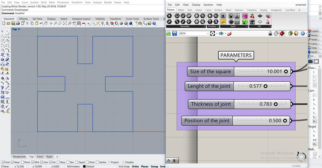
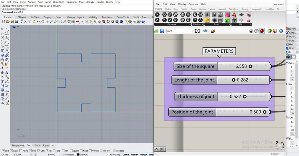
First I tried Grasshopper (http://www.grasshopper3d.com/) which is a graphical algorithm editor integrated with Rhinoceros. I have very basic knowledge of grasshopper so I went step by step and ask a girl that works in the Fab Lab when I got stuck. At the end I could made a parametric modular piece. With my definition you can modify the size of the shape (in this case a square), the thickness and the length of the joint (so you can adapt it to press-fit different materials) and the position of the joint.
This is the definition
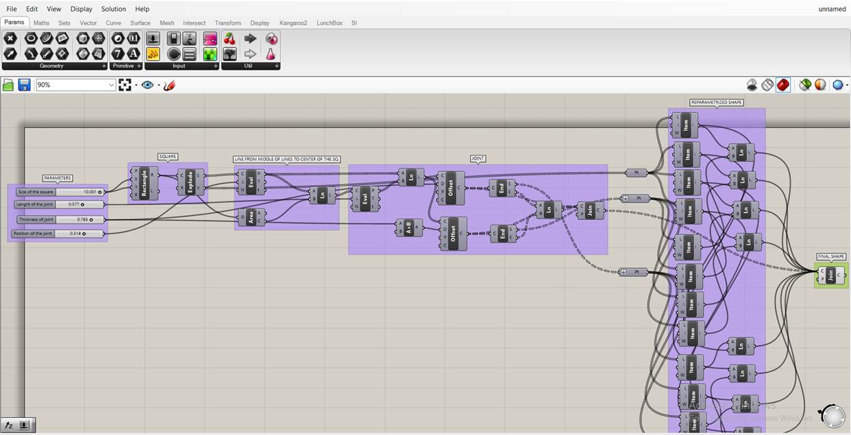
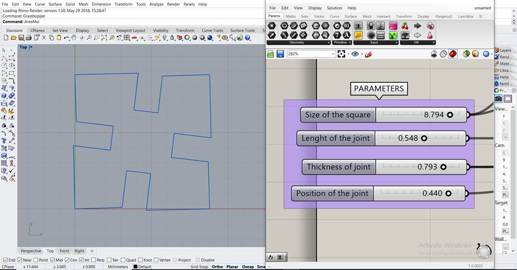
Here are some examples of how the piece changes when you modify the parameters.
Link to video:
Once I worked with the graphical interface of grasshopper, I wanted to understand how the script worked so I tested another program. Looking at previous Fab Academies I found an interesting one. Openscad is software for creating solid 3D CAD objects. I downloaded it from their web page http://www.openscad.org/.
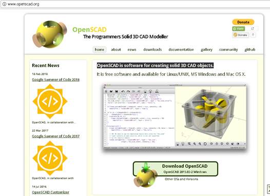
The interesting thing of Openscad is that it is a free software application for creating solid 3D CAD (computer-aided design) objects. It is a script-only based modeller that uses its own description language; parts can be previewed, but it cannot be interactively selected or modified by mouse in the 3D view. An OpenSCAD script specifies geometric primitives (such as spheres, boxes, cylinders, etc.) and defines how they are modified and combined. https://en.wikipedia.org/wiki/OpenSCAD
1. Opened the program
2. I search a definition as reference
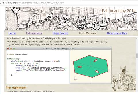
http://fabacademy.org/archives/2014/students/laverne.matthieu/Mod04.html
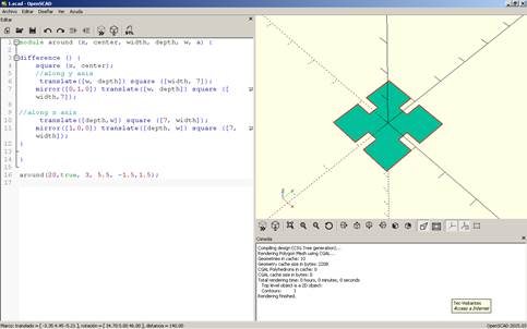
3. I did my own definition changing parameters and writing my own definition by myself.
The values highlighted in yellow are the ones I modified to change the thickness and length of the joint.
module around (x, center, width, depth, w, a) {
difference () {
square (x, center);
//along y axis
translate([w, depth]) square ([width, 7]);
mirror([0,1,0]) translate([w, depth]) square ([width,7]);
//along x axis
translate([depth,w]) square ([7, width]);
mirror([1,0,0]) translate([depth, w]) square ([7, width]);
}
}
around(20,true, 3, 5.5, -1.5,1.5);
4. This was the result of the script I wrote
5. I can change the parameter and obtain a different shape. I changed the value of two constants in order to make the subtracted square bigger. Below the image you can see the change highlighted
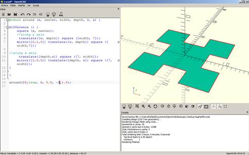
module around (x, center, width, depth, w, a) {
difference () {
square (x, center);
//along y axis
translate([w, depth]) square ([width, 7]);
mirror([0,1,0]) translate([w, depth]) square ([width,7]);
//along x axis
translate([depth,w]) square ([7, width]);
mirror([1,0,0]) translate([depth, w]) square ([7, width]);
}
}
around(20,true, 6, 5.5, -3,1.5);
6. Now I have to cut it in the laser
7. I exported it to dxf
8. Opened it in Rhinoceros to check the scale was right and also to copy the object
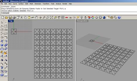
9.
Saved
the file again and ready to cut. It is set to be in any material 3mm width
Name of file: PressFitForReal.dxf
10. I laser cut the shape
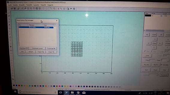
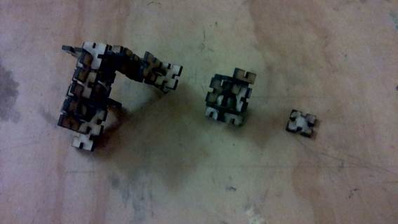
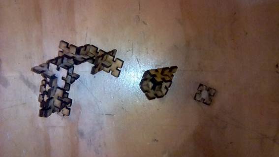
11.
Rodrigo,
one colleague of the Fab Lab, used the same shape for a project his is working
on
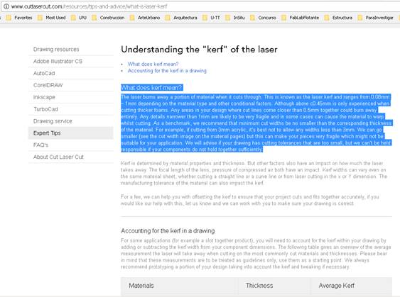
lasercutter kerf
I
found a good definition on
http://www.cutlasercut.com/resources/tips-and-advice/what-is-laser-kerf
What does kerf mean?
The laser burns away a portion of material when it cuts through. This is known as the laser kerf and ranges from 0.08mm – 1mm depending on the material type and other conditional factors. Although above c0.45mm is only experienced when cutting thicker foams. Any areas in your design where cut lines come closer than 0.5mm together could burn away entirely. Any details narrower than 1mm are likely to be very fragile and in some cases can cause the material to warp whilst cutting. As a benchmark, we recommend that minimum cut widths be no smaller than the corresponding thickness of the material. For example, if cutting from 3mm acrylic, it’s best not to allow any widths less than 3mm. We can go smaller (see the cut width image on the material pages) but this can make your pieces very fragile which might not be suitable for your application. We will advise if your drawing has cutting tolerances that are too small, but we can’t be held responsible if your components do not hold together sufficiently.
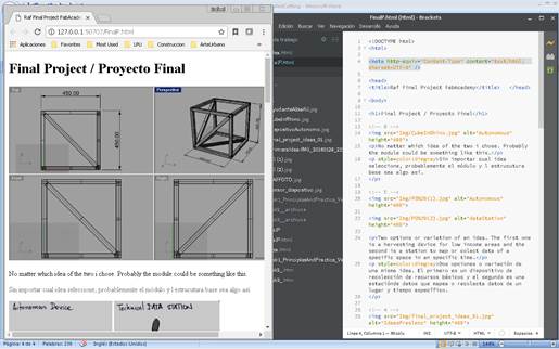
html development:
1. I had a problem in my web page, in Final Project. I am writing the texts in english and spanish. The accent and the ñ character were giving an error and not showing correctly. My tutors and Barcelona and here gave an option on a weppage
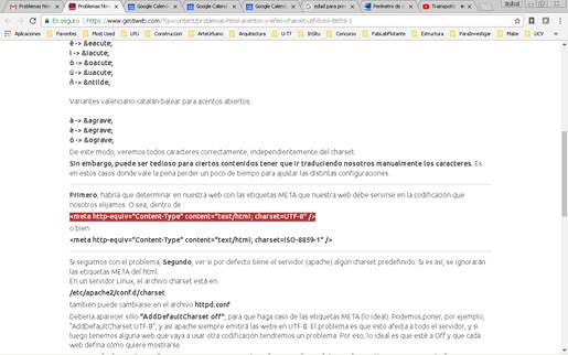
2.
To
write that command in my html file
<meta
http-equiv="Content-Type" content="text/html;
charset=UTF-8" />
3.
I did
that and the problem was aparently solved. Will se later when I do the push.
… and I cehcked later and it didn´t work.
4.
I
tried with another command in another web page recommended
https://www.w3schools.com/tags/att_meta_charset.asp
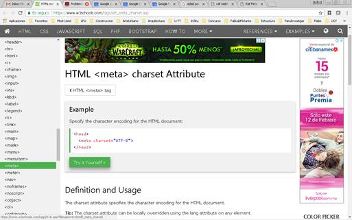
<meta charset="UTF-8">
5. I did the secuence to upload the page again and now it worked. My spanish characters look right.
Note: if the git bash is not working well, and the page is not uploading, try closing the program and opening it again and do the sequence of commands again.
The problem with the special characters is persisting in the pages exported from word. The way to solve it is:
1.
When
saving the document, on tolls on the button right, select the code for the web
page
I selected Unicode (UTF-8)
I also in fonts selected multilingual characters just in case
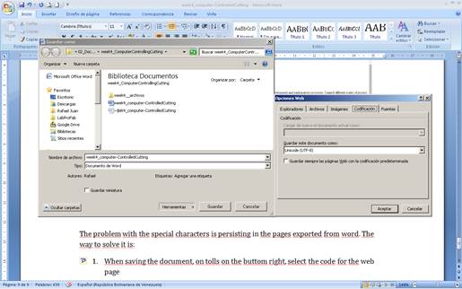
2. Now it worked
3.
4. Next i will solve the other documentation pages
Download files / Descargar archivos