OUTPUT DEVICES
In this assignment I have to run an output device to a microcontroller board that I will design.
The learning outcomes:
Demonstrate the workflows used in the design and manufacture of circuit boards
Implement and interpret programming protocols
Individual assignment
Add an output device to a microcontroller board you've designed, and program it to do something
First, what I'm looking for is to control the RGB led and a DC motor of a cell phone, two output devices that I want to control in 2 ways, The first way is on and off for each one, the second way to modify the speed and value of the led brightness.
I'm going to leave the entrance for the ftdi with what purpose, well in order to be able to communicate with me input board. I know that it is not part of this assigment, but I wanted to try something extra.
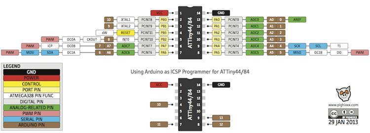
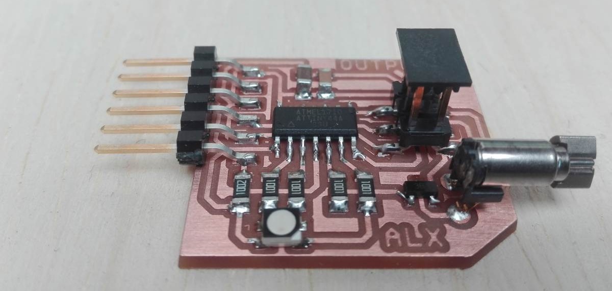
I select the microcontroller taking into account several points. The first one has 4 outputs (3 for the led and 1 for the engine) and also has the output for the FTDI. The attiny 45 has 6 pins available would be useful, but I do not want the programming pins are the same that control the devices, so use the Attiny44 this time I'm going to use it with an internal oscillator that adds 2 more pins to my card.
Another way to select is identifying the needs if I want to modify the speed of my engine and the brightness of my led, I need a PWM many microcontrollers do not have this feature then I would have to put a microcontroller that supports 4 pwm.
But there is a very useful technique that all microcontrollers have, is to create times under logic arduino can create several PWM in pins that do not have it.
Something very interesting that I could see is that Neil also applies this system, before I had tried with little success but this time I'm going to join my experience with Neil's code and try.
The interesting thing that Neil does and I like very much is not to use arduino much, rather Neil creates his own codes that simulate the arduino libraries.
Electronic design with eagle
I return to work with eagle to make my output board, now my challenge is not to place the resonator this saves space.
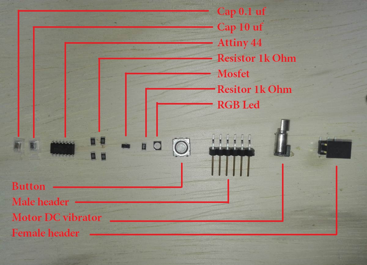
List of the components to use
- Microcontroller Attiny44
- Ftdi pin header
- Connector 1x02
- Resistors 1k Ohm
- Resistors 10k Ohm
- Capacitor 10uf
- Capacitor 0.1uf
- RGB led
- Mosfet
- Header to programmer
Vibrating motor
A DC motor converts electrical energy into mechanical energy. When the electric current flows through the motor, creating an internal force where the rotor rotates in a permanent direction, if I want to change the direction of rotation of the rotor, I have to change the direction of the current. If I want to change the direction of the motor from the controller I have to use a driver, in my case I just want to control the speed then the mosfet acts as driver for the motor.
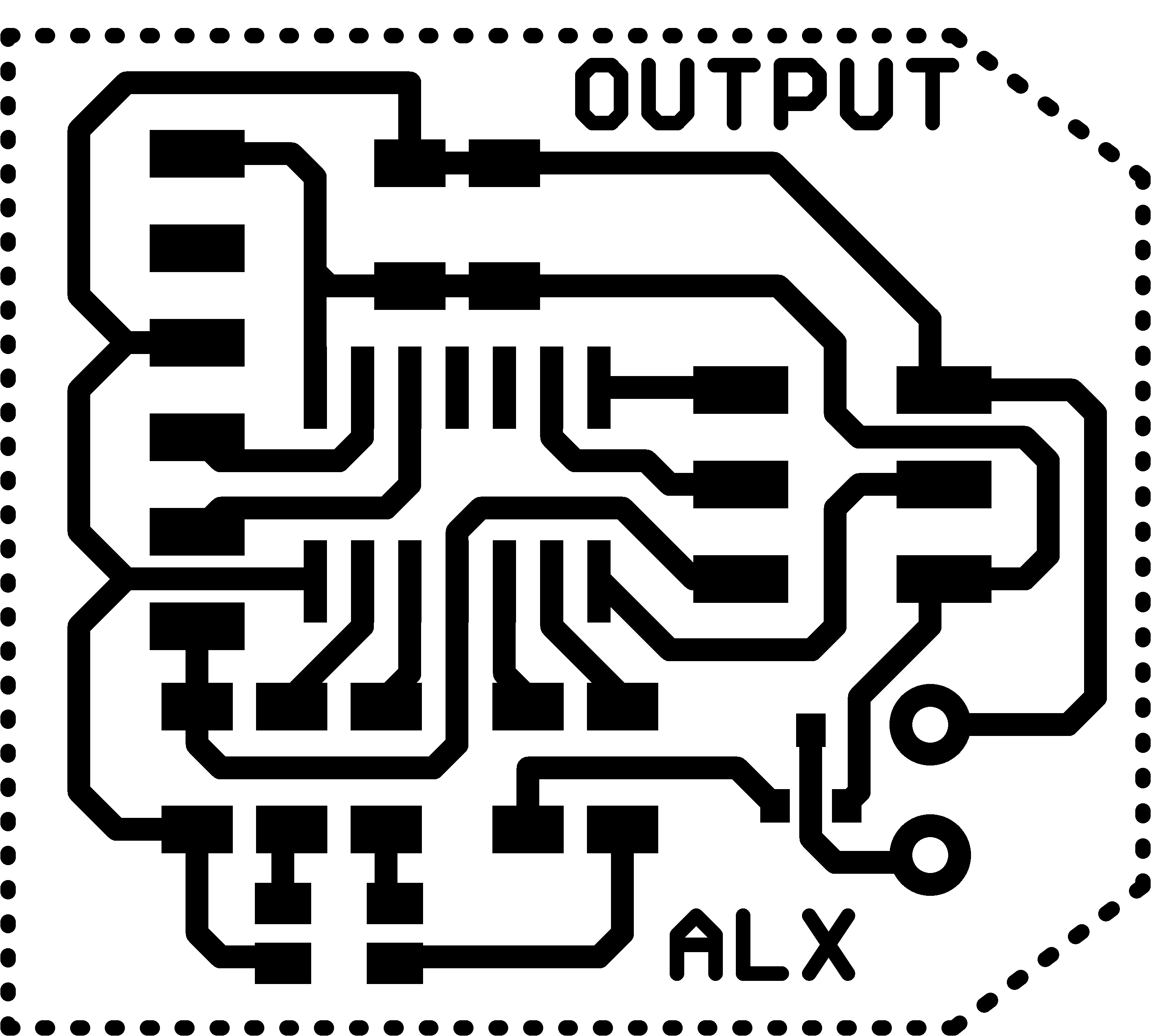
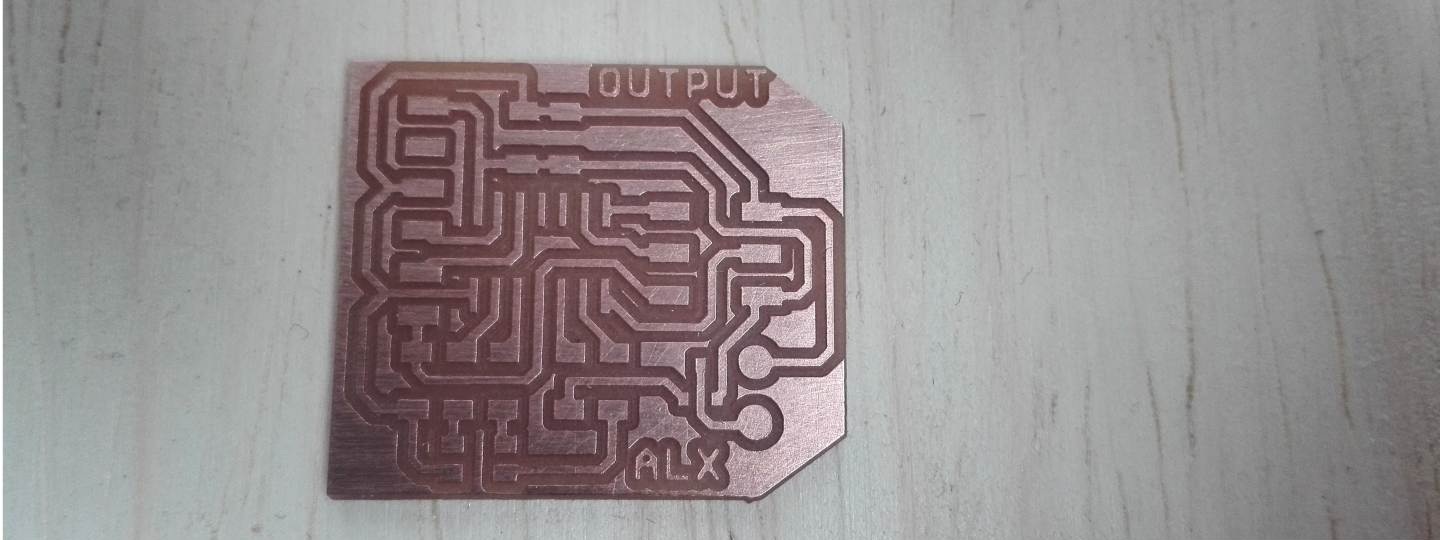
With the schematic ready now it's time to make the board
.png)
.png)
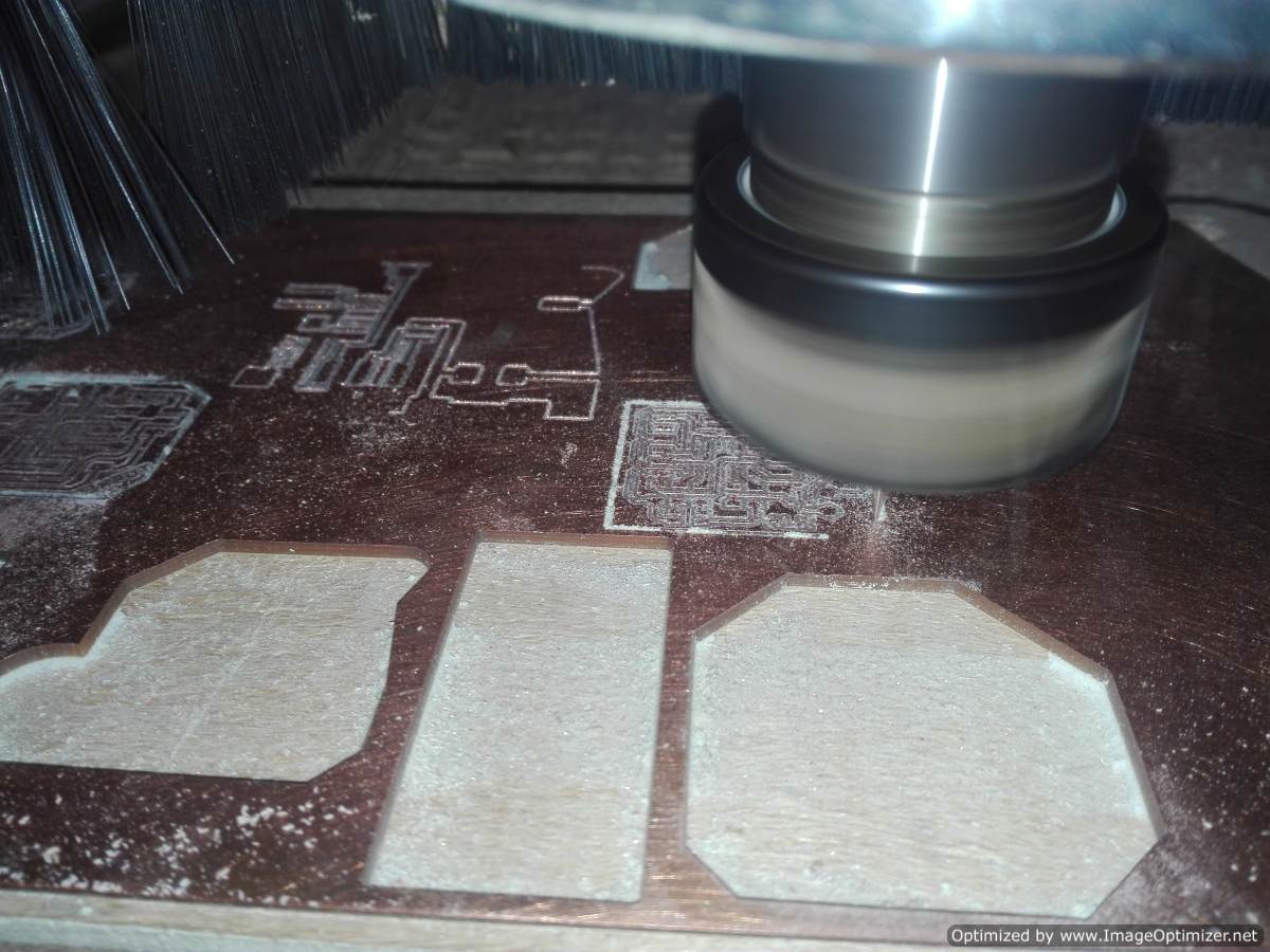
Edit Image and generate G-code
I go back to the editing of the images generated from eagle, now I put names to the PCBs for a better identification.


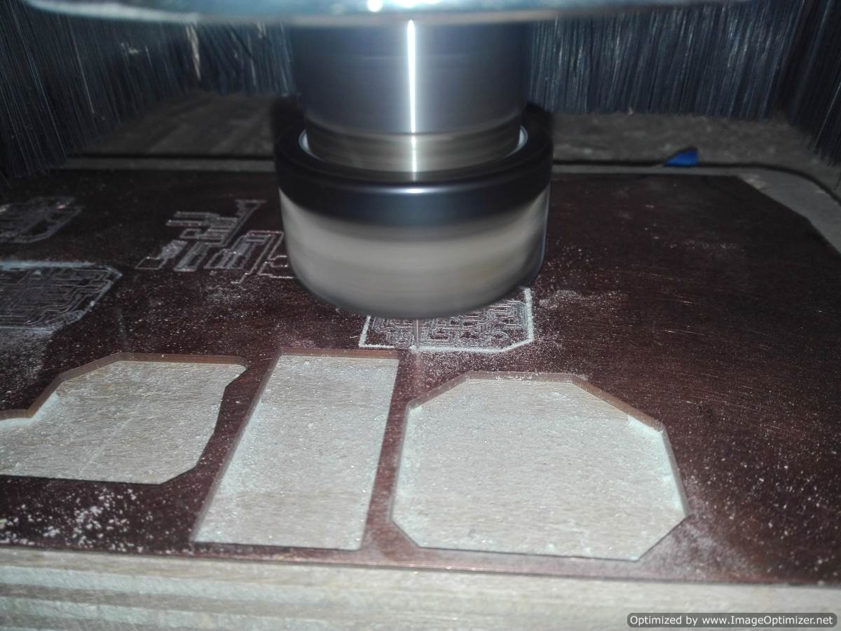
Milling and Electronic Production
With the files ready to go to the milling, after so much practice I'm improving the design of my board is much easier.
In this step have select the BOM (Bill of Materials)
Although we have named them before, it is very convenient to identify them according to their package.
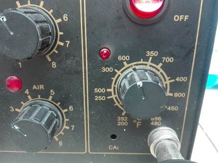
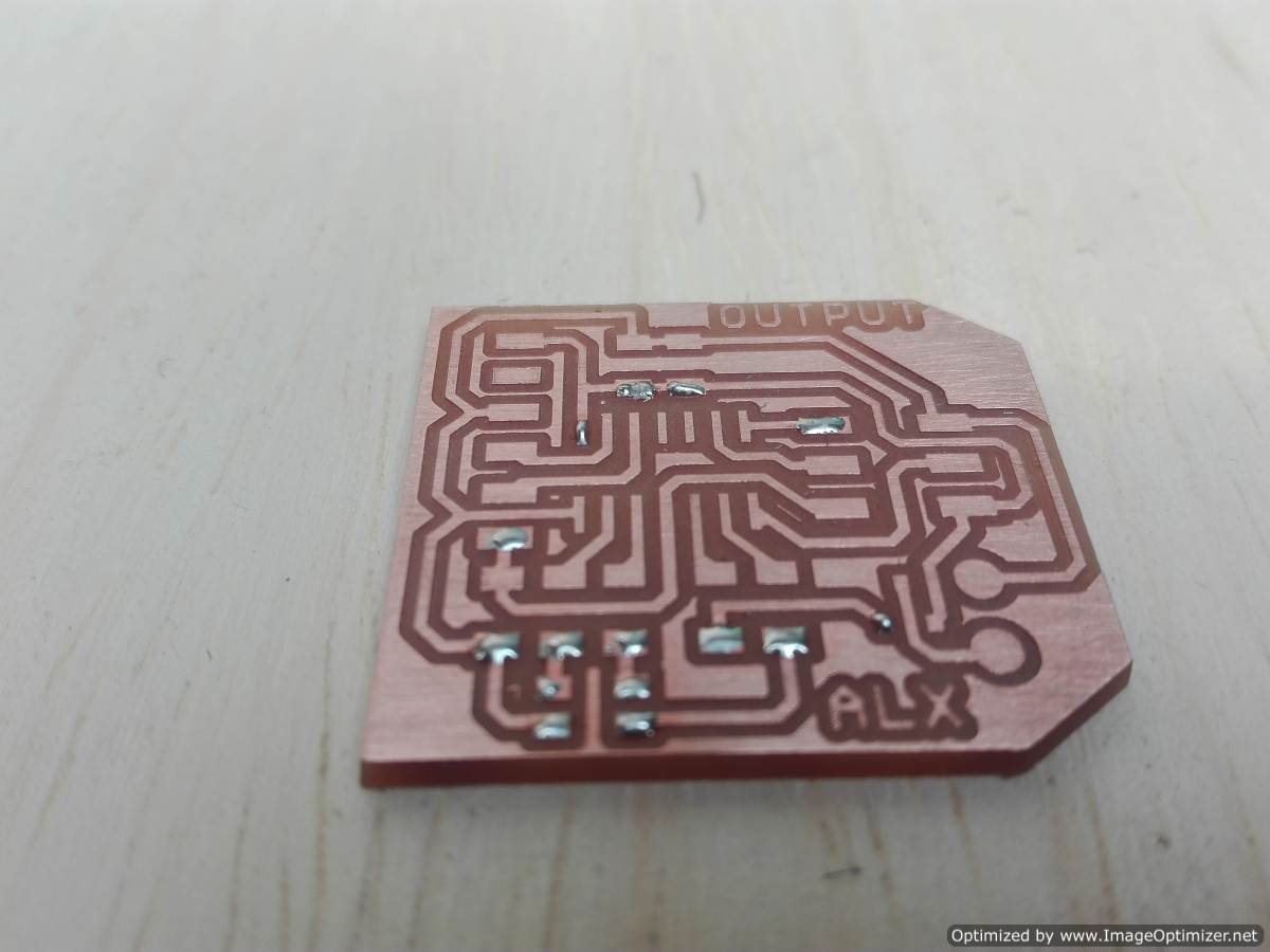
To weld the components use the captive at a temperature between 300 and 350 degrees centigrade. I have a very good technique that allows me to weld the components faster. I put a little tin on the board, a point for each component that helps me hold and then solder it.
Programming
First, as it is programmed for an engine to turn on and start, this would be ON-OFF control. Second how the speed is varied this is PWM.
Configuration with arduino:
In my case I have serial communication so I add the library, I have the custom to name each one of the pins that I am going to work with.
The void setup made the configuration in my case I have 4 output, then I set them, for the case of the engine should start off 0 in its output, for the RGB LEDs to start off we must place 1 in its output. I use the pinMode commands to configure and digitalWrite to write the output value.
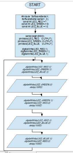
#include "SoftwareSerial.h"

SoftwareSerial serial(1, 0); //PIN 12 AND PIN 13 ATTINY44  (RX,TX)
const int LED_RED = 7;
const int LED_GREEN = 9;
const int LED_BLUE = 10;

void setup()
{
  serial.begin(9600);
  pinMode(LED_RED,   OUTPUT);
  pinMode(LED_GREEN, OUTPUT);
  pinMode(LED_BLUE,   OUTPUT);
  pinMode(MOTOR, OUTPUT);

  digitalWrite(LED_RED,1);
  digitalWrite(LED_GREEN,1);
  digitalWrite(LED_BLUE,1);
  digitalWrite(MOTOR,0);
}
Now all the code goes in the loop, just like before I want the led rgb and the engine to turn off, I'm going to turn on the green, red and blue led each one with a space of 1 second. After this the engine is started.
void loop()
{
  digitalWrite(LED_RED,1);
  digitalWrite(LED_GREEN,1);
  digitalWrite(LED_BLUE,1);
  digitalWrite(MOTOR,0);

  digitalWrite(LED_GREEN,0);
  delay(1000);

  digitalWrite(LED_GREEN,1);
  digitalWrite(LED_RED,0);
  delay(1000);

  digitalWrite(LED_RED,1);
  digitalWrite(LED_BLUE,0);
  delay(1000);

  digitalWrite(LED_BLUE,1);
  digitalWrite(LED_RED,0);
  delay(1000);

  digitalWrite(MOTOR,1);
  delay(1000);
}
This would be on-off control now as I am going to configure the code to be able to vary the speed. In this case we need PWM and know how it works, for the PWM output the AnalogWrite command is used.
I found a good reference on the arduino page about PWM
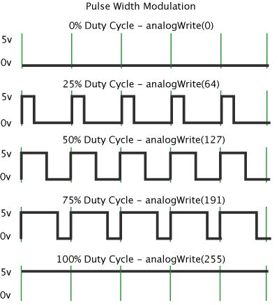
Pulse Width Modulation, or PWM, is a technique for getting analog results with digital means. Digital control is used to create a square wave, a signal switched between on and off. This on-off pattern can simulate voltages in between full on (5 Volts) and off (0 Volts) by changing the portion of the time the signal spends on versus the time that the signal spends off. The duration of "on time" is called the pulse width. To get varying analog values, you change, or modulate, that pulse width. If you repeat this on-off pattern fast enough with an LED for example, the result is as if the signal is a steady voltage between 0 and 5v controlling the brightness of the LED.
In the graphic below, the green lines represent a regular time period. This duration or period is the inverse of the PWM frequency. In other words, with Arduino's PWM frequency at about 500Hz, the green lines would measure 2 milliseconds each. A call to analogWrite () is on a scale of 0 - 255, such that analogWrite(255) requests a 100% duty cycle (always on), and analogWrite(127) is a 50% duty cycle (on half the time) for example.
Once you get this example running, grab your arduino and shake it back and forth. What you are doing here is essentially mapping time across the space. To our eyes, the movement blurs each LED blink into a line. As the LED fades in and out, those little lines will grow and shrink in length. Now you are seeing the pulse width.
Written by Timothy Hirzel
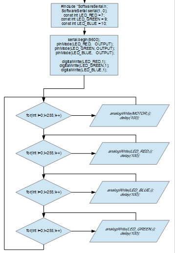
Now the new code would be the following:
void loop()
{
  for(int i=0;i<255;i++)
  {
    analogWrite(MOTOR,i);
    delay(100);
  }

  for(int i=0;i<255;i++)
  {
    analogWrite(LED_RED,i);
    delay(100);
  }

  for(int i=0;i<255;i++)
  {
    analogWrite(LED_BLUE,i);
    delay(100);
  }

  for(int i=0;i<255;i++)
  {
    analogWrite(LED_GREEN,i);
    delay(100);
  }
}
I can only play with the values of the colors to combine them, remember that 255 is off and 0 is on.
Test
Group assignment
Measure the power consumption of an output device
How is the power measured? What is the power?
The power of a system is the work done in the unit of time. Its unit in the International System (SI) is the watt, defined as the power of a machine that performs the work of a July in the time of a second. Its symbol is W.
To measure the power we need 3 steps and the multimeter
Record the circuit voltage. With the multimeter we take the value of the voltage generated in the circuit or parallel to the device to be measured.
Record the circuit current. We change the connections in the multimeter to measure current, remember that measuring the current is different from measuring voltage, the current is measured in series to the device to be measured.
Define the electric power. With the data already registered now we can calculate it with a simple formula, if the measurements were correct the value will be the closest or the correct.
Power = current * voltage
P = I * V
The power supply voltage of my card is 5v, while when measuring the current the multimeter registers the value of 250m.
After the calculation the consumption of my card is:
P = 5V * 0.25 a
P = 1.25 W
To this practice I include a oscilloscope to identify the state of the pin
