COMPUTER-CONTROLLER CUTTING
In this class we have to work as a team and discover our laser, each of the team members knows something different so this experience will be very good. We also have an individual assignment where they ask us to perform a presfitkit. I do not know what it is but I'm going to uncover it, they ask us to use the parametric design for presfit and they also ask us to do something in the vinyl cutter. Important data never used lasser so this is something new for me.
Group assignment
Characterize your lasercutter, making test part(s) that vary cutting settings and dimensions
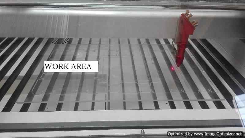
The laser cutter is very robust for cutting jobs in your work area.
It consists of different devices starting from the front with your work table, where you have rulers to support the work material.
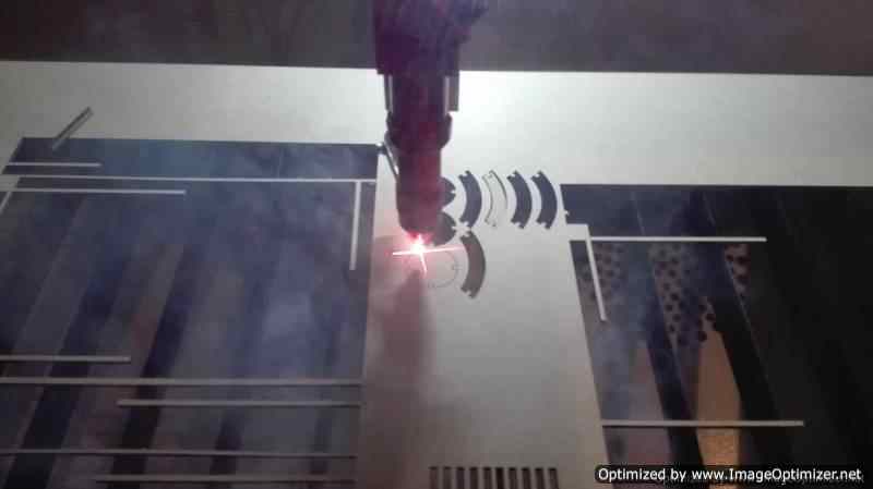
It has a transparent cover that allows to visualize the process, here is also the laser who does the work.
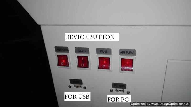
It has illuminated green metal colored power buttons, a red button for emergency stop and a light that allows to control the current.
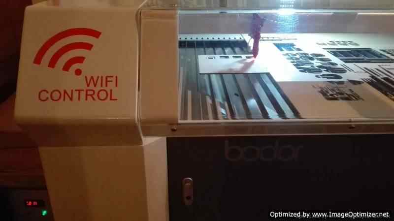
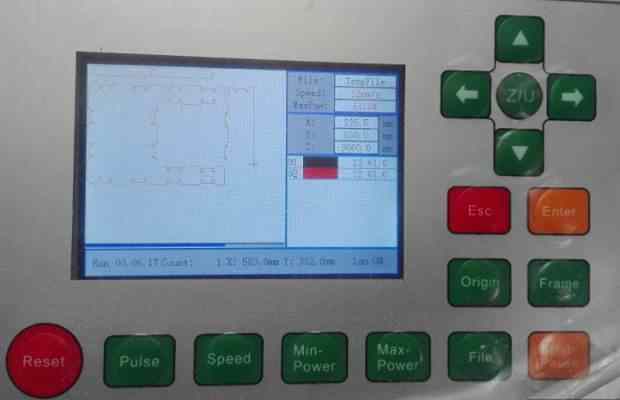
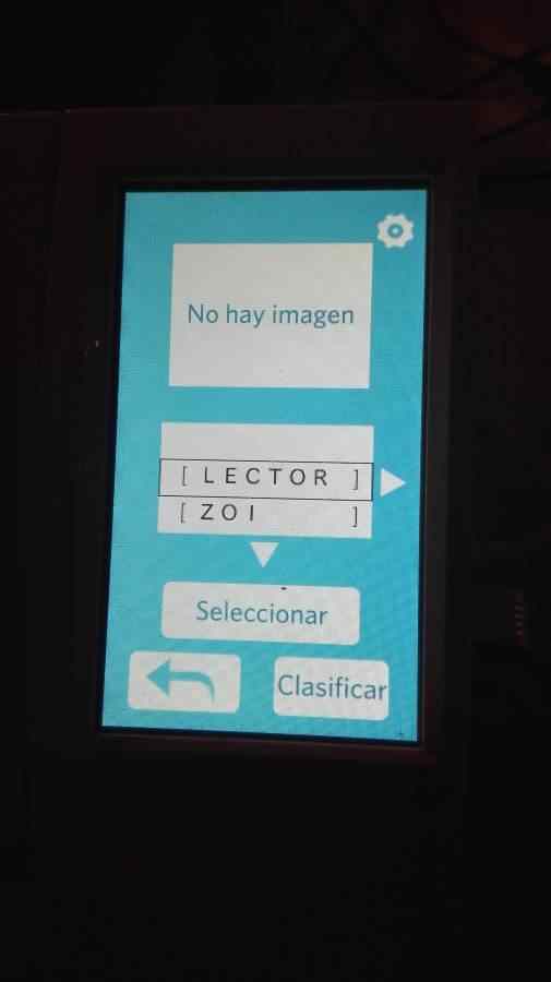
The machine has a screen that allows browsing to find the file when a USB is placed, it also allows to visualize the process that is being carried out.
It is good to mention that the machine allows its connection via USB cable and wifi.
The laser machine needs different equipment for its correct operation.
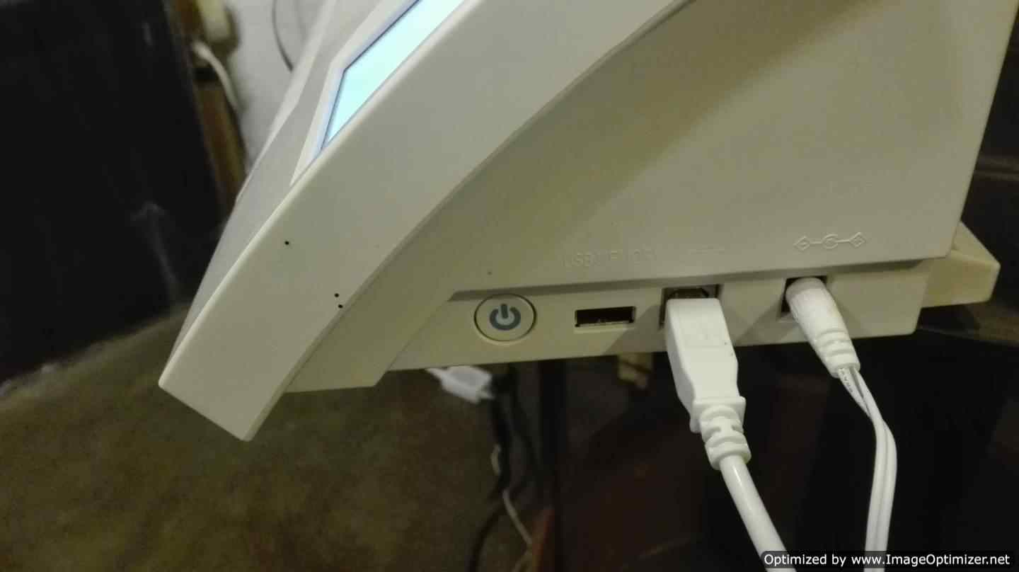
The machine on its right side has buttons that allow you to turn on your equipment, here are also the inputs for the usb device and for the connection with the computer
 |
 |
 |
 |
 |
 |
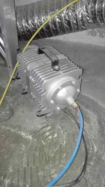
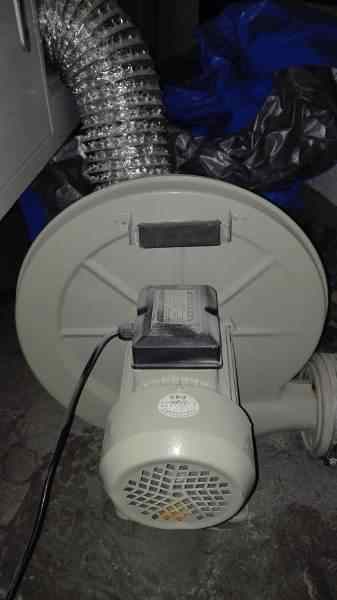
The laser machine needs different equipment for its correct operation.
The air extractor serves to remove the gases that are produced during the cutting or engraving process. Treat gases to go outside to avoid health problems when inhaled
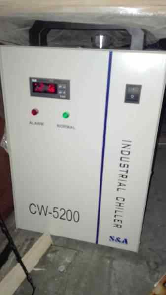
The chiller serves to cool the tube that is used to generate the laser. The chiller should not exceed 28 degrees centigrade, the machine will give a warning of overheating
| Air pump | Air Extractor | Chiller |
|---|---|---|
 |
 |
 |
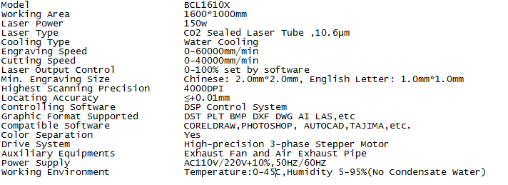
Technical Parameters
In the network I found the technical characteristics of the machine I mention acontinuation, you can also visit the following link
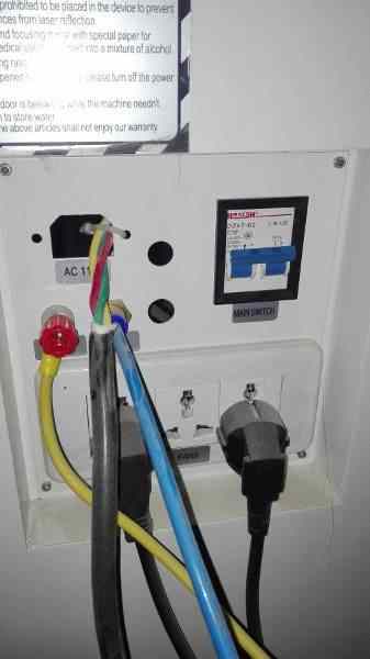
Process to turn on maquine
- Connect the laser machine (110v AC)
- Connect the chiller (110v AC)
- Check in the back if the equipment is connected
- Turn on the blue breaker that is on the back of the laser machine, you will hear how the estractor and the air pump turn on
- Turn the red button to the right to activate it.
- Press the metallic button to turn on the machine, the green light will activate.
- Wait for the laser to position
Process to make a cut
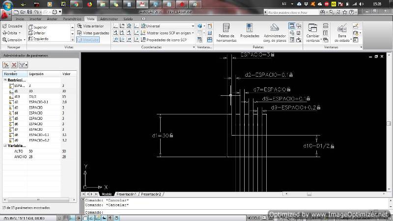
- I create a small design in autocad, the cut is done in 3 mm acrylic.
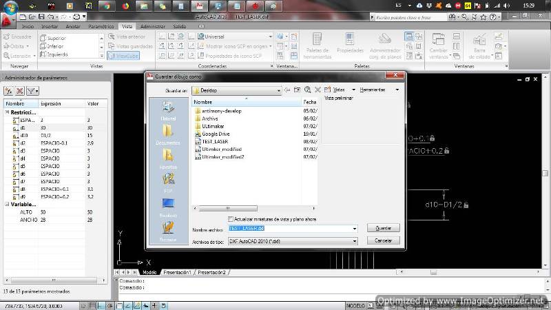
- The RDwork v8 software is used to send the cut file install it.
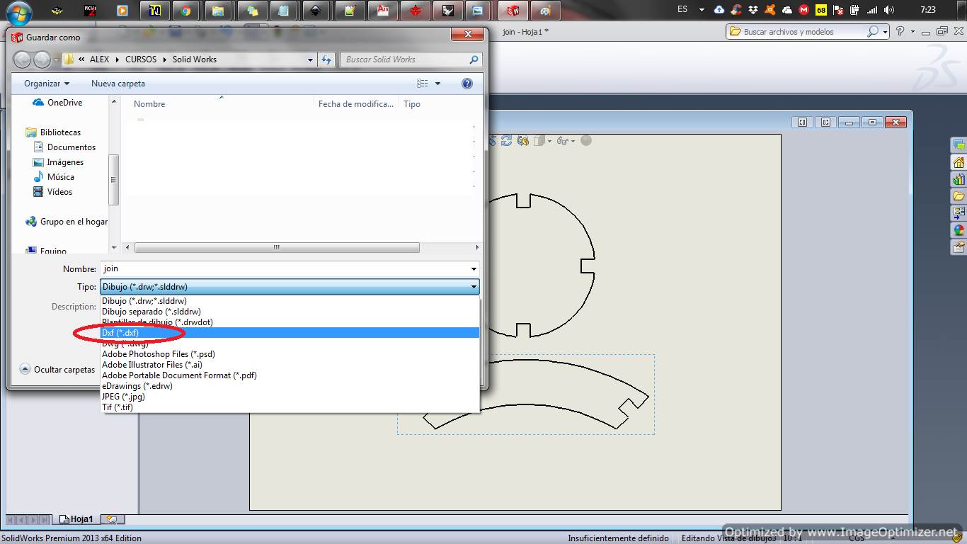
- You have to save the file in .dxf format for the software to read it.
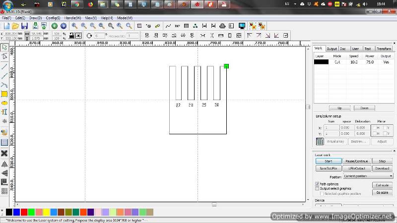
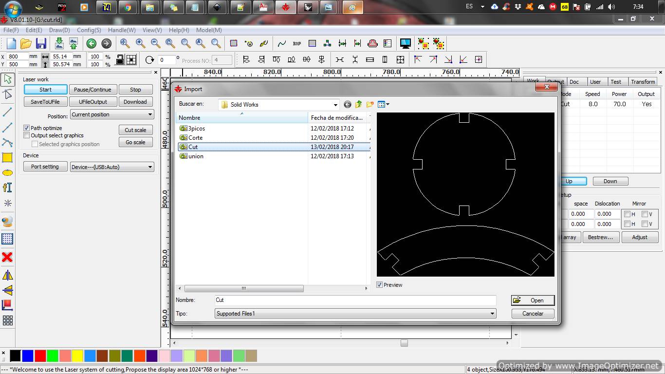
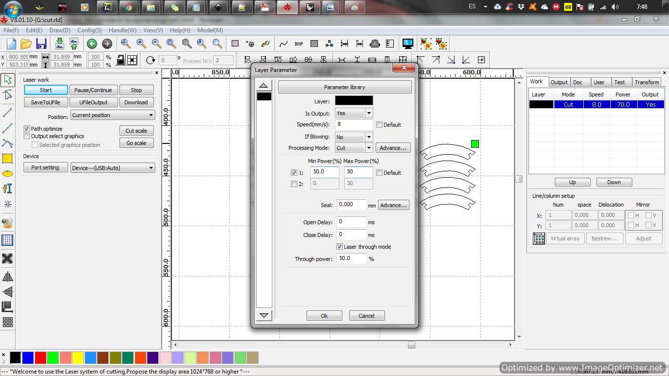
- When we are in the RDwork v8 we import the file.
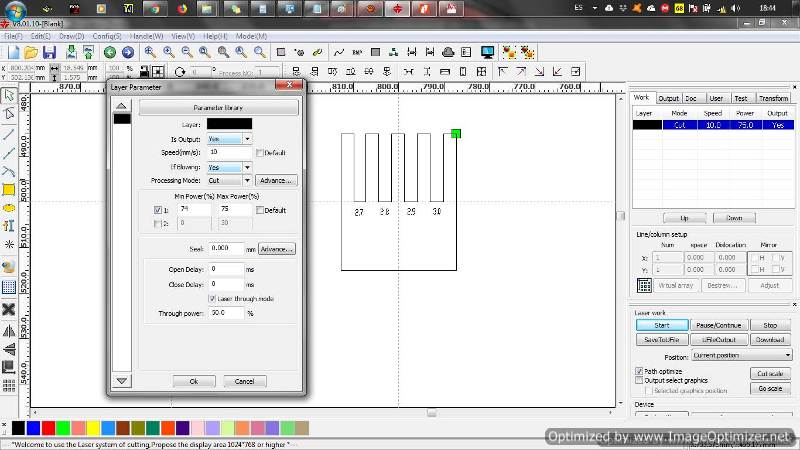
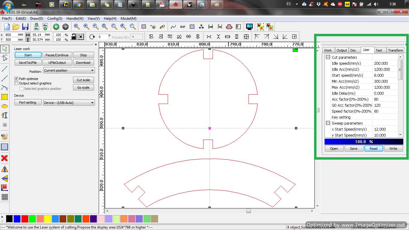
- We make the configuration of the parameters of power and speed. For more information about the installation, check the following file
Laser WORKS 8 Install
 |
 |
 |
 |
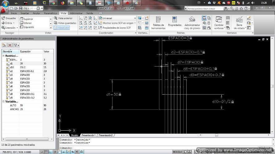
Demonstrate and describe parametric 2D modelling process
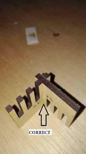
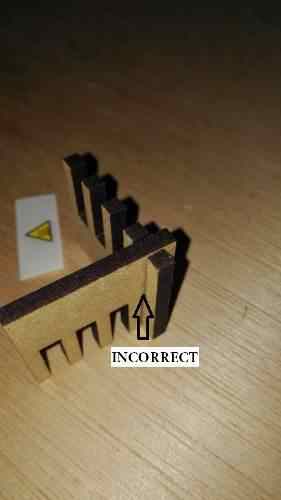
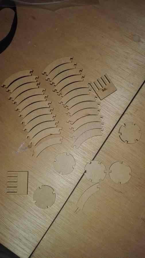
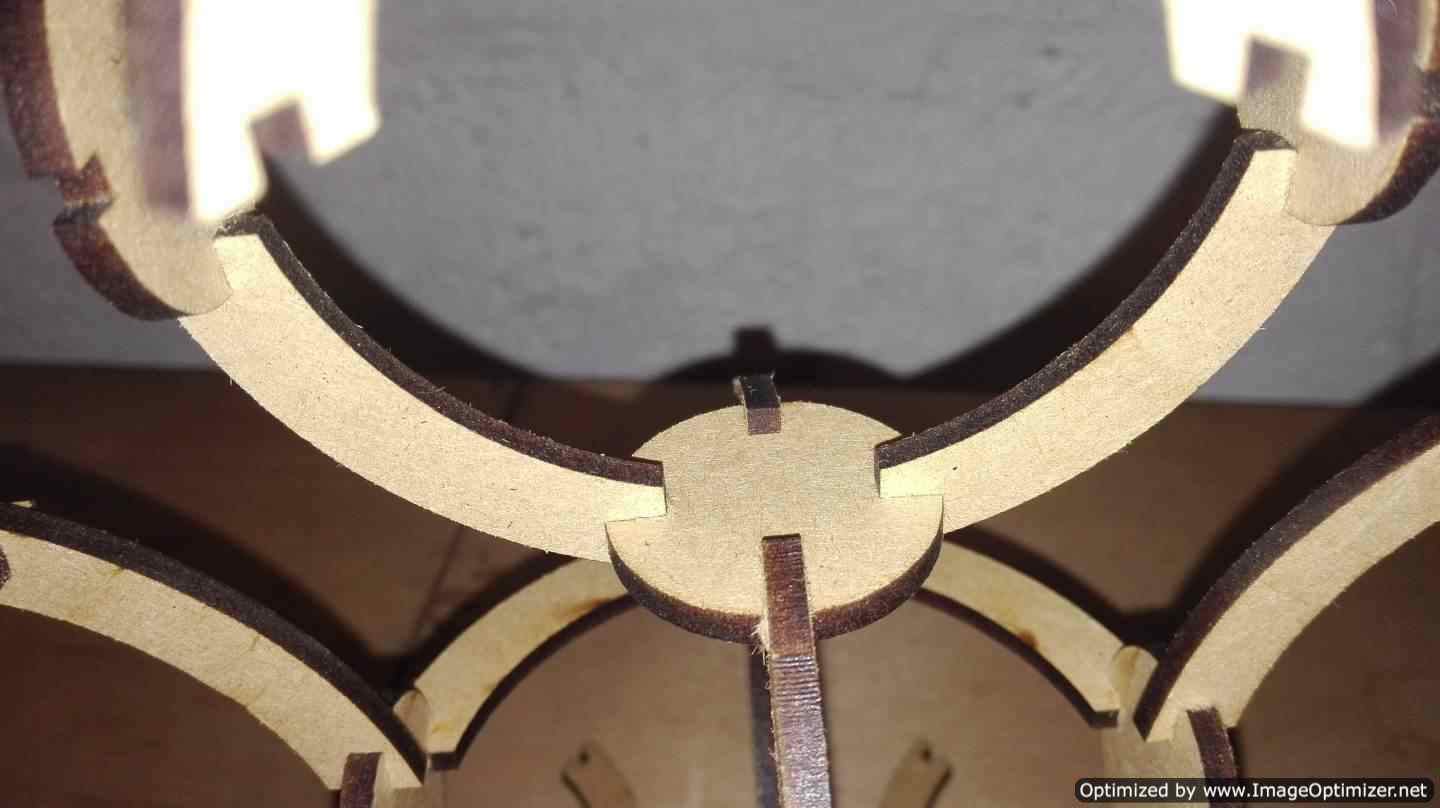
Determine the base size of a notch under pressure: I create a design to find the notch and correct pressure in the material. Create a parametric design in autocad in the form of a consecutive u. I identify the thickness of the material, in my case it is 3mm. I cut the material with several notches, example 2.8, 2.9, 3.0, 3.1, 3.2 and made adjustment tests Cut 2 pieces and I saw that the best fit is made with the notches of 3.1 mm
 |
 |
 |
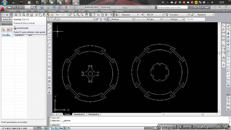
To create the parametric design of my pressfit kit start with a drawing I did in autocad with circles and lines. I wanted to parameterize in autocad but I realized that it is very complex so I chose to go to solidwork. With my drawing already made it was easier. Once the notch is identified, leave the parametric variables ready to be modified.
Why did I change from Autocad to SolidWork?
The parameterization in autocad is complicated when creating more complex pieces besides I wanted to try a different software and this was the option.
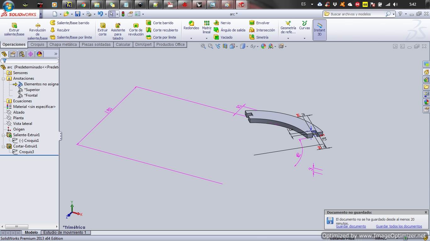
I use solidwork to make the pieces for my press fit kit.
To realize my basic design created in Autocad.
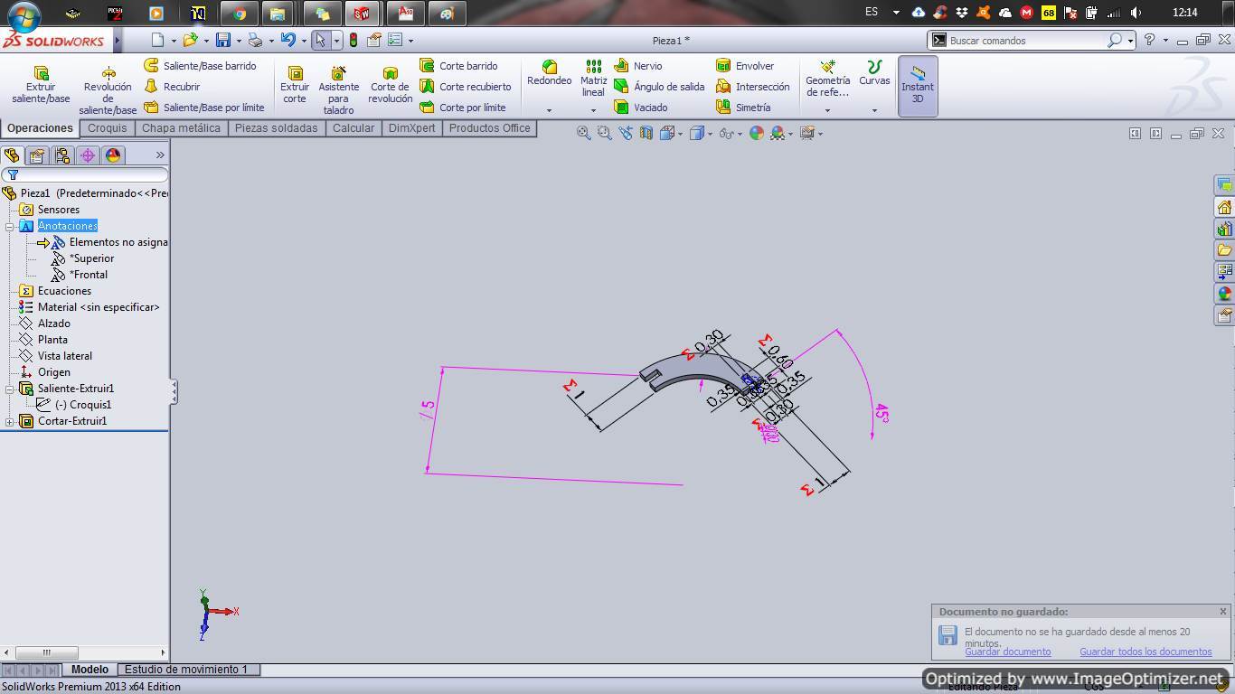
How to parameterize in Solidwork?
After relizing the scketch, the intelligent dimension tool is used to perform the measurement restrictions, a name can be assigned to the dimension.
An example if we have the dimension1=D1@Sketch1 and we want the new dimension to be half, then it will be dimension2="D1@Sketch1"/2
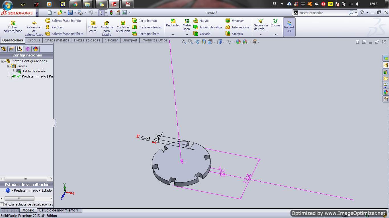
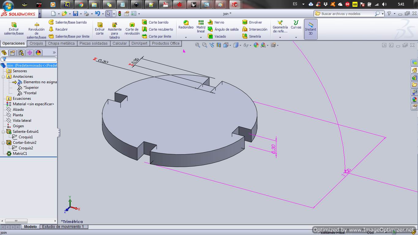
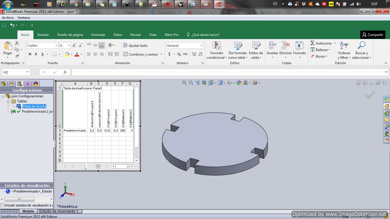
In solidwork I create the 2 pieces.
With piece 1 start with a basic figure of a circle then extrude it according to the size of the material and make the necessary cuts in each of the corners.
Take into account all values are parameterized.

Create the file from solidwork for the laser cutter
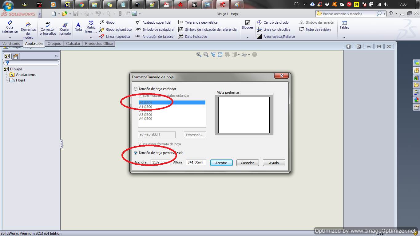
After creating the pieces you have to create a new drawing in Solid Works to create the cut files.
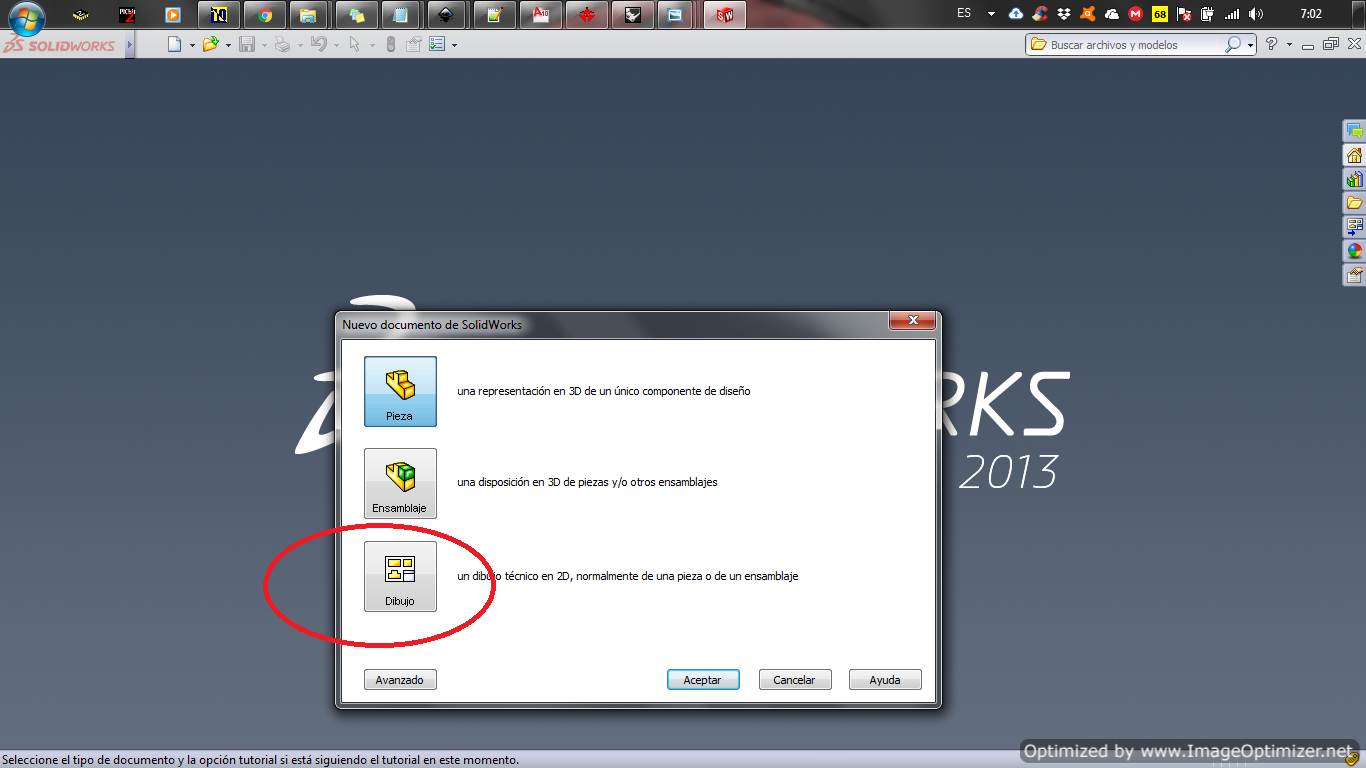
We select an appropriate format for our drawing, personally use custom size
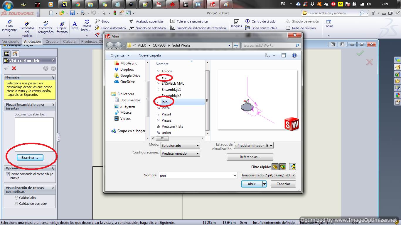
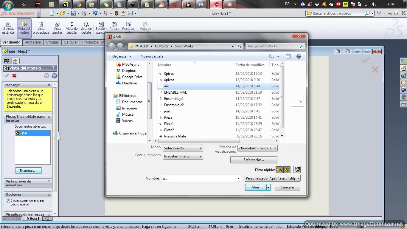
Click on browse and select each of the pieces
After selecting the piece, choose the view to show on the screen in this case the top view.
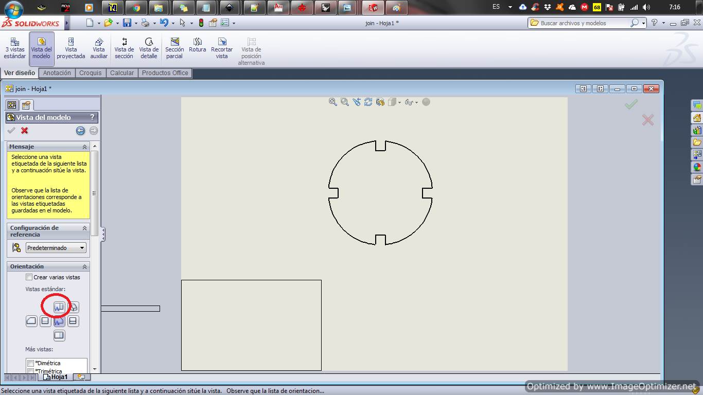
We save the file in the proper format and the file is ready
Identify and explain processes involved in using the laser cutter
With the file ready in .dxf format we go to RDwork and start with importing the file
Connect the laser by usb cable in the user tab press read, wait until the connect
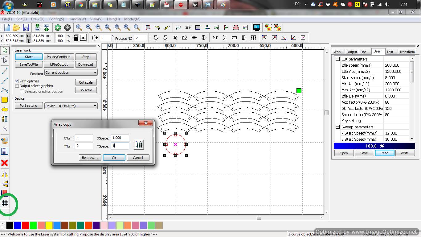
A piece is chosen and with the matrix tool the iron is made for cutting
Finally configure the power and cutting speed, it is important to mention that we have to configure the height of the laser to mdf
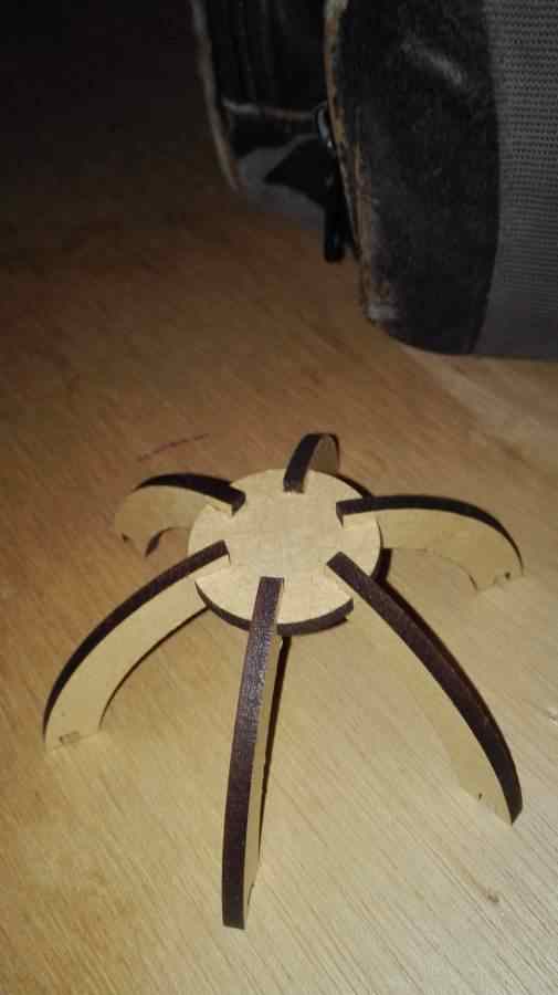
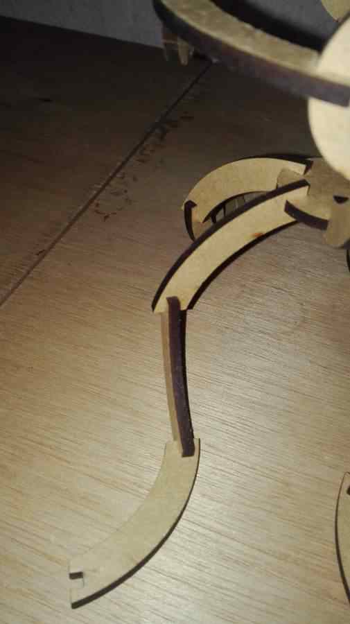
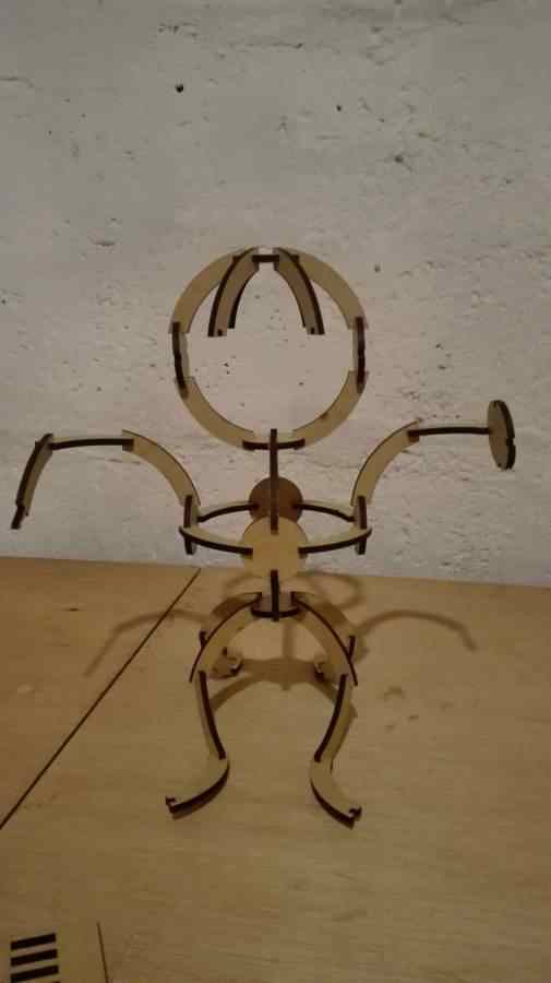
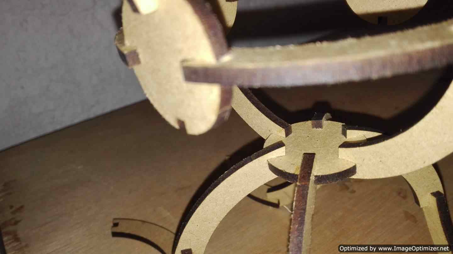
with the pieces ready at the end I have thousands of ways to put together, the notch as the design at the beginning of 3.1mm did not have any problem but it would be very good to try more figures
There are various laser tubes with different powers to choose from such as 30W laser tube, 80W laser tube, 150W laser tube (big power laser tube), etc. In my case the tube of the laser cutter is the 150W.
If you need more information of the laser cutter read the next archive.
Vinyl Cutting
Identify and explain processes involved in using this machine.
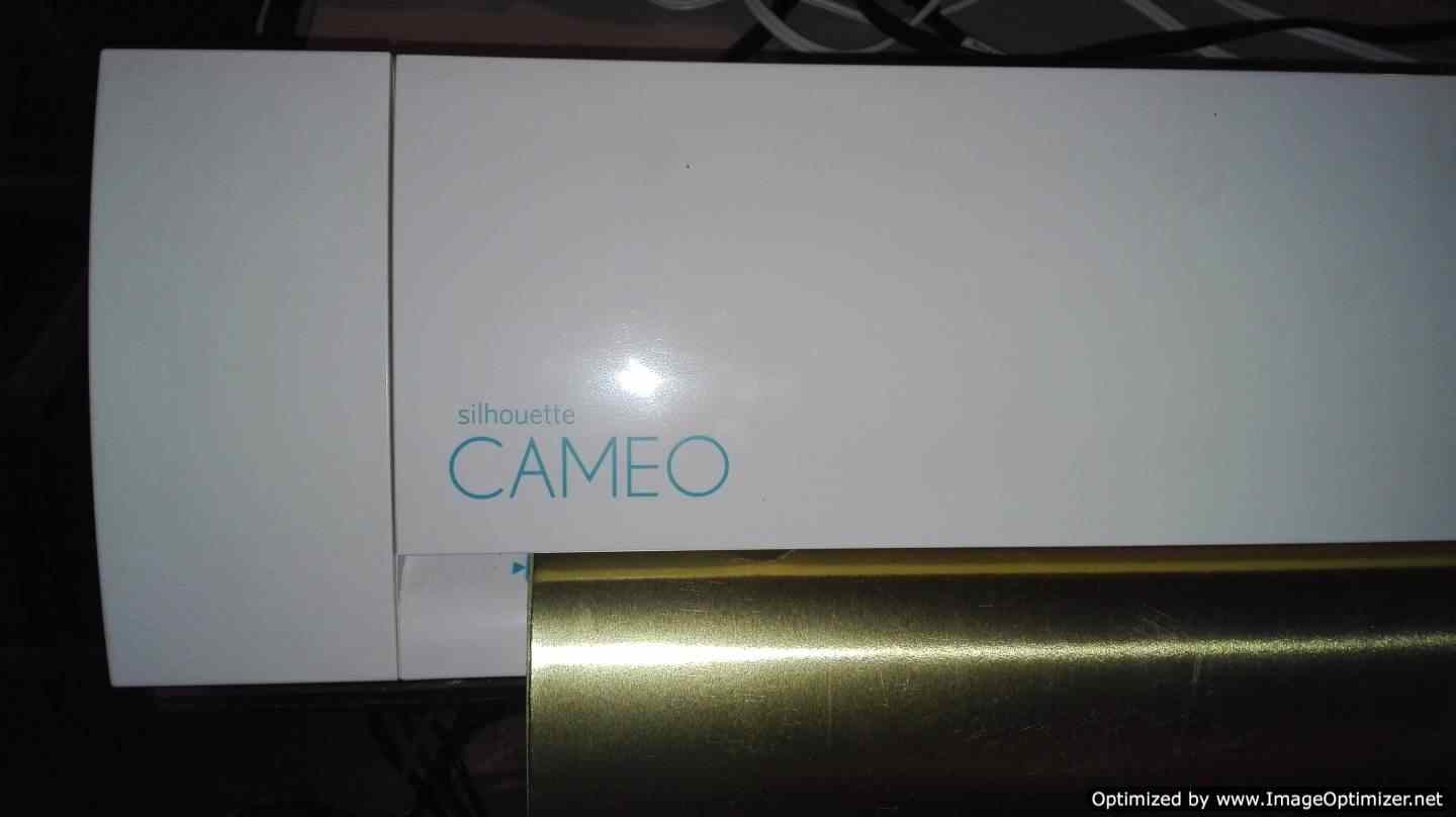
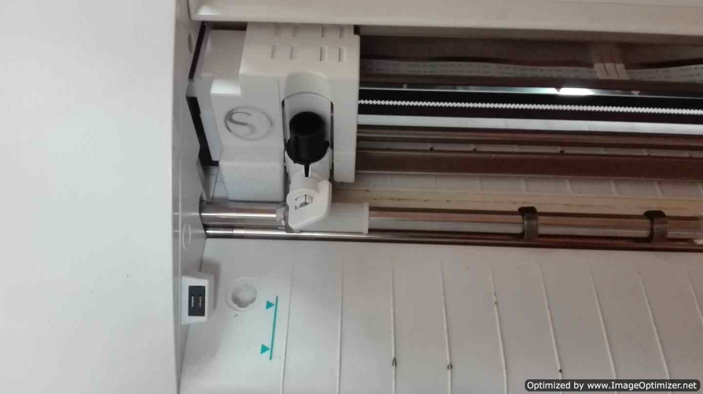
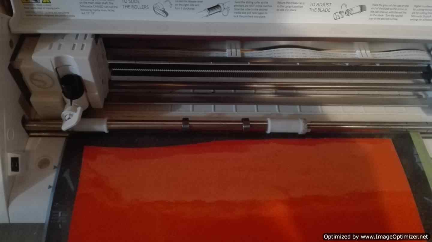
For this vinyl cutting activity. I used the CAMEO machine that has a dimension of 35 cm. This machine has a blade that can change its height depending on the material.
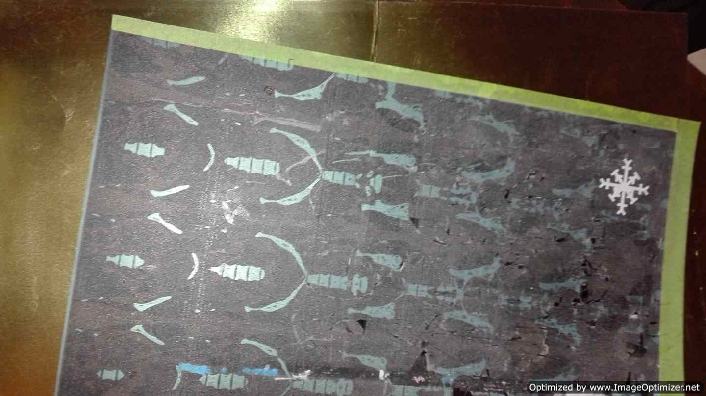
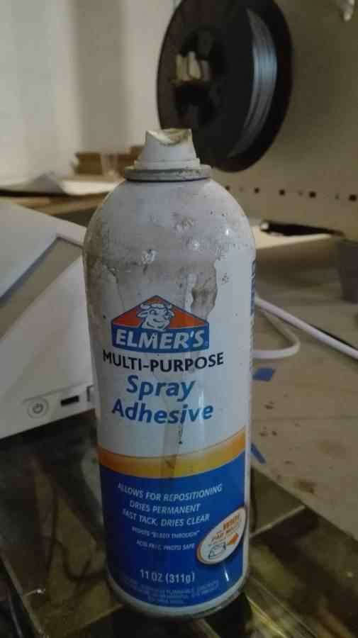
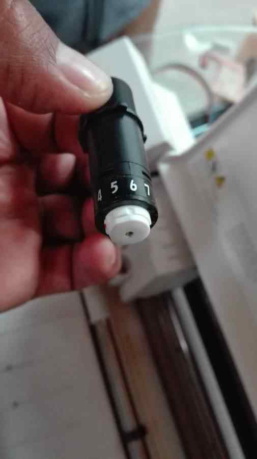
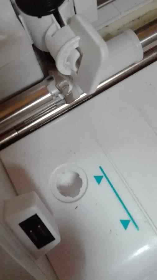
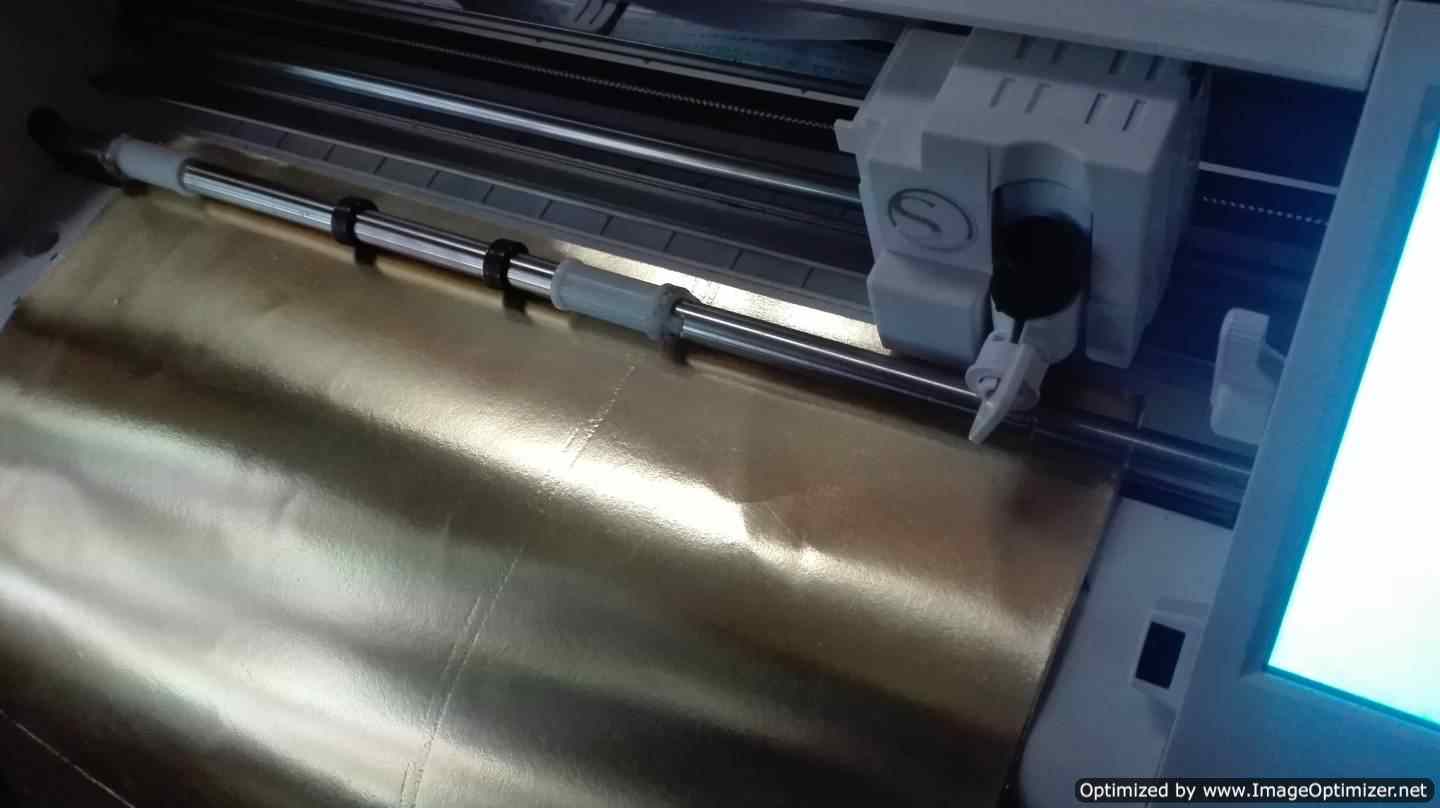
I configure the material to use, in my case I use a golden material of 1 mm thick, I use a spay adhesive and a sacrificial material so as not to damage the machine, the blade is removed from its cutting place to change its height. In the same machine you will find a hole where you can change the working height this machine has 10 levels of cut, a little pressure is made and turn to the right, you can see how the number changes and the reference point is most recommended for The material we use is 3. This machine has USB connection to the computer on its side plus a 110V AC power cable
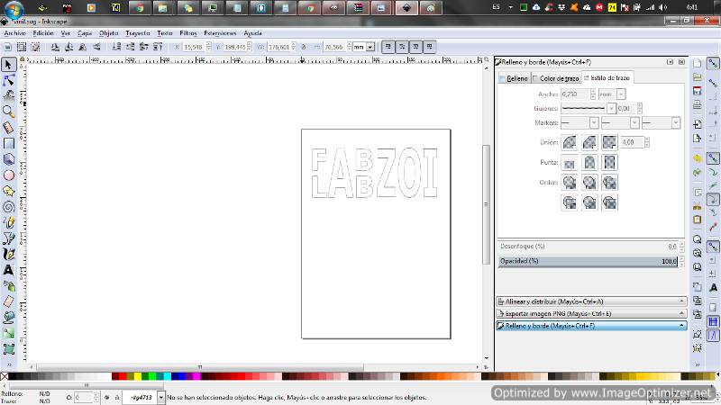
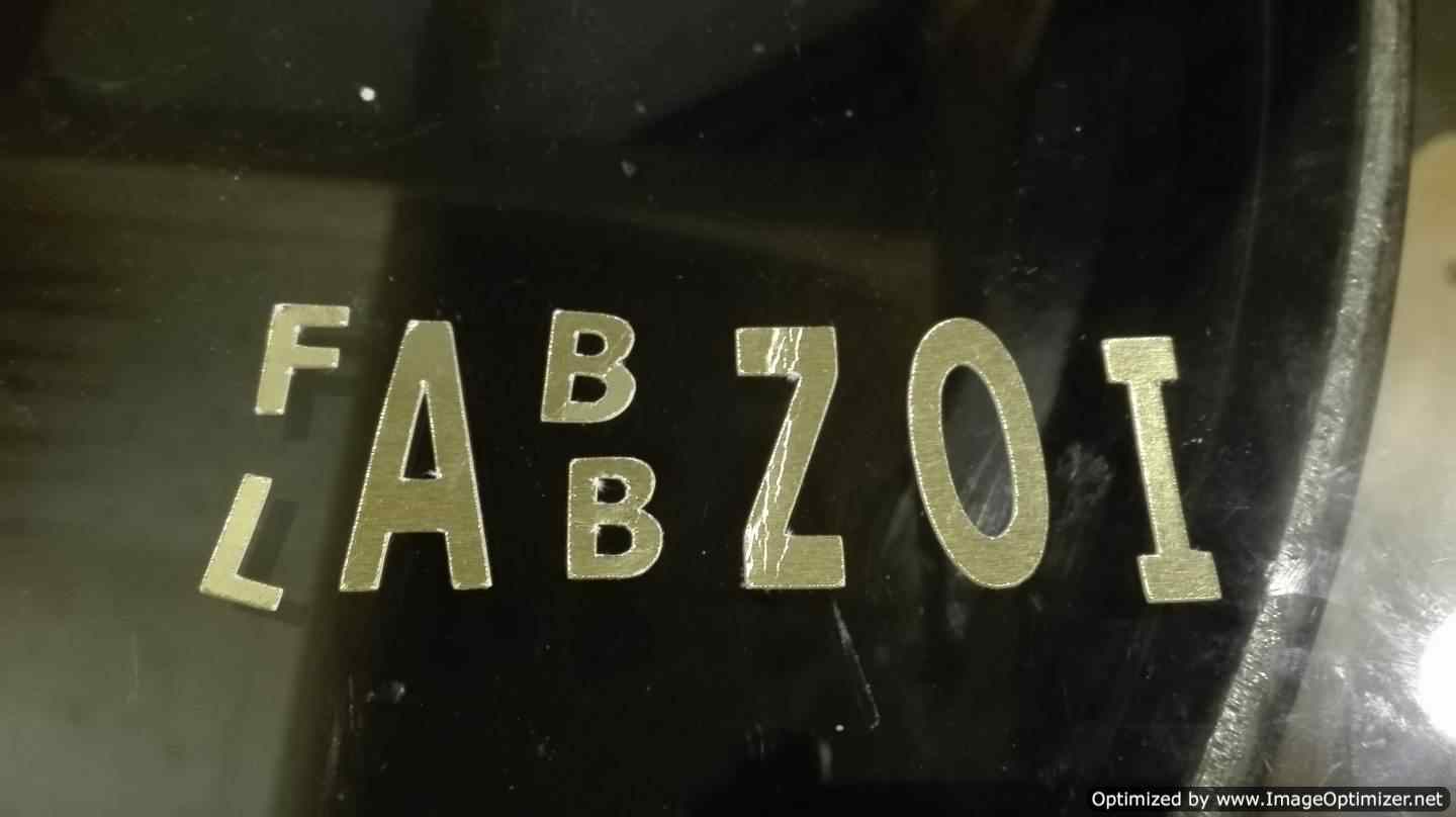
Make a drawing or a logo in a design software. Specifically, generate a vector with a thickness in the line of 0.25 mm without filling. I discovered this after making a mistake and making the letters filled. I in my case use inkscape to design a logo for my lab. I installed the software for the machine but when I try to execute it it can be opened, so I asked my partner for help and send the cut from his computer
.png)
.png)
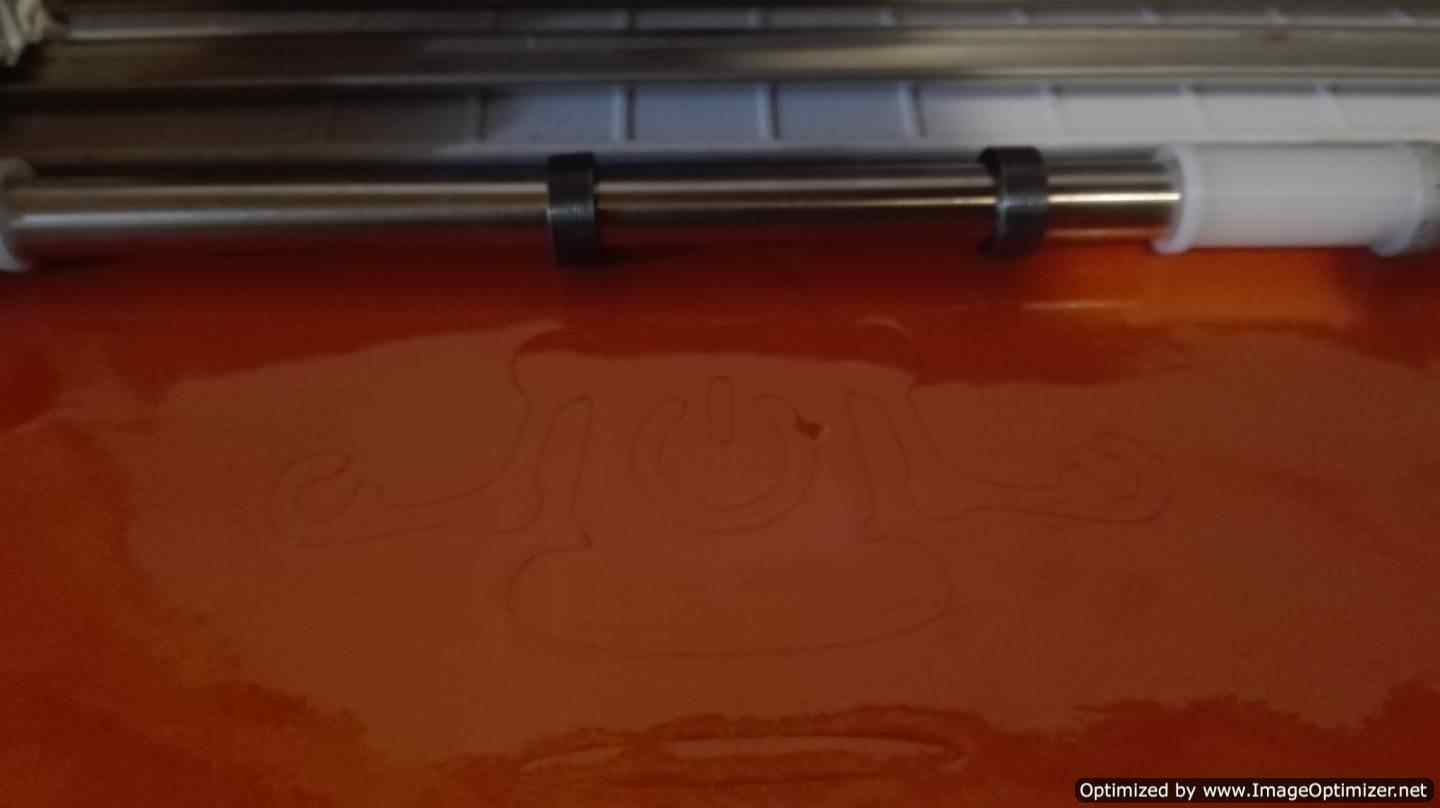
We change the measurements from inches to millimeters is a custom. I make the different configurations and finally send to make the cut.
.png)
.png)
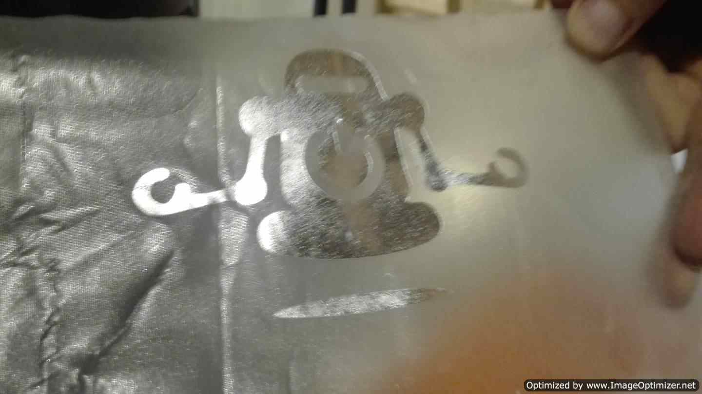
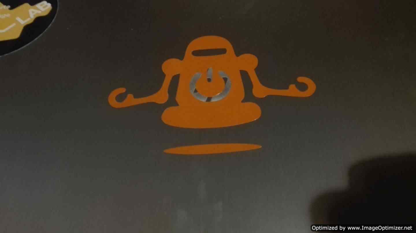
And this is the second test, I'm going to make a sticker for my computer
- The first thing is to look for an image and edit it in inkscape
- With the image already edited, we save it in dxf format.
- We choose the vinyl that we like the most, we repeat the process of adhering the vinyl to a sacrificial surface and place it in the machine.
- With the material ready, in the Silhouette Studio program we open the file and carry out the configuration of the size to be cut. And the finally send to cut.
- After the cut, you place on the vinyl an adhesive where the sticker is pasted, we try that it is very well stuck and that all the pieces of the sticker. In the end we place it in the place that we like most in my case on my computer.
.png)
.png)
.png)
.png)
.png)
.png)
.png)
.png)
.png)
.png)
CONCLUSION
I have several conclusions first that with the parametric design you can easily scale a figure, it is very ideal to create furniture with different thickness type.
The parametric design is very useful to change values or dimensions in an instant and that the rest of the figure is not altered.
The laser is good to create figures and prints with different style, I liked that you can flex materials, when they have cuts or patterns, these patterns can be parametric.
With the vinyl cutter although it sounds very simple it has its trick but it is very good to create adhesive stickers, its cut is great. The same operating logic that the laser uses is also used by the vinyl cutter, I see that many machines are similar
DOWNLOAD FILES
All the files are here