ELECTRONICS PRODUCTION
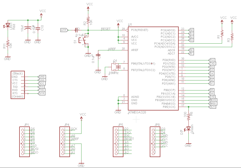
In this week we have group and individual assignment, we will learn how to make a PCB board in a machine, I always made them by hand. Neil asked us to make a test board, I'm going to try to get it right, he also asked us to choose a design of a PCB board that I believe one of the previous students, there is a lot but I'm going to do my own design. I will call it ALX ICSP and also I want to create a team that works similar to the arduino but under my design I call it FABALX
Group assignment
* Characterize the specifications of your PCB production process
Specifications of the machine
In our laboratory we use the 1325 CNC router machine while a smaller machine is activated. This machine is one of the best, it is a very precise machine, although the size is special for any PCB board
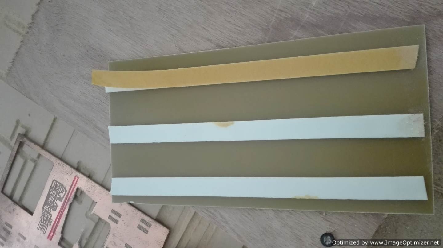
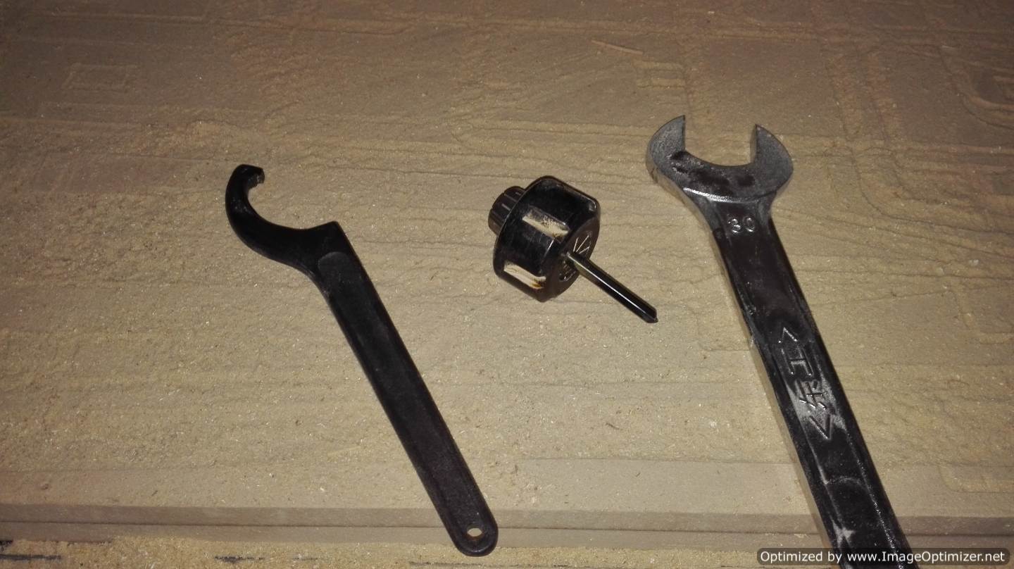
In my country there are 2 types of board 1 normal and another fiberglass. To place the copper board on the platform of the machine we use a double-sided tape. During our first practice, we learned how to change the cutting tool and the location at the zero point of work.
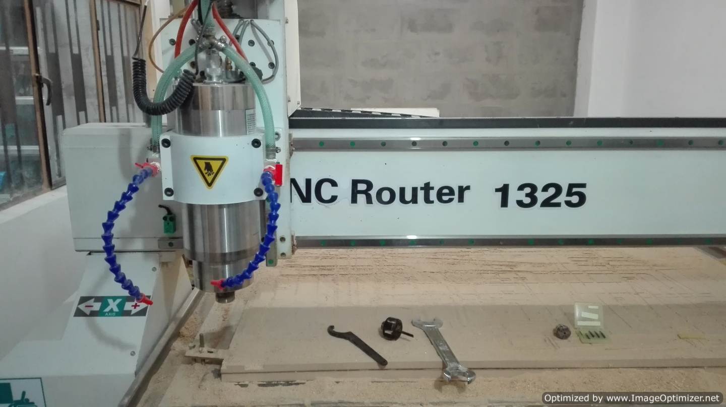
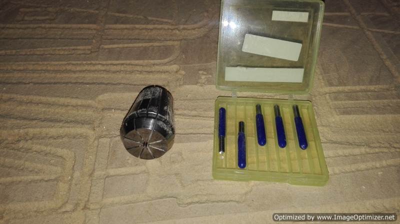
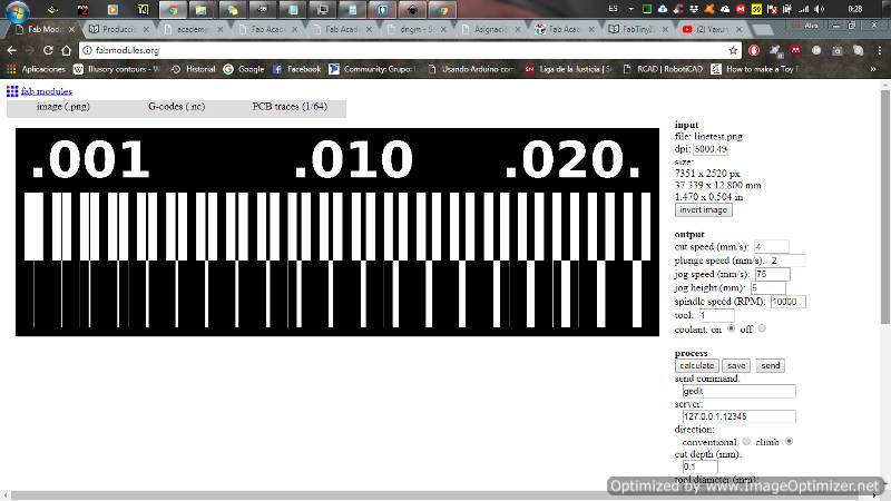
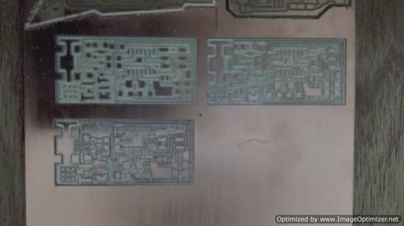
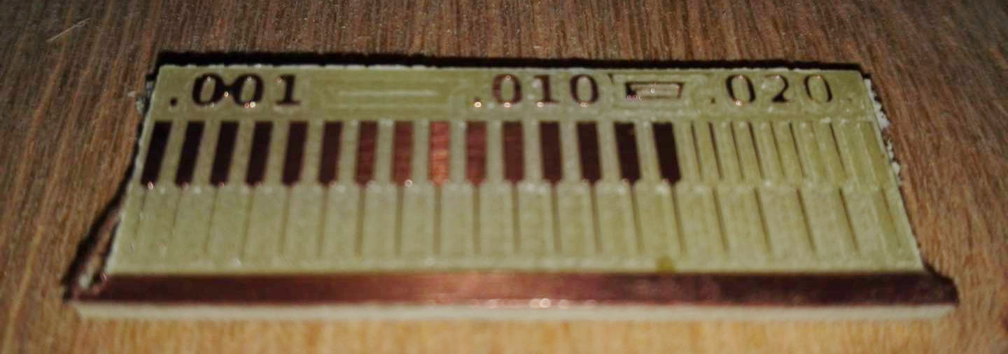
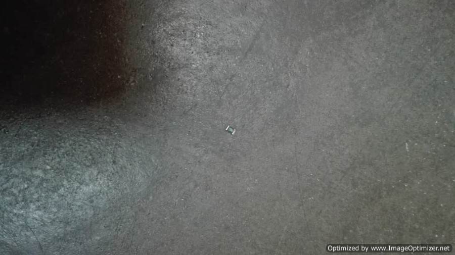
In this practice, we learned how to configure the traces and cuts of the pcb on the FabModules page. The milling tools my laboratory has are 1/64, 1/32 and 0.01 mm. We decided to make some test boards to practice welding. When making the test pcb board, we observe that the bed of the machine is not uniform. This was a strange problem: a small piece of pcb board was the culprit. Here we were able to practice the process of generating the routes with the fab modules and milling with the machine. With the pcb test board already made, I made welding tests, so that in the new board everything comes out of the best.
| Milling the PCB | Fab Modules | Practical pcb boards | Cut PCB of practice |
|---|---|---|---|
 |
 |
 |
 |
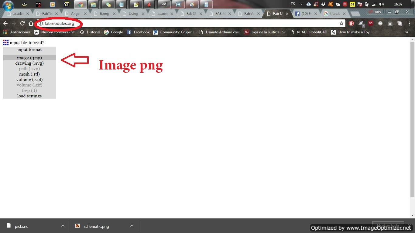
Take the test file but we found a problem, when generating the file in http://fabmodules.org/ and in http://mods.cba.mit.edu/. Here I leave the files for analysis, the scrolling speed is very low when generating the file at http://mods.cba.mit.edu/.
.png)
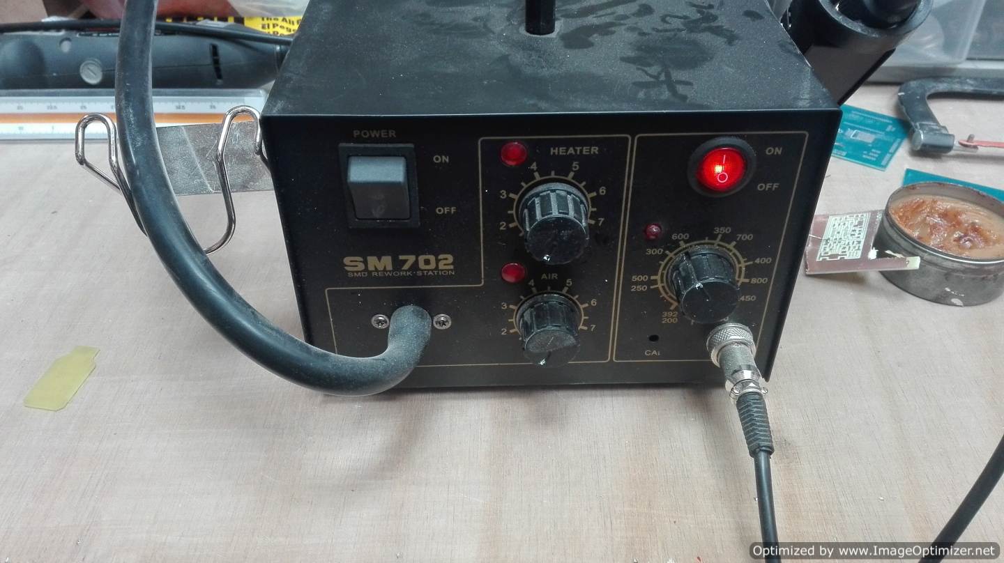
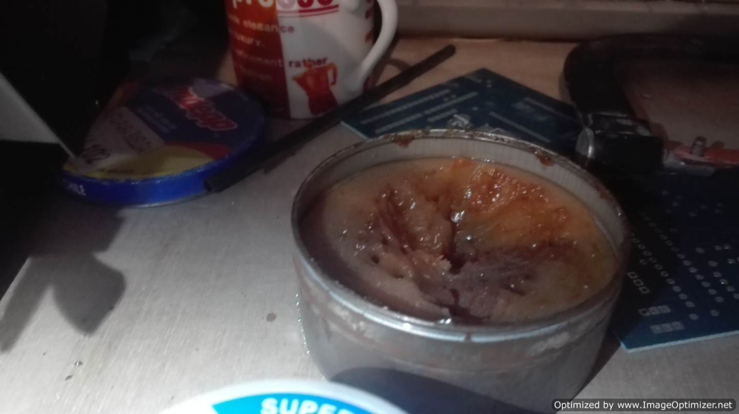
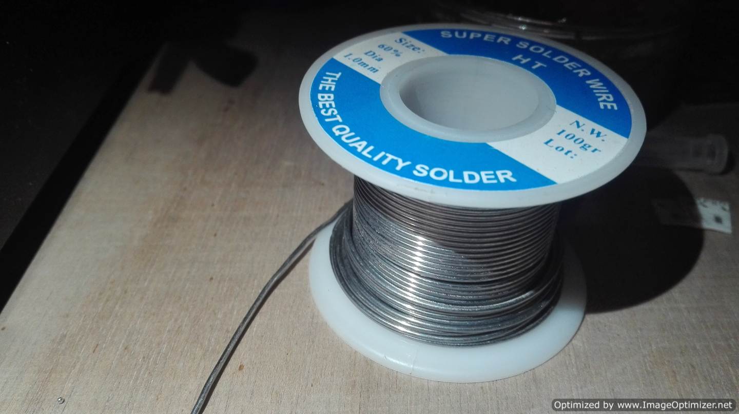
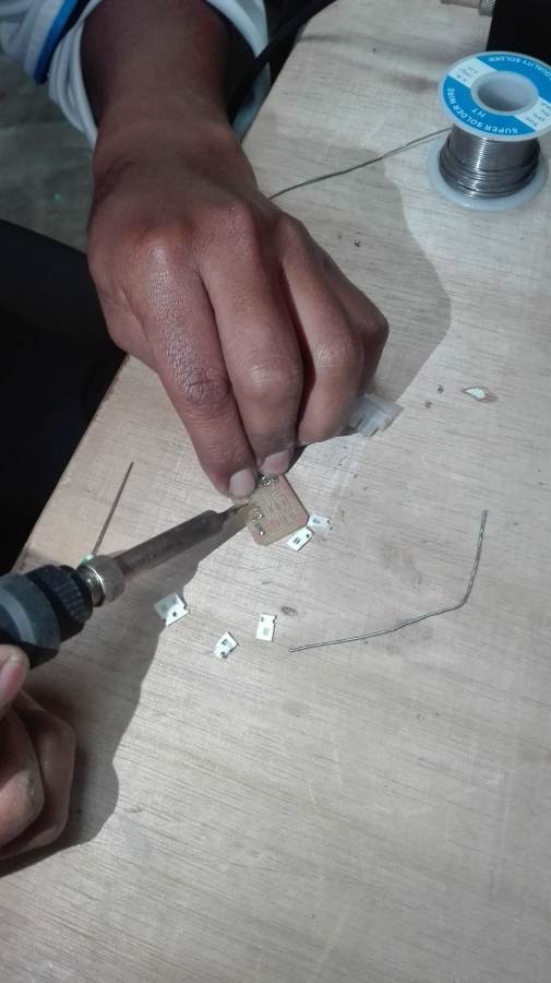
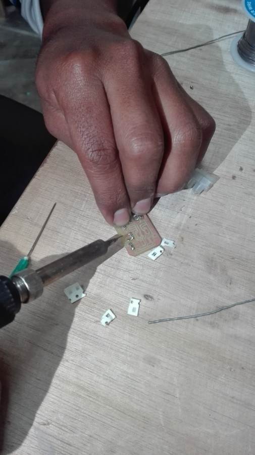
We identify the welding station and the components for a correct welding. The components are the solder paste, the soldering iron, the solder wire and the heat gun. There are more tools for the soldier but the ones I mention are the most necessary.
| Welding station | Solder paste | The solder wire |
|---|---|---|
 |
 |
 |
Welding practice
Individual assignment
* Make an in-circuit programmer by milling the PCB (program it, so that you can use it to program your board in Electronics Design week, and in other weeks)
* Optionally, trying other processes.
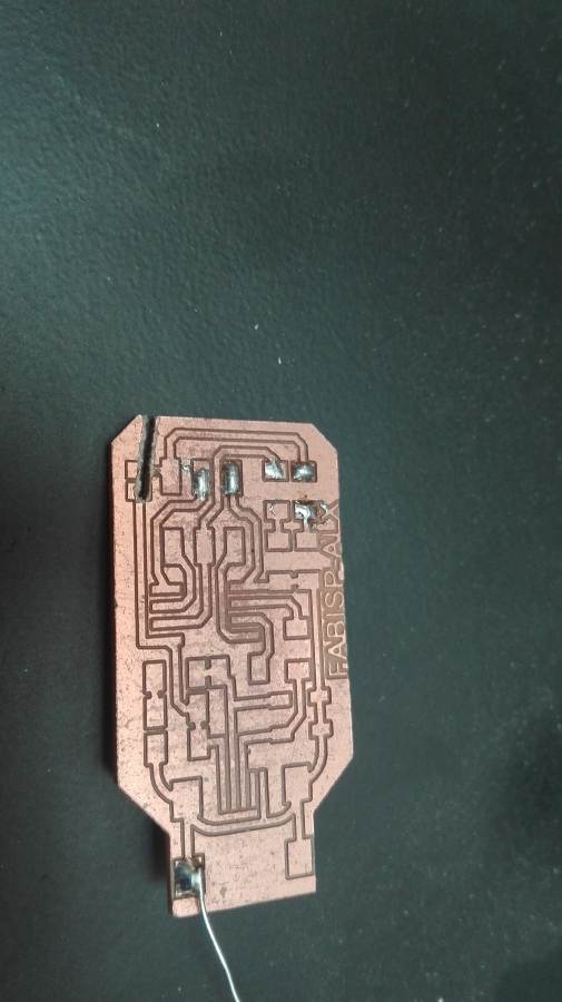
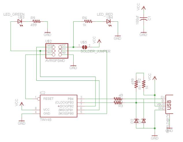
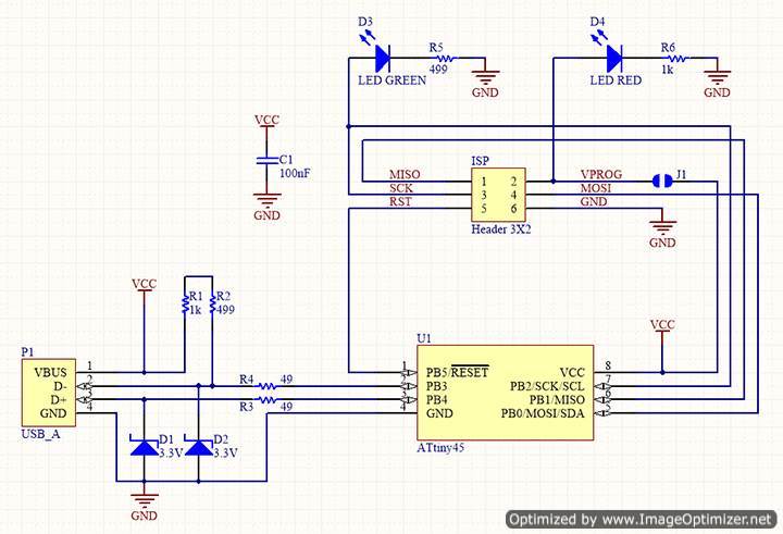
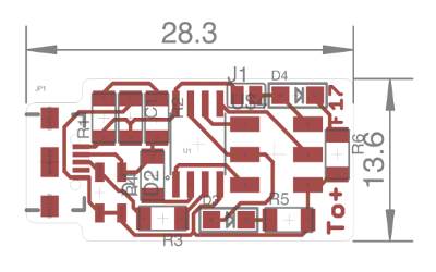
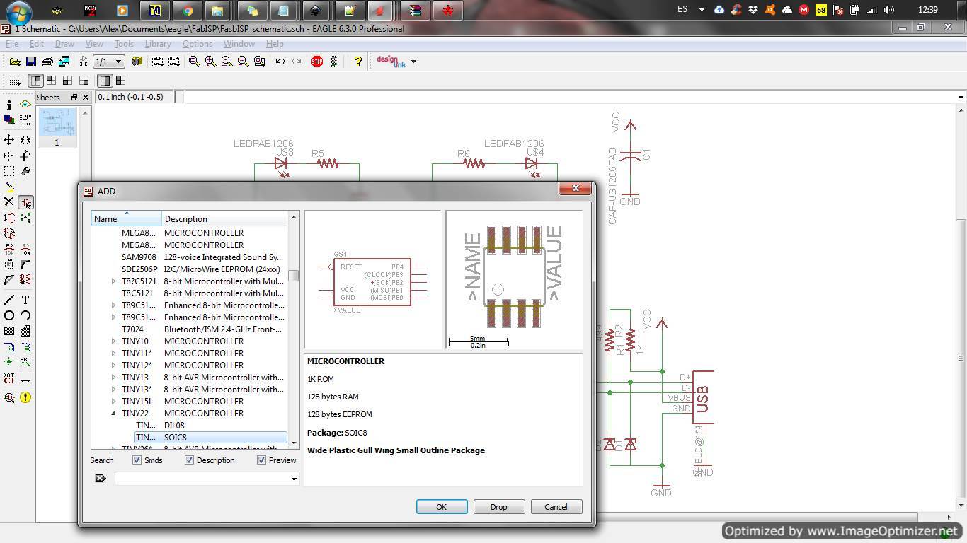
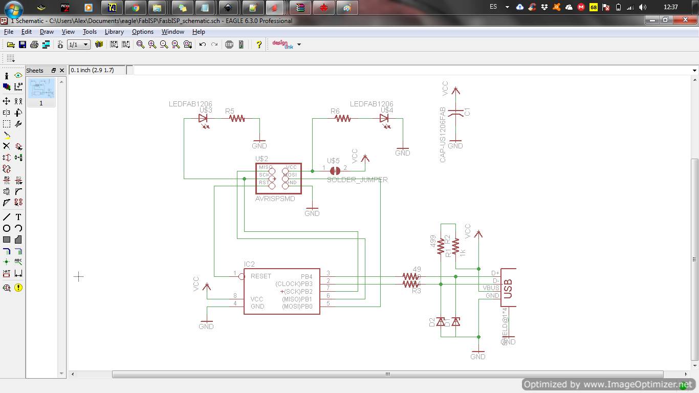
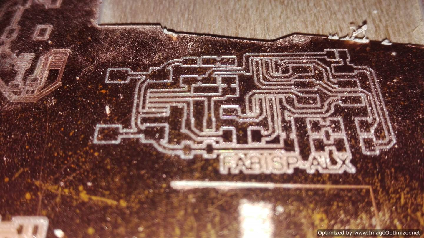
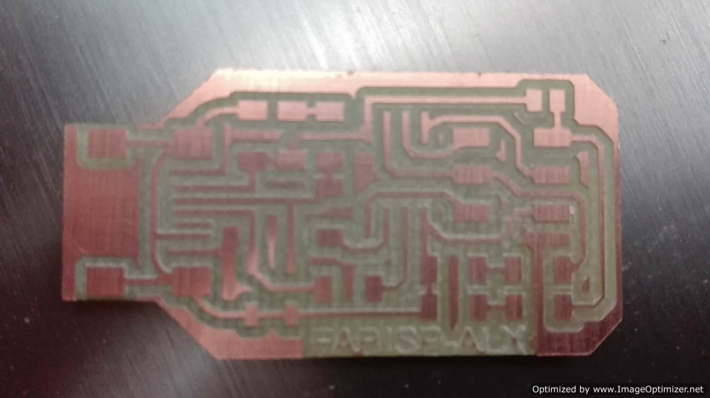
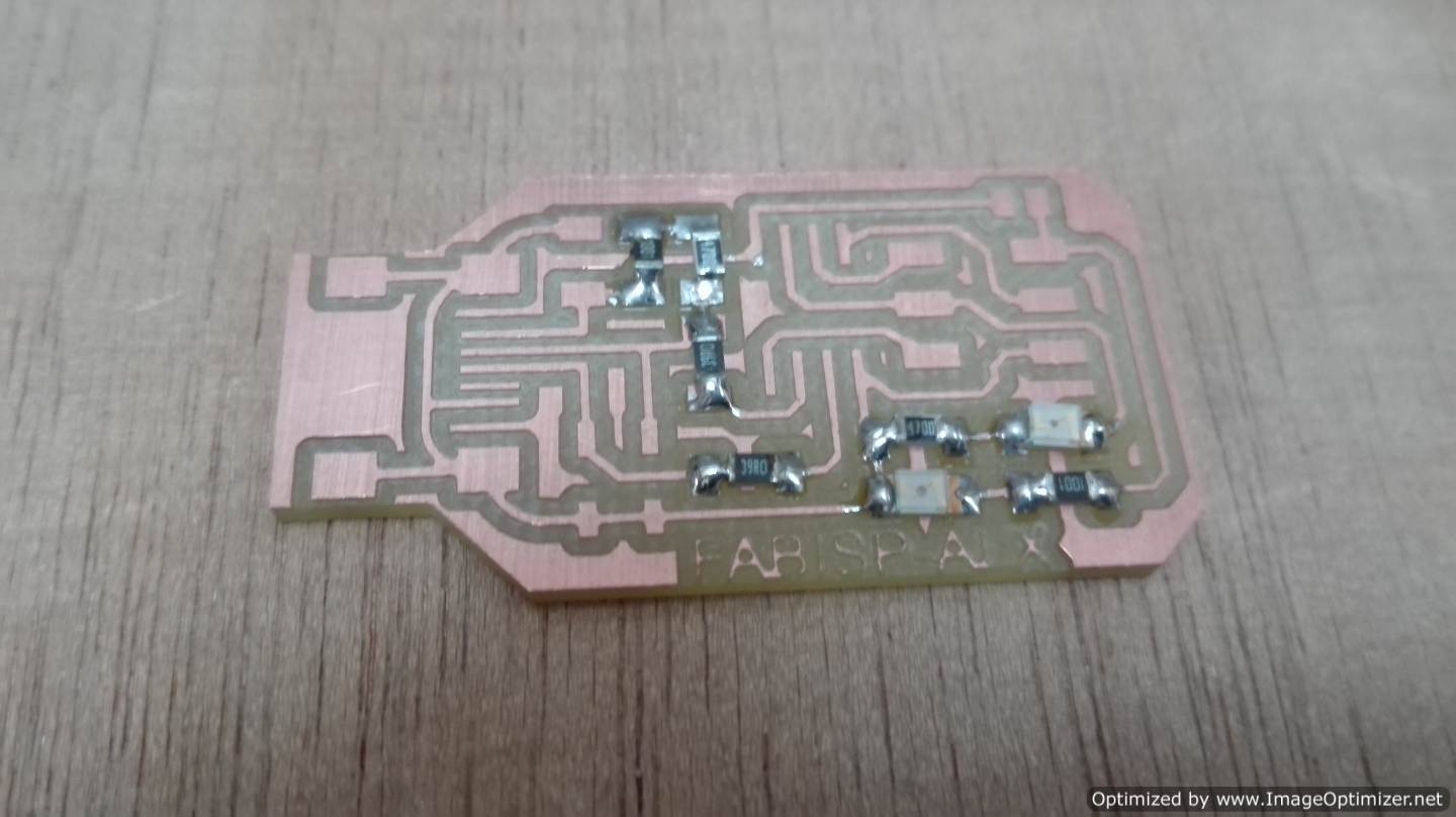
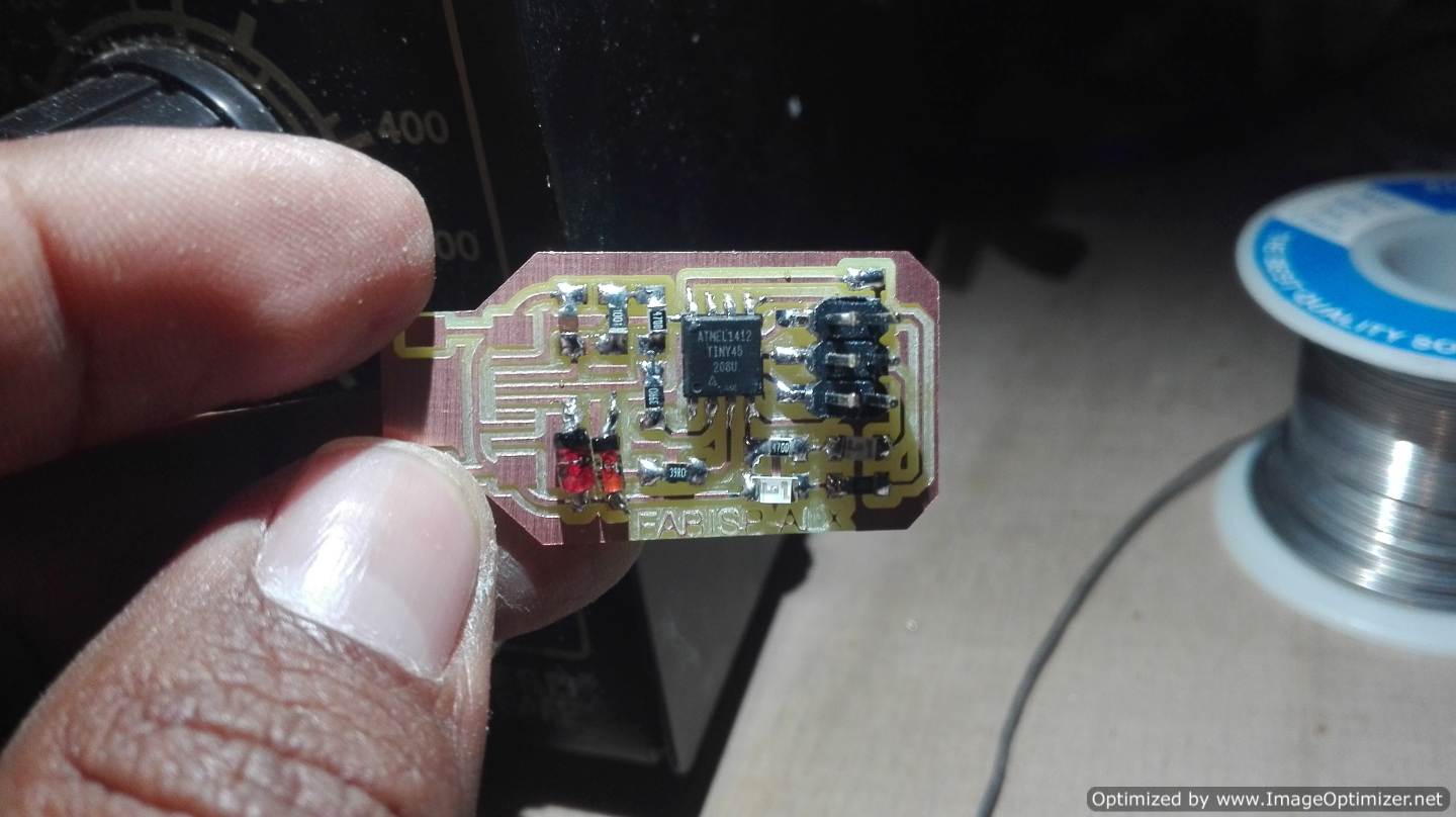
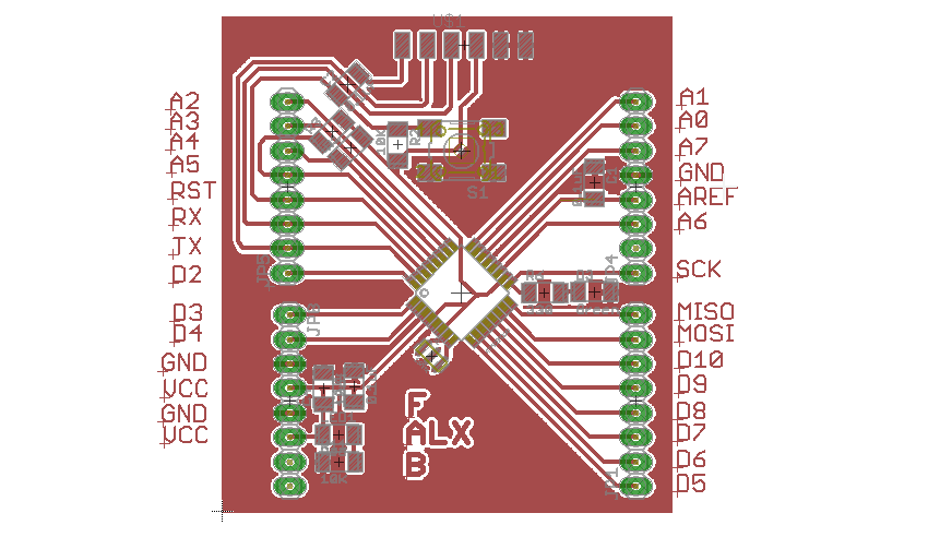
I have experience making pcb boards. I set myself the challenge of making my own PCB board, look for information on the circuit and I started from there. Use the fab library that the instructor gave me.After finishing the schematic, I made a nice design, here it took me a long time to reach my goal.
My reference ATtiny45
The USBtinyISP is another version of an AVR ISP programmer / board that can be produced in a manufacturing lab using a PCB and easily available components. My reference was Thomas' board, but on my PCB board I wanted to eliminate the errors that Tomás had when placing the bridges Page of Tomas
| My Circuit | Tomas Circuit |
|---|---|
 |
 |
 |
 |
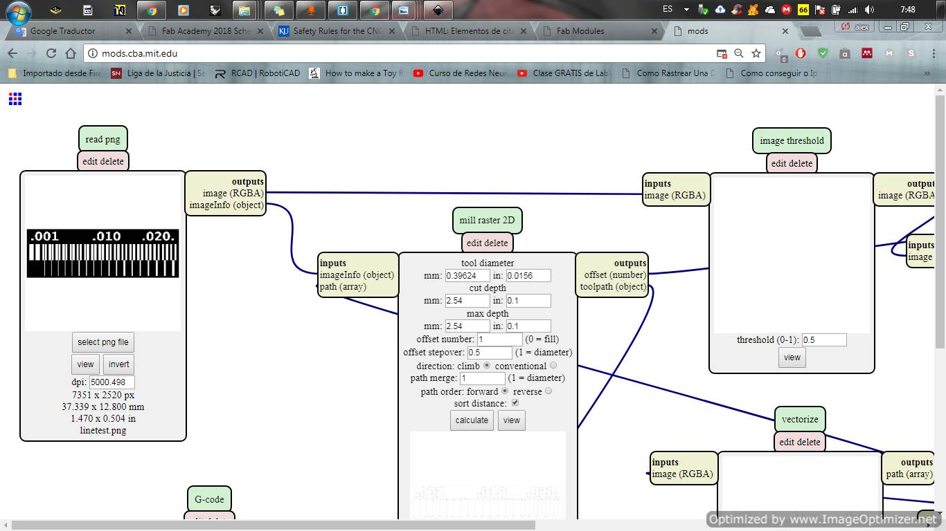
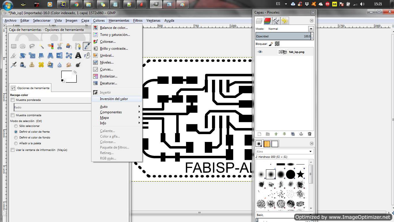
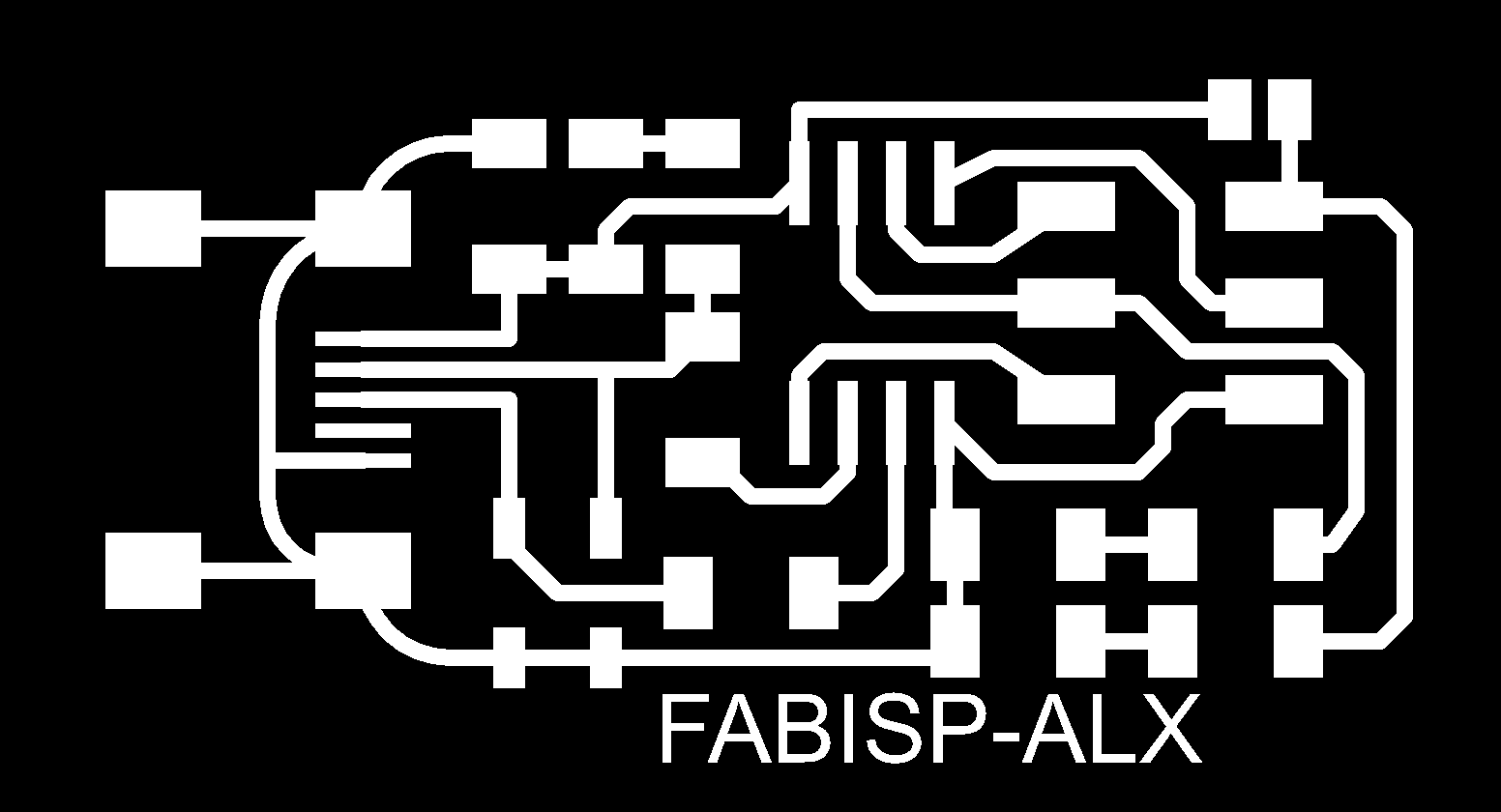
To export the file to the fab modules, you have to do one step before. We must first generate the monochromatic image of the pcb board. After generating the file, we open it with the Gimp image editor. I have to make the following changes: invert the colors, draw a border and generate 2 individual files, one of strokes and one of contour cutting.
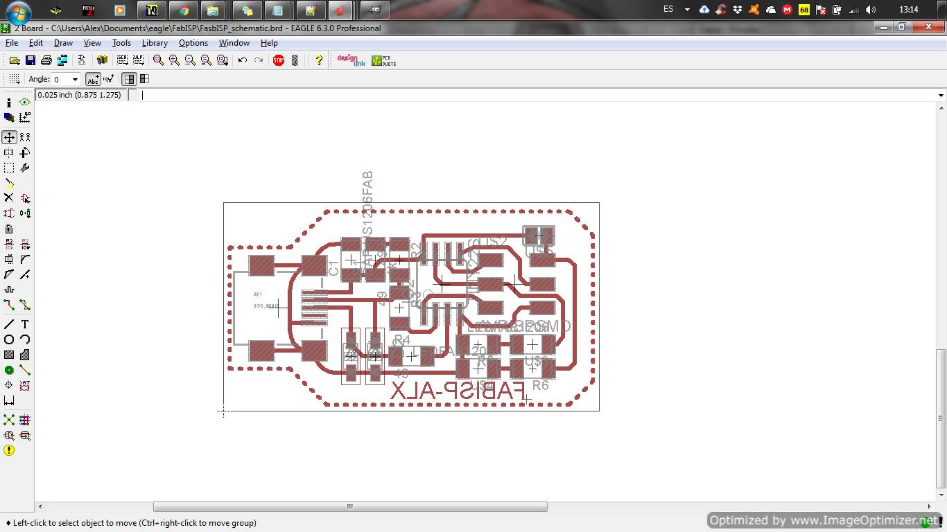
| Traces | Board outline |
|---|---|
 |
 |
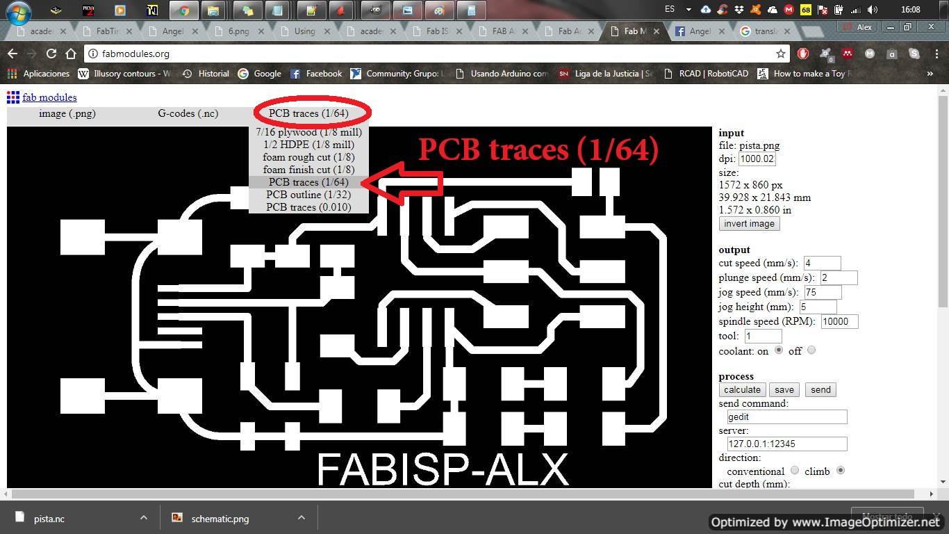
Configuration with Fabmodules
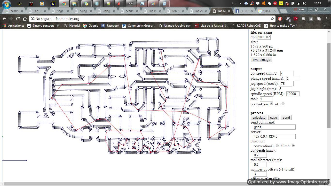
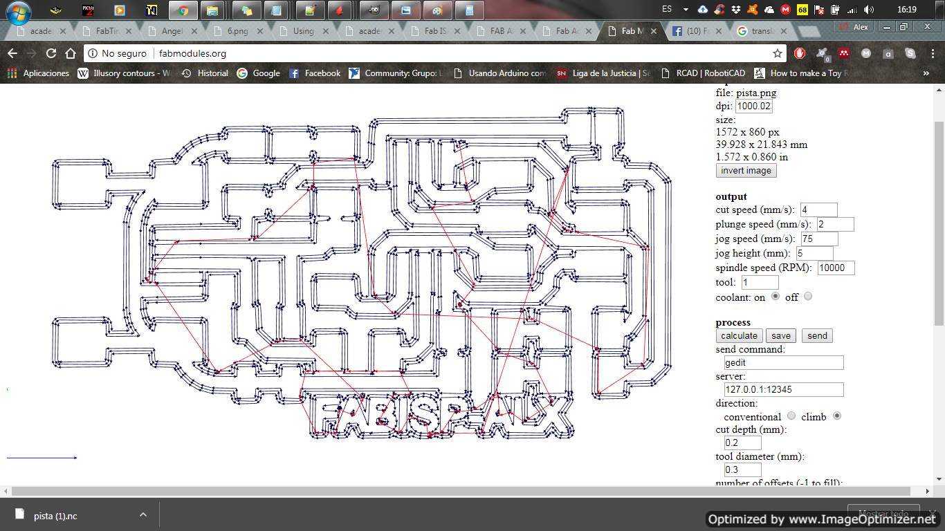
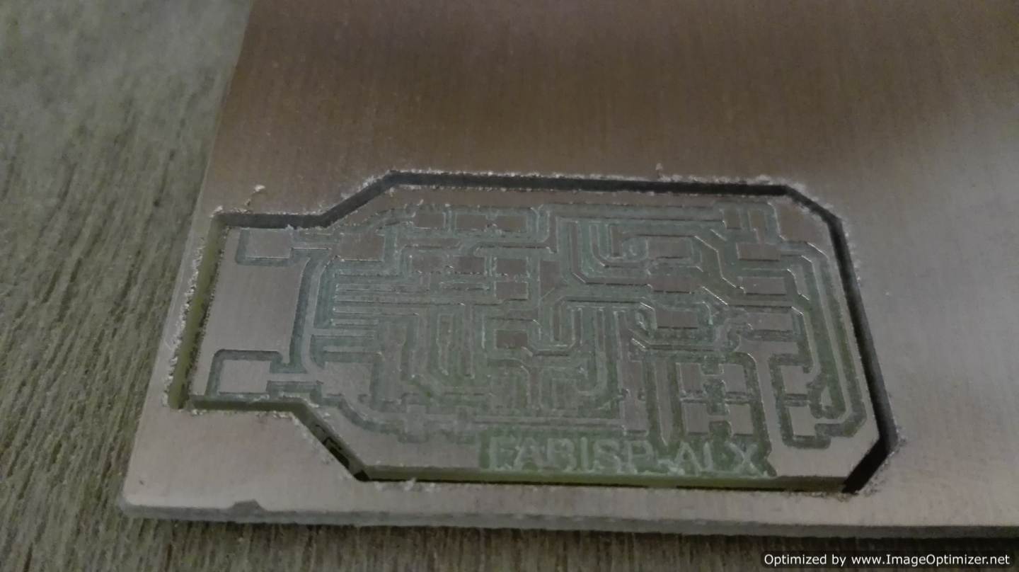
With the files of strokes and cut and ready passed to fab modules to generate my routes. Here I had to do it 2 times since the first time the fails to make an adequate route, these routes are generated by the fabmodules with The default parameters without changing any of the values. In the second way, I change certain parts where I already obtain more adequate routes and observe that it completes all the contours.
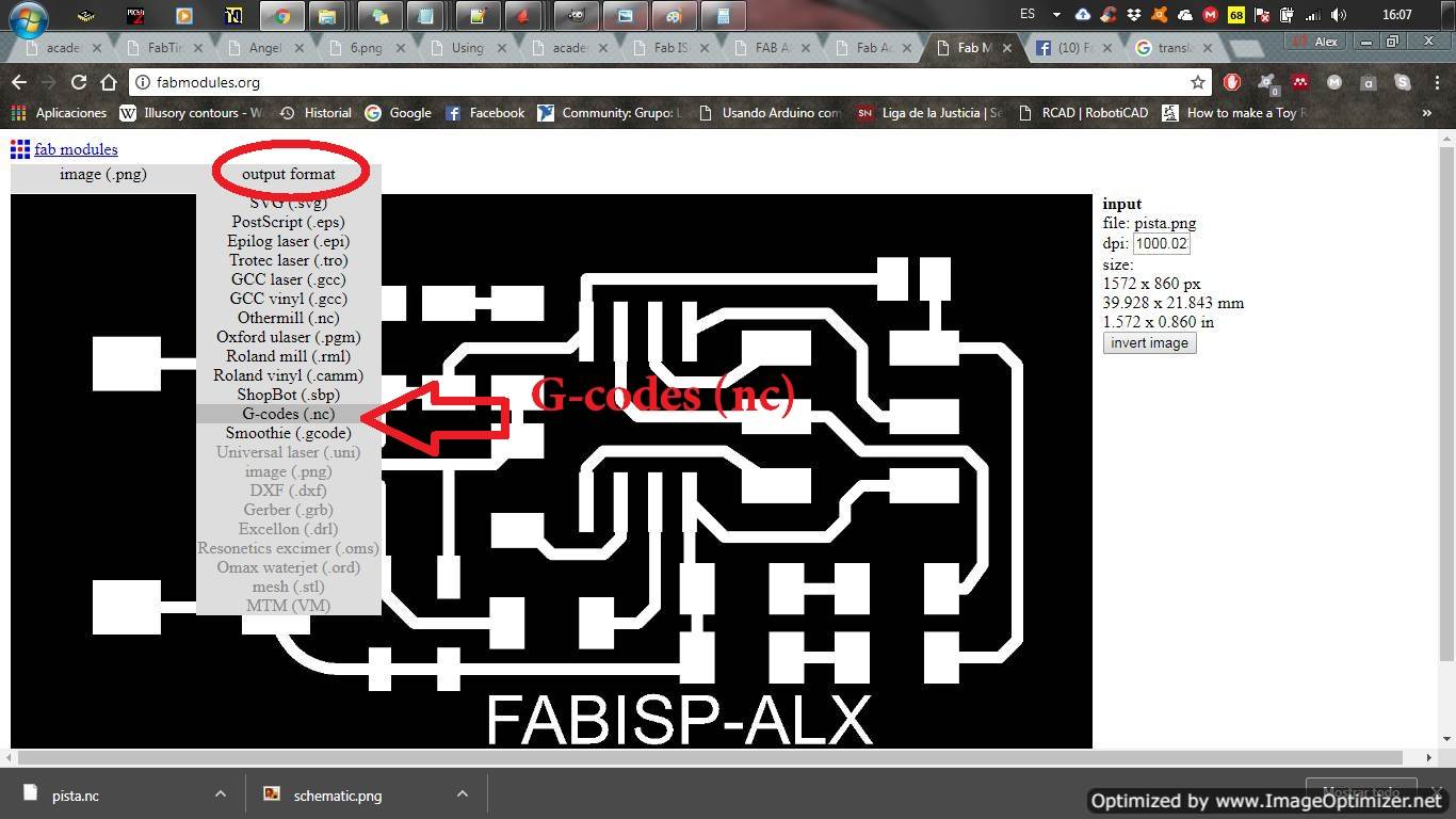
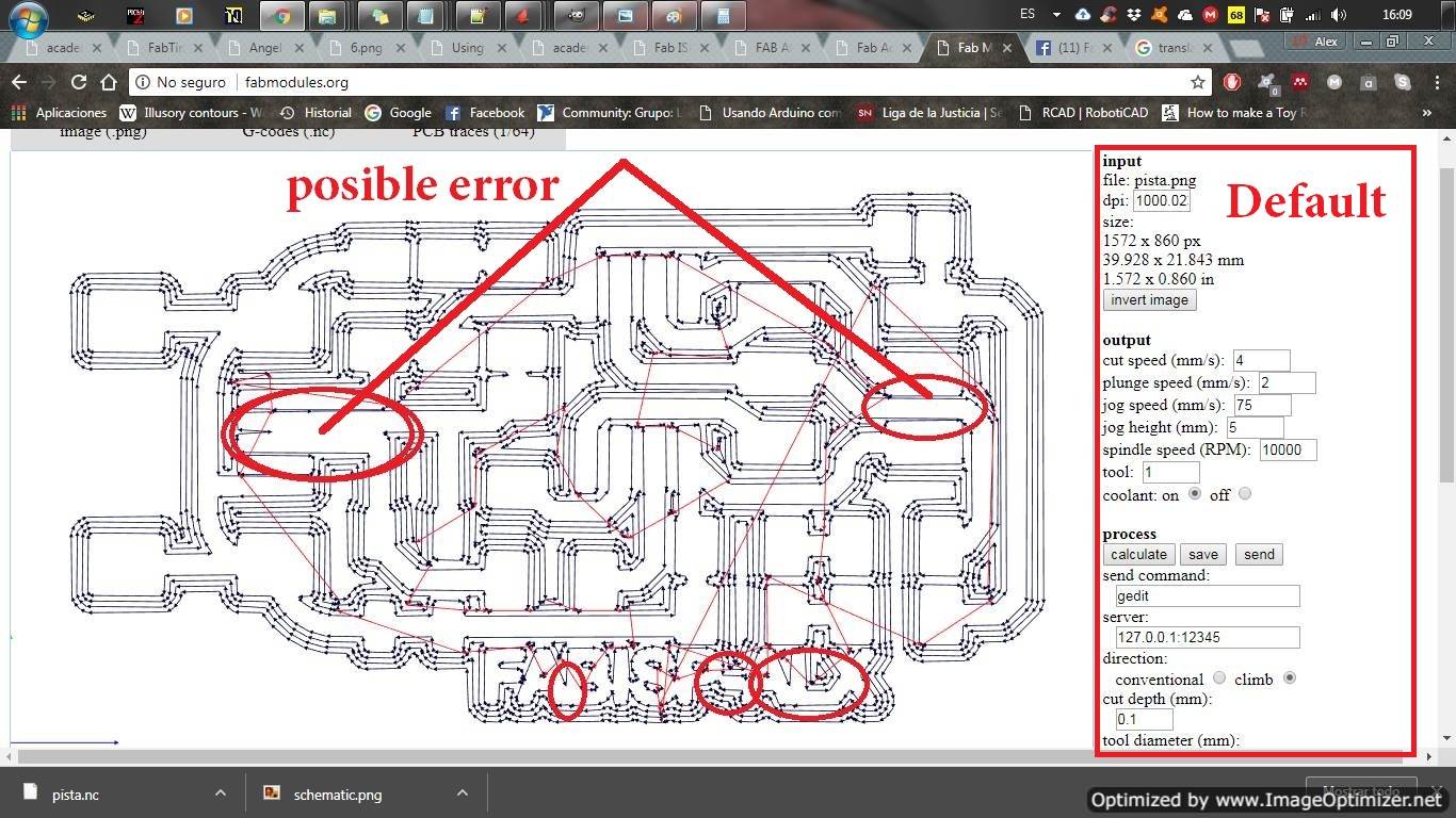
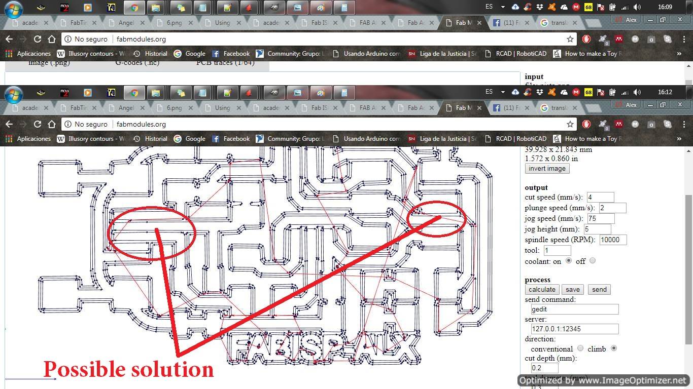
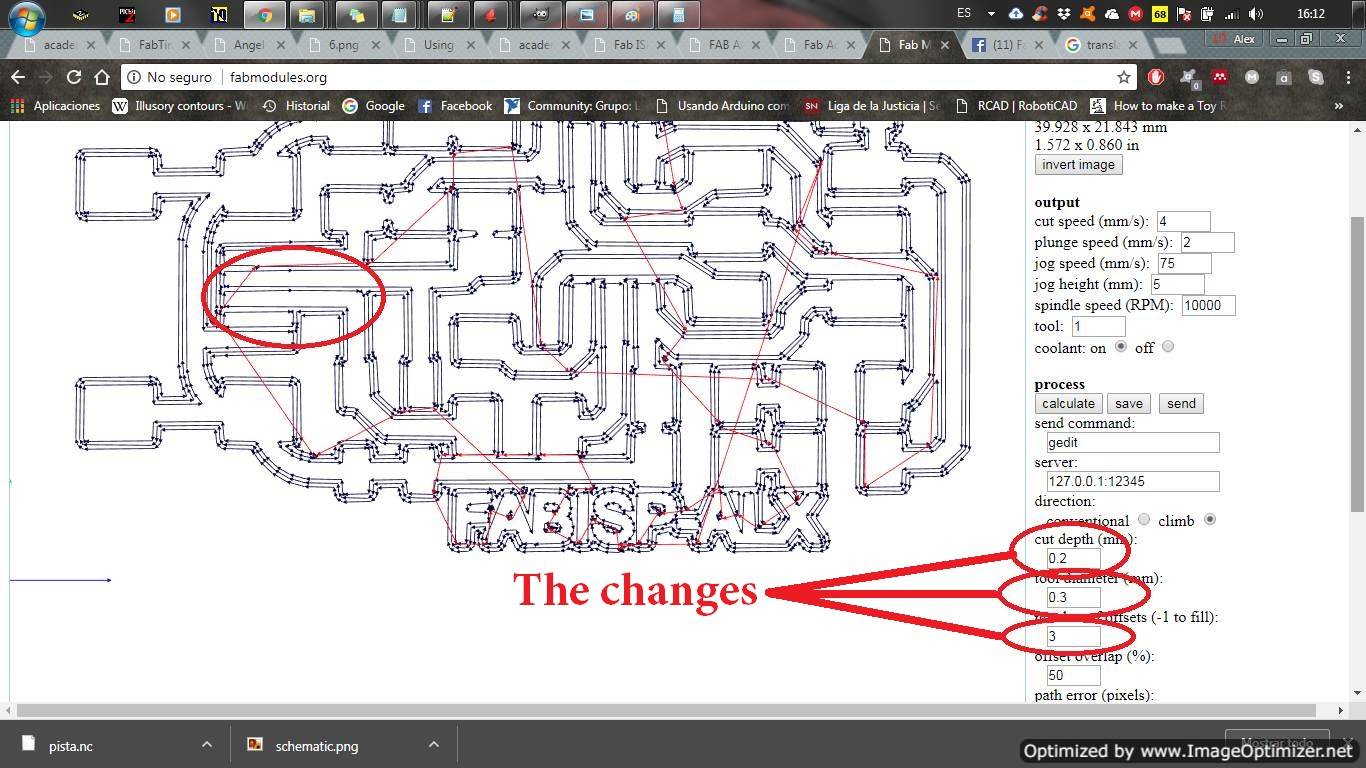
In the second way, I change certain parts where I already obtain more adequate routes and observe that it completes all the contours. The most important changes that are made with the diameter of the tooling and the number of offsets note that in the second option are in 0.3 and 3. I made an error when changing the parameter of cut depth in 0.2. This error is identified by my instructor
PCB OUTLINE
.png)
.png)
.png)
.png)
.png)
.png)
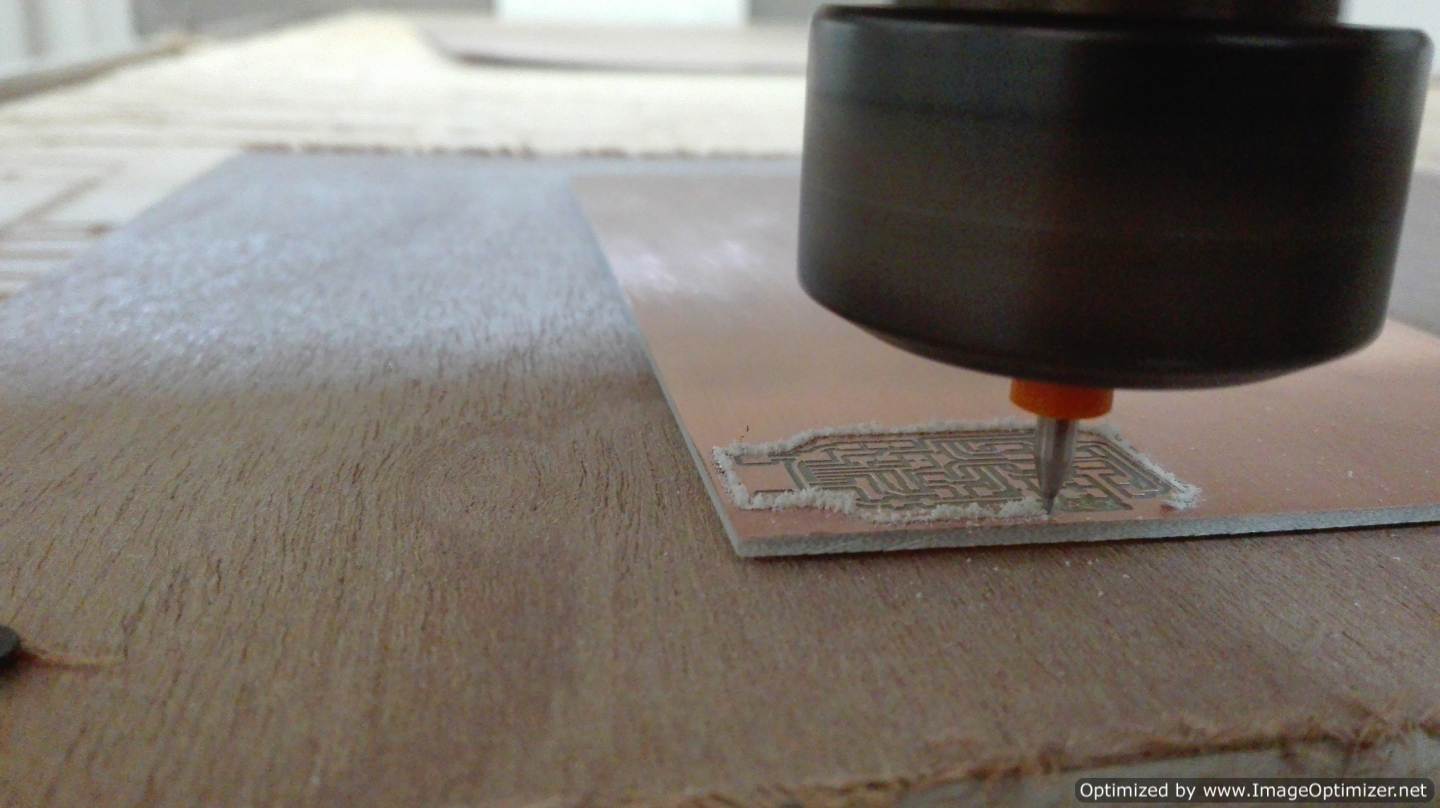
Working on the cnc machine
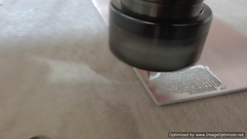
Already in the machine I use a tool of 1/64 for the traces and 1/32 for the cuts. The software that we use for the communication of the cnc is LINUX CNC. As in the pcb board of practice we made the same paste the big pcb board on the table, define the starting zero and start the process. Here I had a problem forget to place the double-sided tape. When I was cutting the outline my board got up and cut off. I have to remember to paste the pcb board well
Assembling the PCB
With the pcb already ready and correct now let's solder
The materials to be used with the following:
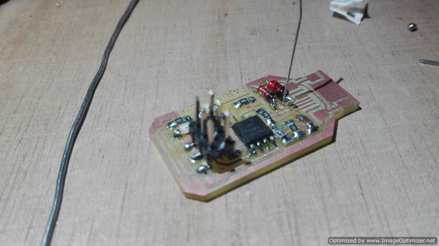
1 x ATtiny45 or ATtiny85
2 x 1 kΩ resistors
2 x 499Ω resistors
2 x 49Ω resistors
2 x 3.3v Zener diodes
1 x red LED
1 x green LED
1 x 100nF capacitor
1 x pins of 2x3 pins
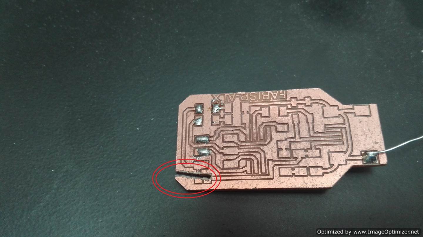
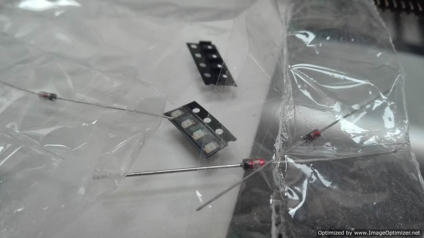
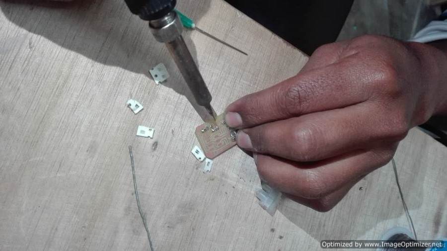
I installed the components according to the diagram. I had many problems, the components are very small. It is very difficult to weld. We did not have one of the components the two zener but we chose to use his replacement. A component fell down and for 10 minutes I was looking for the component
Programming FabISP
I use the link as a guide to programming the FabISP.
-
Install Git. Visit the link Here
Install the Atmel GNU Toolchain. Visit the link Here
Install GNU Make. Visit the link Here
Install avrdude. Visit the link Here
Optionally Install AVR Studio. Visit the link Here
About I recommend install the driver for your programmer, the program Zadig - Update the path.
- Test the program´s in my computer.
- Create the files
To start I need to install the following programs
Go to the Start menu and open the Control Panel, then go to System. From the left panel, choose "Advanced System Settings". Under the Advanced tab, click the "Environment Variables" button.
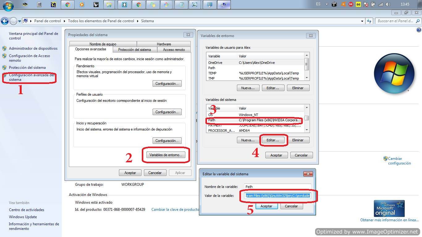
In my case add the variables :
C:\Program Files (x86)\Atmel\Atmel Toolchain\AVR8 GCC\Native\3.4.1056\avr8-gnu-toolchain\binC:\Program Files (x86)\GnuWin32\binC:\avrdudeFirst open Git Bash
.png)
.png)
Type the code make -v and next type de code avr-gcc --version
.png)
.png)
If your answers are similar or equal on the screen, the program is correct. The next steps are to create the files for the FabISP, these steps are very difficult, so pay attention.
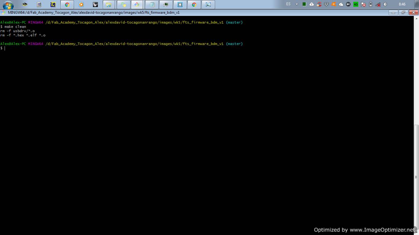
Connect the programmer to a USB and type the make -clean next type avrdude -c usbtiny -p t45 remenber press enter. I'm trying to program my fabisp with another programmer with the name USBasp.
.png)
If in the second step see the code initialization failed, rc=-1 this is the solution for windows in my case.
Change the name of the programmer according to the one shown in the equipment manager. If the error continue , try the next step. Open de Makefiles and change the name in this files.
.png)
.png)
Change the name of the programmer avrdude -c usbasp -p t45 . if the process is correct. Type the make clean
.png)
.png)
Type the code make flash . Remember edit the makefile .
.png)
.png)
Type the code make fuses . And finally type make rstdisbl .
.png)
.png)
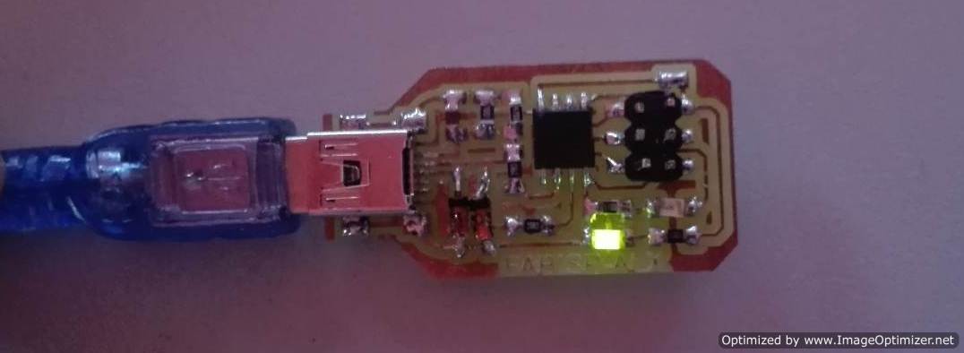
Now I have my Fabisp.
My FABALX.
Additional in this week I created my FABALX is a new board similar to arduino pro-micro I use the bootloader of arduino Pro-micro the reason is that i prefer use the ftdi for programming and communicated
In this week I can only mill the board. In other week continue with the programming
CONCLUSION
A large machine can make very small circuits all depend on the accuracy of the equipment in our case is great the machine is very useful to capture its large size.
The pcb board that neil asked us to do the test showed us 2 very important things something strange happened with the mods, the drilling speed in z is very slow, another conclusion we saw in our machine, because this is too uneven.
Many cnc correct the level error using auto level programs as in our case we use AUTOLEVELLER.
Most circuits are made in eagle a tool that many makers use, I also realized that most students do not upload the original files but upload the photos of the schematics this sometimes delays but it is good to learn how to design.
Something very important for me was discovering that you can do a programmer for only about 3 dollars and a very small size, even with this I discovered how to program from the console.
Something that I loved was that Neil liked my PCB silver all my colleagues bother me for that now they tell me ALEX version. He said that it would be a reference for the prosy academy.
Something very important that I learned was to handle Make files I had never done this, I had not been able to program from the terminal now I have the idea and soon I will continue discovering more things