Materials, tools and software
Shopbot Full-Size(Tools)
MDF (Materials)
Autocad (Software)
VCarve Pro Shopbot(Software)
 |
 |
 |
 |
|---|
Shopbot Full-Size(Tools)
MDF (Materials)
Autocad (Software)
VCarve Pro Shopbot(Software)
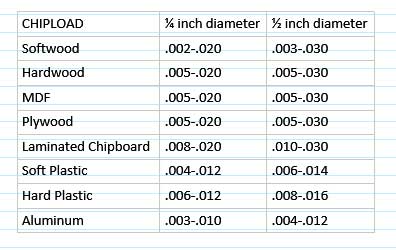
To generate good CNC cuts you must select the best cutting speed (feed rate) and spindle RPM. The "chip loading" can be a
vitally important value with which it facilitates the configuration of the process. This data can be facilitated using the
guidance provided by the manufacturers regarding the best "chip loading" for a particular cutter. Since the chip load reflects
the combination of how fast the cutter moves toward the material and how fast it rotates (Chip loading = Feed / [RPM x number
of flutes]), it gives you starting point speed values to perform tests to determine the most appropriate parameters for any cutting situation.
More specifically, the ShopBot chip loading calculator simply provides a quick way to explore these values, and it is
more advisable to know the approximate desired chip load for a particular cutter and material.
Keep in mind that the most effective chip loading depends on the specific geometry of the tool, so you should consult
the information of the manufacturer of the specific tool and then maintain your own parameters and settings on which values work best.
In the same way we can find more information about information on tools, materials and configurations at
Other configurations within which we can the depth of cut = 2x diameter, reduce the chip load by 25%. If the depth of cut = 3x diameter,
reduce the chip load by 50%. Note that there is a considerable overlap in the parameter range and this indicates that you should test
the best speed selection for a particular cutting or machining operation. Here is the strategy suggested by Onsrud:
1. Start using an RPM derived from the datasheet base for the material you are cutting.
2. Increase the cutting speed until the quality of the finish of the piece begins to decrease or the piece begins to move. Then slow down by 10%.
3. Then decrease the RPM until the finish deteriorates again and then raise it again until it is acceptable.
4. This optimizes the RPM and speed so that you are taking the largest possible chips.
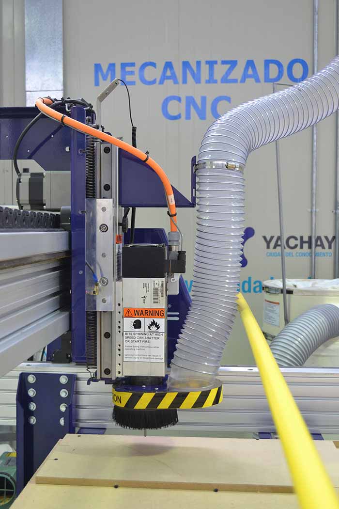
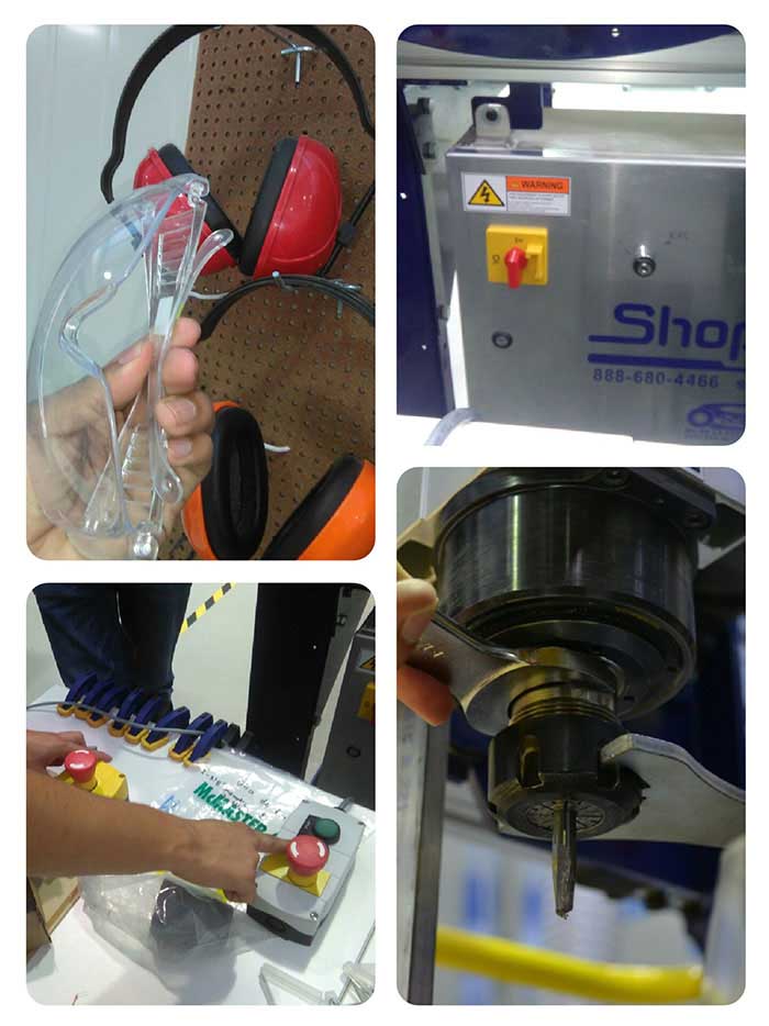
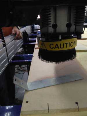
Before you can use the machine remember to always keep in mind the following steps.
-Check switch OFF and the variator frequency ON
-Put the material (wood) on the table of the machin with screw.
-Select the mill of the chosen material
-Use protection instruments such as glasses and earmuffs.
In this part make functional test. We introduce a piece in which we can make calculations to prove the current
operation of assemblies for different applications.
In them we also perform the different tools for assemblies with this we can know the correct operation of each one.
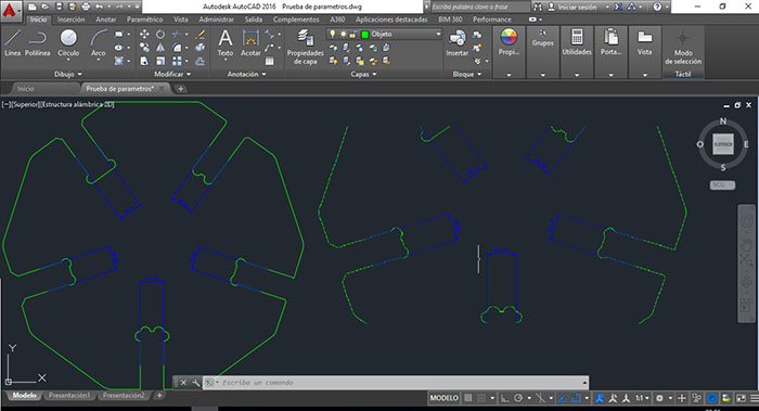
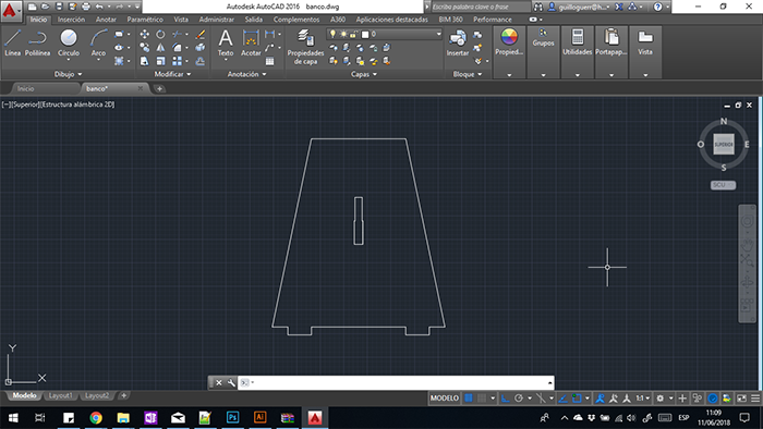
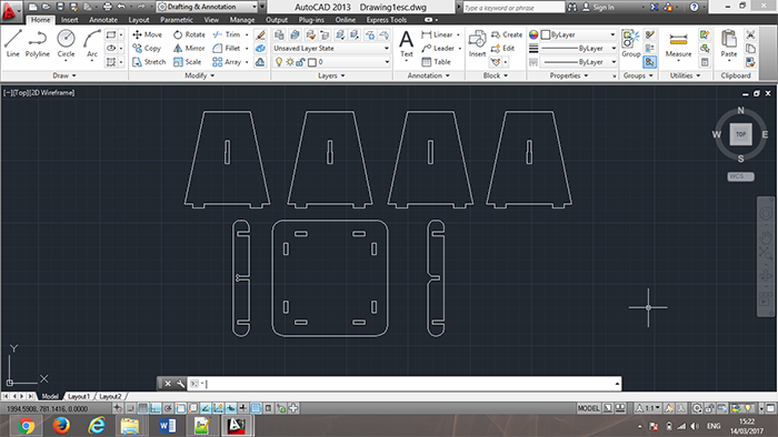
The file is designed with basic 2D design tools and constraints based on the thickness of materials that can be
contaminated in the laboratory for the power of furniture design.
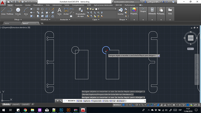
For the realization of the pieces polygon tools are used as we observed the first box of the image after the rectangular
tool and finally the circle with which we generate the details of the assemblies.
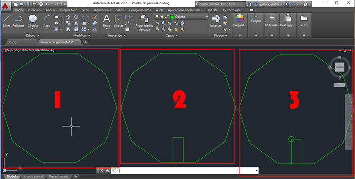
As a last step we use the clipping tool to give the details. This process is repeated on each side of the polygon.
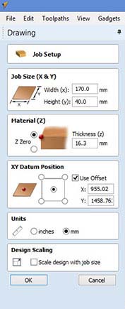
To be able to export to the software of the machine we save the (.DXF) file and proceed to the configuration of Vcarve.
Open the VCarve Pro Shopbot Software with the piece and change parameters for "X - Y" axis then put on 0 the "Z" axisfor this put
on the matirial the sensor and check the clamp is making a ground connection (the mill must touch the sensor). Select the unit
to work
In the next part select the toolpath options for this work I select smooth out of the piece. then take the correct mill and the correct
direction.
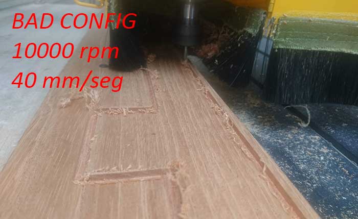
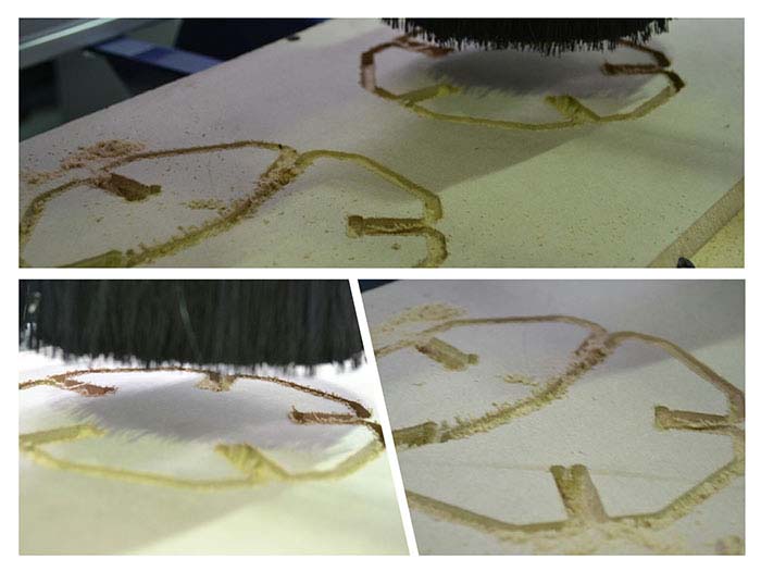
The next example we dont select the correct mill, this caused errors of the units in the piece.
for the machining the file had to change the correct mill.
In the development of the tests of the machine, we generated an error in the file as it can observed in the next image so that it took to make a review of the machine where an fail was determined in an update by which to solve it it was proceeded to uninstall this update and proceed with the normal operation of the machine.
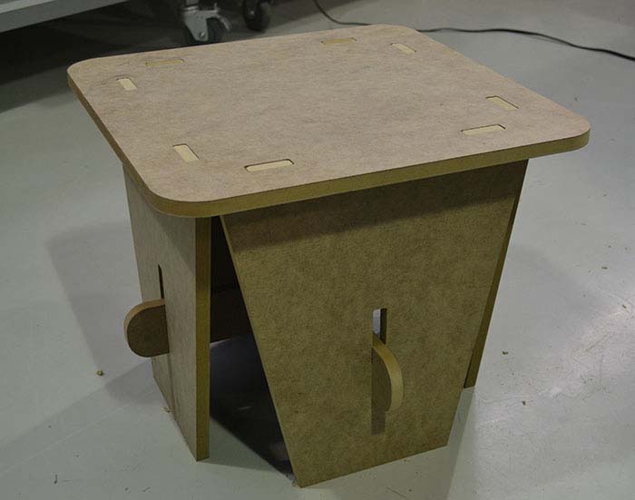
with design the new project I take ergonomic measures and make a bidimensional object with pressfit,make a sacale model in the cotting laser.
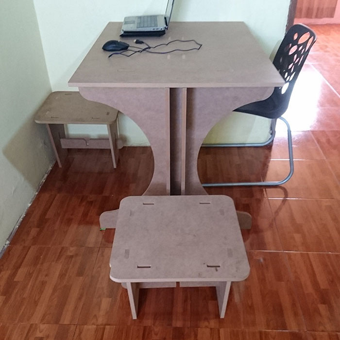
I used this software for the design. In which two-dimensional files were designed which, when joined together by a system of pressure assemblies,
form a fully functional three-dimensional object which was installed in our department together with the design of my brother's table, generating
the complete set.
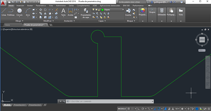
For the design of the first piece, the line tool is used to redraw the entire contour of our piece for the design of the assembly measures, design
them in the same way as detailed in the previous process based on the thickness of the material in this case 16mm.
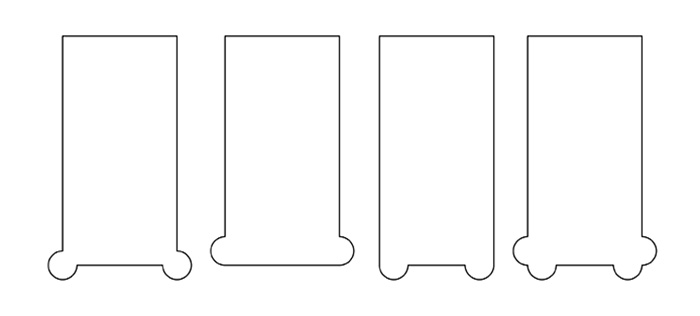
These pieces will serve to give more structure to the bases, to develop these pieces we use the tool of rectangle with its rounded tips so that they do not hurt the person. without forgetting all the details in the assemblies for which it was developed with the circle tool on the edge of the rectangle and to generate that these are made in a single piece with the cutting tool.
and finally the design of the base is nothing more than a rectangle of equal shape rounded the corners so that it does not hurt the person.
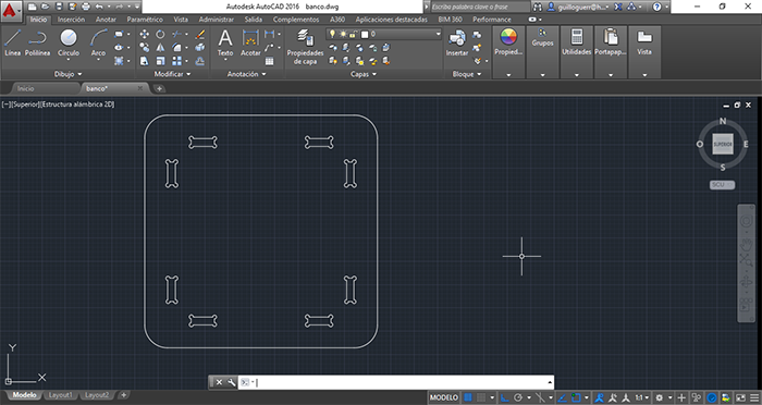
We can see all the pieces together ready for the next process.
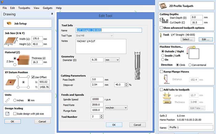
First we configure the parameters in the axes as explained above.loading the dimensions of the material that we are going to use.
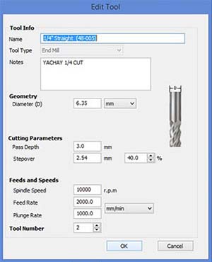
Next step is to choose the right tool for the type of material, for this case we will work in wood and we can therefore recommend a
Flat Mill of two flutes.
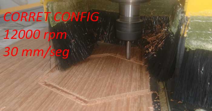
The correct configuration is the following:
FEEDS AND SPEEDS
Spindle speed: 10000 RPM
Feed rate: 2000 mm / min
Plunge rate: 1000 mm / min
CUTING PARAMETERS
Pass depth: 3mm
Stepover: 2.54mm
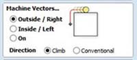
then once we have configured the file we import in DXF format and we choose the last configurations for machining. We choose if we want the configurations to be inside, outside or on the line we save the file and proceed to the machining
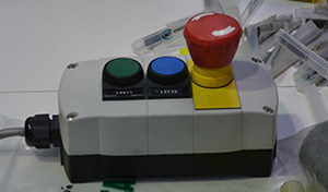
ALSO REMEMBER MEASURES OF SECURITY CONTROL OF THE MACHINE.
stop buttons for the machine.
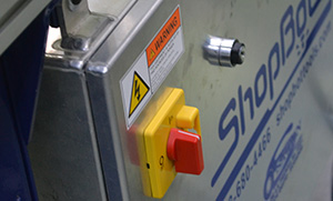
The buttons of ignition and the key for ignition and control of the spindle and others that were detailed at the beginning of the documentation.
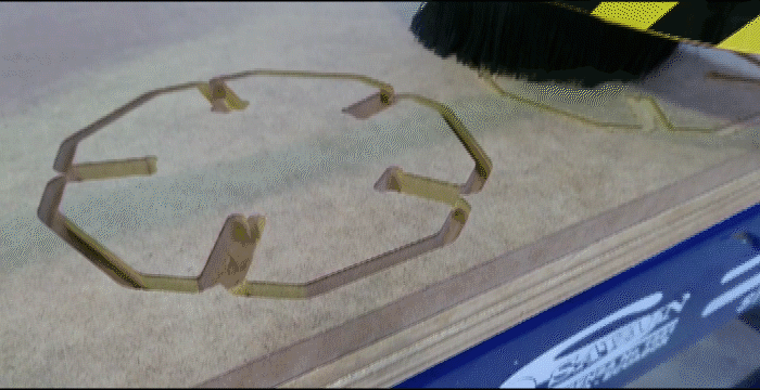
Once arranged to start the process we fastened the material in the bed this was done with screws and drill. then we load the file as explained above and generate the cut as can be seen below.

For the development of this object 1.6 mm MDF is used to be structural and resistant.
In the following image you can see the object already assembled in an appropriate way and installed in the department.
The table was made by Juan Guerra for his assigment, in the next link can see his work