For this week, I try to make a driver of stepper motor, I based to circuit of the Marta Verde, but in the fab lab not in stock a regulator direct a 5v, I adapted a regulator variable at 5v and adjust the circuit, for this first find out about the regulator variable, you can find this calculation in >>datasheet<< and chance this in software eagle.


The regulator is smaller than the one that occupies and for this chance y make the next commands in the circuit.

First the regulator is variable and need a circuit to regulate a 5V and for this you can know in the datasheet, when this data you can calculate the value of the resistor to the regulator give 5V.


The first change is in schematic, delete the previous regulator and add all the components we need.
Next use deafferents commands to edit the plaque: move, net, label. The first command is to move the components, with the second use to connect all the components and the last is to give a name at the line that connect the components.


The next part is edit in the board to finish, the commands to occupy are: move, ripup and route.
The command move is the same as the previous, the command ripup is to delete the traces or also you can delete with the button “delete” or “supr” and with route is for connected all the components that pointing the yellow line.

In the second test I based the design to Hello board but modified.


In the second test I based the design to Hello board but modified.
To modified I use Eagle, add the next components pin head 2x2, 2x3, 1x6, attiny 44, capacitors, resistances and driver A4953.


Based in the hello board, next make the design of the board use the button group, move, route and ripup.

first time I did the board I make various mistakes, first I forget the pin to energize the plaque, in the connection with the pins of the driver and in the moment to unsolder the components I broke the traces and hurt all the board.

For taste the motor driver A4953, I simplified more the circuit omitting the regulator and one diver, all the changes first in the software eagle and add an angle header, this is to polarize the plaque at the time of burn bootloader and the program, in the first circuit have a problem whit the plaque because the tracks joined and I could not find it, in the second circuit the design is right and can program it.


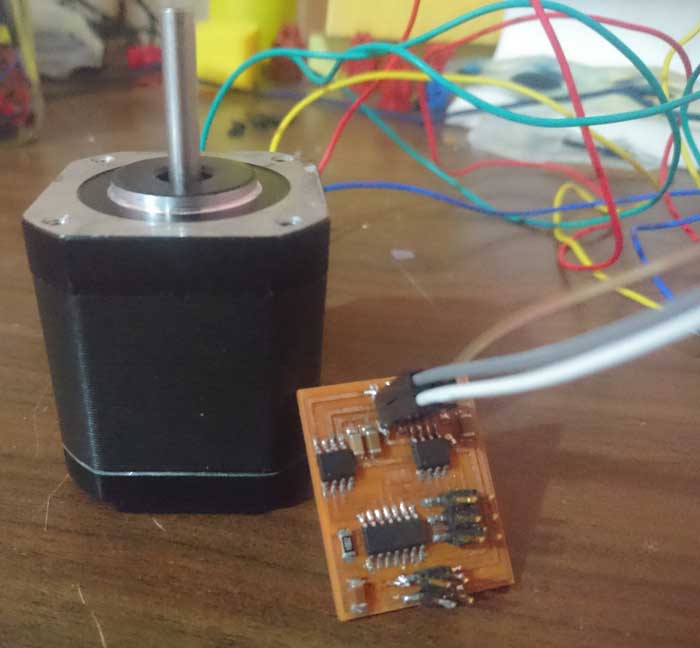
The driver program will try on Arduino, the driver make is control the pulses that are for each bobbin, the motor has two bobbins and the pulses is for one at a time, we try to do this process in programming but the motor does not spin, the only thing we achieve is that the motor is enclave, the plaque is in correct operation what does not complement it is the programming that does not achieve the rotation of the motor.
The components that the board has are one microprocessor, this component contains all the programming of the functioning of the board, drivers to control the pulse and direction of turning and speed, and a regulator of 12v to 5v, finally resistances and capacitors.

All the process you can see to star the page and described the errors with all the errors in the boards and the programing.
The process you can see in the top of page, this process shows some test for the boards for test and the process to programing too, all this show with images and screenshots.

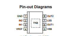
For the datasheet placed the link >>HERE<<, with this you can guide and see that pin need for the programing and how the driver works also how connected the pin with microcontroller and the driver, and the datasheet for driver >>HERE<<.
the problems in the plaques you can see and the boar repair and with the program is an error in the moment to find logic to program, only you can be like a flicker you should activate and deactivate when send a signal, this error is fixed up in the file.

connection of the output board with the oscilloscope

pwm signal of the motor driver generated from a maximum voltage of 12v.