


You can find the technical data sheet in this >>link<<

You can find the technical data sheet in this >>link<<

you can see the safety data sheet of a plaster in this >>link<<

the safety data sheet of the material paraffin wax is >>here<<

the safty data sheet of the Urethane Rubber >>here<<
For make the different test first see the warnings of each material in the safety datasheet, in the datasheet you can find very important information to considerate of make the mold.
recommend using gloves and masks as it is very damaging to the skin and a lot of damage at the time of inhale it.
In the safety datasheet of plaster, it is recommended to be at the moment of handling, caution should be taken when mixing it because it normally heats up at the moment of reaction.
The affections are because of its irritating properties, may aggravate preexisting skin, eye, and respiratory conditions.
With the paraffin, be carefully with your eyes, in case to ingestion do not induce vomiting, recommend drink plenty of water and if possible drink milk afterwards.


In the assignment I design the mold in the free software fusion 360 and make the process to get the g code in aspire, look up to the image for the results of the two software.


Open Fusion in a new design, select in the workspace the plane to the design. In my case I select z and x plane.

In the plane selected. First, create a square of a dimension required, in my case select of 150 mm and press finish sketch.

To make a block, select the sketch and press the tool extrude, in the window you can change a different parameter if you need, I only change the distance to 40 mm.


Next, for make a hole in the block, for this process in the top of the block create a sketch with a right click on the plane and select create sketch. In the sketch like the previous step create a square, in my case I make of a 70 mm.

In the sketch made in the last step, use the tool extrude to make a hole a difference of the previous step is the distance is negative to cut the block created.


In the center of hole make another cube to cut and build a pyramid, first create a sketch and draw a square, next with the tool extrude make a cube.

Finally, create two sketches, one on one side of the cube and the other on the adjacent side, like the image.


To make the pyramid use the tool extrude in each side to cut the cube and obtain the pyramid.


In a new archive, first made the configuration of the block of material with the measures. Select the height, width, thickness, position and the units and press clic in OK


Next import the file make in the previous software, In archive click in import and select model 3D.


When the file is import you can see in a window on a left, the position of the object you should select the correct to you file. If you end press in OK.


Next in the panel in the right side press and select two different process roughing and polished. In each process you must select and edit the mill tool

mill for roughing

mill for polished
When you select the correct mill tool and if you want change the different parameter press in calculate to make the trajectory

To export the gcode press in save and select the correct code for your machine and press in save trajectory.


When initialize the machine to upload the gcode go in the left panel and click in project manager, next create a new project in the green button on the top, then in the space you can drop all the files and press in save. Finally appear a name of the files in a list with a green button on the right to go a mill process, appear the controller of the machine in this step you must select the 0 point and press in mill.

To get the block, I use an old piece of cast and cut a portion.

Next, to mill, I put the block in the machine and to fasten I use two pieces of wood with double sided tape to prevent movement of the block when milling. Once select the 0 point and press in the mill button on the interface of the machine.


In the previous images you can see de first process, roughing, with the flat mill.

To make the second process, first is center the head of machine, with the jog in the interface of machine, center the pyramid and with Notepadd read de gcode and view the distance of a 0 point to de first point. Use the command G21, G90, and in my case G0X-44.9551Y-45.0450 in this order and that would be our point 0.


I use silicon rubber to obtain the mold, for the process clean the block and apply release agent to prevent the silicon rubber from sticking to the piece.


Next, mixed the silicon rubber with the catalyst, with a portion of silicon rubber you need use few of catalyst, I recommend a 10% of the total use of the silicon rubber but if you need that the reaction is more quickly you can increase the portion of catalyst.


Pour the mixture into the plaster without filling it too much, then give small blows around the mold to remove the internal bubbles.

wait for the silicon rubber to dry and remove it.


To make the figure use polyester resin, for this mold you don’t need release agent. he mixture used in the polyester resin ratio is the same used for silicon rubber.

The resin is poured into the rubber mold without exceeding the limit.


It is expected to dry and removed from the mold finally obtaining the resin piece


For this assignment I use the software Fusion 360 to make the design and modify the parameters for gcode to the machine, the software is very complete and easy to use, inside of the software you can find a help to guide how to use the deferent process of the software.


First, design the object for this first start with the command square give the dimensions of the object, next with the command fillet, round one corner of the square with a radius of 10 and finally with spline command make a line like the principal idea.


At the end of the line that we made, draw a circle of the radius 11,5 and another corner of the square make a circle, the with the command trim remove the all excesses, to finish the 2D design join the two circles with a line with a command spline based in the design.


To begin the design 3D, in the before sketch with the command mirror duplicate to another part of the mold, to make a 3D object you can use two different commands extrude or press pull in my case I use press pull, one commands are in create and modify in the toolbar, the measure to extrude is 1,5 and 2 cm because the wood to work is of 20 mm.


For the las step in 3D design make the assembly points, for this make two circles for each piece and the difference of the measure of circles is 1 mm to make press fit and this measure it varies of type of material.


To export the gcode firs change the function of the software and select cam, next choose a new setup and here select of the point zero and the position. In orientation you select the axis to change then you choose with a click the axis x, y, z. next in stock you specific the excesses of the material.


Next use the tool pocket to remove the first part to make circles, in the first parameters in “tool” select the mill and all the specifications, next in geometry select the surfaces to make, next in passes you select multiple depths to the depth the depth that the mill will remove and press OK.


The next step is circular to make the circles at the measure specific, in geometry select the side surfaces to make the process, in passes you can select the numbers of times of the mill remove the material in side surface and numbers of time to depth.


The last process is the contour, in geometry select the contour in the base of the piece, and modify the multi depth.


Then in your setup with a right click and select post process, if you have a fabtotum in the direction you can add the specifications of this machine this file you can find in the fabtotum page or in the files at final, then close and open again and export the gcode.


In the machine first add a new gcode to milling, then press in mill to make the file, you select the file and in the next step with the control panel save the star point and press mill to begin making the file.


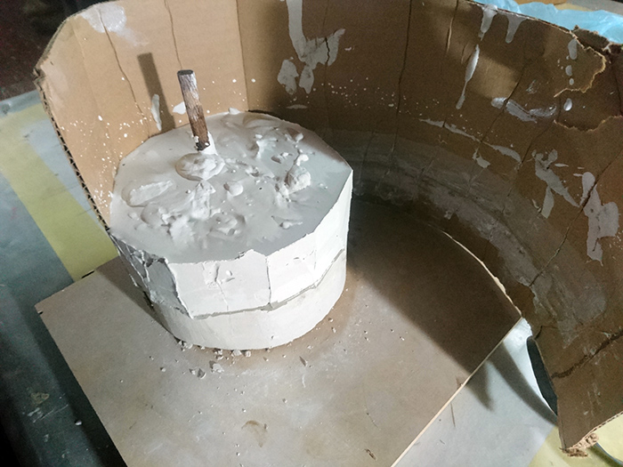
In the process to make the mold first mark the middle of the piece and with ceramic clay make the base of the mold, for the base in ceramic clay make circle with 3 cm more of the piece, then remove the excess of the ceramic clay.


Now, from the uncovered side of the mold we anoint release agent so that the plaster does not stick, then surround it with cardboard and we cover the holes with more ceramic clay, mix plaster with water, plaster 60% and 40% water, and immediately put inside the mold, shake it little so that the bubbles come out, wait for it to dry, remove the cardboard and the ceramic clay.


To the other part, first mark the position of the mold, the mold makes the same process and add something where the liquid enters the mold and open it.


I use paraffin to fill the mold, pour it slowly so that it does not create a bubble inside the mold, wait an hour until it becomes hard and remove it from the mold, by a bubble in the mold the lamp broke and another was created by filling and not filling completely.


In this assignment to molding and casting I will do a lamp, first to begin I use solidworks to make a design for lamp, my design is very simple but the objective is take the translucent of the rubber to illuminate.
In solidworks, I draw a plane contour firs then extrude at de measure desired, contour have a thickness of 2 mm for the printer 3D, this measure change until to avoid wasting material when printing, is design for a lamp to study, was added a space for the battery.


To my mold, I use a printing 3D to make a mold and taste with silicone mold, in the preparation to pour the material, first seal in the base with hot silicon and the definition of print is not good, seal some holes, the mixing percentage recommended for maker is 100% silicon and 100% catalyst, but in the test, is better use a 100% silicon and 25% catalyst because the reaction is slower and you can work best and more time to move for remove the bubbles.


After pouring the material, the mold had a leak to print quality, for place LED strip into the lamp paste a toothpick to give it firmness, in the moment to pour the silicone in the mold, sink the LED strip and adjust with hot silicon to dry it, lasted all night to dry, in the next day to try extract of mold, by the thin of mold, it broke and reduced height, for finish with a voltage generator taste the functioning of the lamp.
For the milling make an experimentation with plaster and how And how do you react it you can see in the beginning of this assignment.
For the design for the mold I use a solidworks for make the piece to create the mold, the construction for is simple is made in 3D printer, for the liquid that I use silicon for make the casting and this the process you can find in the middle of the page.
For the files use a parametric design and simple design in 2D to extrude it, the design is for can to enlarge at de measure of the user wants or depending on the height of the machine, a recommendation is for the mold width because all the silicon trespass the wall I made, the design part of a rectangle and with the tool rounding the form is given.
For cast the lamp remember before filling fill the mold with a release agent so that the silicone does not adhere to the walls of the mold and is easier to remove, the process is explained in the process of the first objective.
The problem with the mold is the width because allows the passage of silicon through it, use a correct release agent because the silicon is adhesive.
Files in Repo