SolidWorks
In this week, I used the program solid works to make a render at approximated design of the machine to build, this program make a very complex design,
you can simulate Its functioning, solid works allow us export a different format for later work whit a machine.
Whit this simulation we can know if the design requires corrections and see the correct functioning.
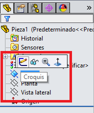
To initiate for make any design, solid works allows us work in plane, first we choose in plane to make a work to start the design and select whit a click and
press in the first image "croquis", next select the figure or line to edit and make a design, to give a measure you have click in a line and in the specifications,
you can change the length and another measure, when you decide finish the edition press in leave the sketch.
The next step we will extrude the figure, to be able to perform this step we must be sure to leave the sketch and in the toolbar, press in operations you have
all the tools to edit 3D any design also has to make extrude cut, once the extrusion has been made, if you wish make an extrude press in the bottom, then you can
modify the value of the extruder in the options that appear.
To perform extrude cut you can work in the plane of the figure made, with a click in the plane to work and select sketch, you can edit all you need to make an
extrude cut, is a similar prosses previously, then to finish edit leave the sketch and go an operations whit a difference select a tool extrude cut and edit whit
the same prosses as before, in the options change the depth cut.
When finish all the pieces, make sure to work on different files each pieces, you must have a method of anchorage or assembly, taking these steps into account
proceed to an open a new file and choose assembly, a blank solid works window will be displayed and you can export all the pieces for assembly, when you export the
piece you can turn in the axes x, y and z, to adjust in the correct position, with the tool Position ratio you can assembly the pieces with method that you have done,
you select the ranges to fit well, if you choose the correct limits the pieces they will join and repeat this with the others pieces.
Solidworks
In this assignment I used this software for make the the figure, for this design first create a comb to have the right measure, then make the design
in Solidworks is easy interface, you must take into account the measures in which you are making the drawings.
To star first make a sketch of the design with measures and details, and when start the program solidworks work first in 2D, make sure to measures is right consider thickness of
the material, for a correct press fit. then continue with the software seeing if the units are correct before you begin to draw so that you coincide with the size of the sketch.


Before you start drawing we must know some essential commands to draw in Solidworks. Select the correct area of you need work, in 2D you select sketch in the area you decided to
work, this sketch you must click in the area and select the icon with a pencil.
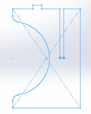
based in sketches, drawing with the commands seen using the tool center rectangle to make a square fast with the measures annotated, make a circles of radius 300 mm in the middle
of the line, using the tools sketch rounding and trim entities, remove the excess line and sketch rounding rounded the corners, finally make a coupling to fit the pieces of 32 mm.
In the second design also based in sketches, first make measures of the top line of the sketches with the tool center rectangle make a square and the couplings in the space of 31
this measure is different of sketches because corrected at dimension of material, dog bone in the couplings for So that the feet can be adjusted completely, and we repeat the previous
process make a circle of 300 mm of radius and complement with tools sketch rounding and trim entities to finish the design.
In the last piece make a rectangle for the table, to situate rectangle since the middle of the lateral line measure of 134 in horizontal and 165 in vertical to point to make
rectangle, to second rectangle, take de same measure in horizontal 134 and add 171 for make the rectangle starting from the middle and use the tool symmetry of entities to complete
in all de design.
advantages and disadvantages
this software is very complete and have many tools for make the design, you can make assemblies, simulations and for all this process some operations can be complex if you do not have the necessary knowledge of the software but if you like this, It will be very helpful, it is good that the software works in parametric design or with type of restrictions that you can give the sketch, the software needs to perform many processes therefore it is heavy to be able to work in any computer and you need to pay it in order to acquire it.
2D software
Autocad
Autocad
In this assignment, I test this software for make the same figure that I did in the previous software, then make the design in Autocad, you must take into
account the measures in which you are making the drawings also with the previous software, when finalizing grouping the lines to handle more easily in the software Inkscapethis,
software is very simple of use but not is parametric design.
advantages and disadvantages
Is a very simple to use software, the commands is not complex but the software not work in parametric design but you can convert it with a tool, If you do not use the tools correctly, the program may not be accurate when making the drawings, but you can correct the error easily, you should be cautious in these cases, the software is paid but if you are a student you can get the licenses.
Fusion
This is the most important part of the software in the moment to make the design.
For the base of the design use a circle in a first sketch and extrude it, next in top face create another sketch and apply the same process to create the figure.
In the top disc use the tool extrude to make a little cut and be able to make a sketch and use the same tool and create like a box.
The previous step is the base to this process, make more sketch and use these tools to create the figures, circle, press first in sketch, and rectangle next to give color or texture to the figures use appearance in modify.
In the last step use create sketch, circle and extrude to create the piece and in this case use also the tool appearance to give you a view of glass.
advantages and disadvantages
Is a very good software of 2D and 3D, is very similar to solidworks you can make assemblies and simulation to the design, if you work previously in solidworks this software is similar with some variations, In my opinion fusion is more didactic than solidworks and you can guide yourself with online tutorials on your website, the software is free and some process the software make on your servers and not in your computer, you can make process for the machine like a mill and others but all this process is complex to understand.
- Demonstrate and describe processes used in modelling with 2D and 3D software
For this process, I did screenshots and a tracing of the design and who made this process and explain some tools all this documentation you can see in the first objective of this page.
have I:
- Modelled experimental objects/part of a possible project in 2D and 3D software
For the model in 2D and 3D use SolidWorks because this software work in the two models, the example is described in the top of the page.
- Shown how you did it with words/images/screenshots
All the images and screenshots you find in the two objective in the top of the page.
- Included your original design files
Dwonload files
FIles in Repo.