Computer Controller Cutting
Laser Cutting
- Make lasercutter test part(s), varying slot dimensions using parametric functions, testing your laser kerf and cutting settings
Group Assignment
In the group assignment the objective is know who the laser cutting works and what parameters you need.
We make a comb to test the measure of the presfit in an MDF wood, each space has a different measure to try with the width of the wood of 3mm.
To make the file in fusion 360, first you need create a sketch and occupy the tool rectangle.
The figure uses the tool with two different sizes and save to dxf.
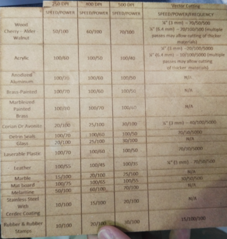
In the image show the parameters to use the machine with the different materials.
In the image, the parameters of the machine of the material to be cut are placed, in horizontal and vertical is the total size of the material, next put the parameters shown in the previous image: speed, power, and frequency.
In the buttons of the machine use number 3 and 4 to setting the axis z, once adjusted press start button to start cutting.
Presfit Kit
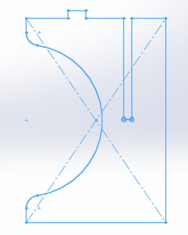
For the presfit kit I use the software solidworks and to make the skethc in a 2d design use the polygon to create a triangle, next in the middle of all the sides of the triangle make a square have the necessary presfit measurements, next in the center make a circle and tickets will be made for squares made previously.
Next extrude the two pieces and save it in two different files, this is for make the next process which is an assembly of the pieces.
In the assembly you must open a new file and select assembly, then load each file that appear in the right side, next with the restrictions you can select the part of the figure who wants to get together, in this moment It can be seen that the tips of the triangle collide therefore rounded the tips to avoid it.
Next in the software go a technical sheet and put here the design and once this is done export the file to .ai of illustrator and save it.
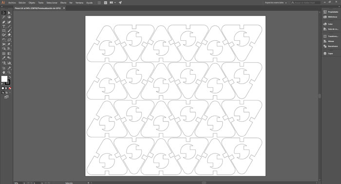
Finally, in the software of illustrator edit the design to optimize the area of laser cut and to configurate the machine you can see the other taste.
vinylcutter design
To make this file use the software adobe illustrator, illustrator work with vectors and appropriate for this part, first with the tool pen, with this tool make the contour of the figure giving points.
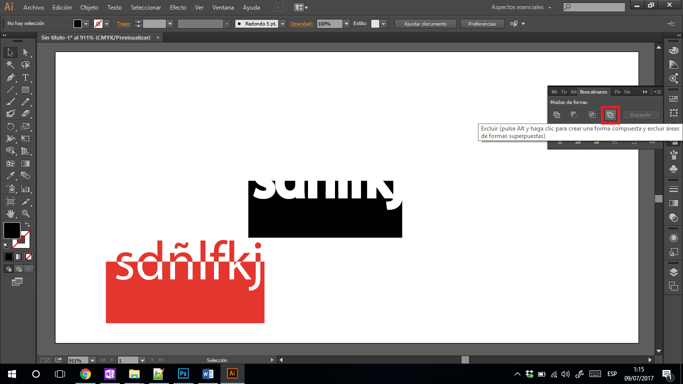
For the next tool, in the working plane, give right click and select the option buscatrazos and it will appear a window and select the last button exclude to give the letters a contrast effect.
And this method uses in the design and finally in the letters make use the option create contours, this tool is used to convert the letters to vectors and be able to work better.
Individual assignment
To make the design we will use the software Fusion 360 with the tool create form in the start tool bar.
To begin press in create and select the sphere, next in the window that will appear select the parameters of sphere first select diameter what do you prefer, and in longitude faces and latitude faces you select the number of divisions of figure will have and press ok to insert.
To edit the figure, use the tool edit form in the toolbar to begin to make the design.
For use the tool first select de lines or faces to be modify, next press the tool and with the select the different parameters in the window or use the arrows in the figure you can specify the measure to edit or move the arrows whatever you need.
Different objects can be obtained according to the modifications made in the figure.
The next process need download the complement to fusion 360, slicer, you can find this complement in the page of Autodesk or in this >>link<<.
To work first import the file direct to fusion or you can save in format stl and open it, to import you can press the button import and select the file.
Next you can edit the size and characteristics of material, you can select the unit of measurement, first press in the pencil button and select the characteristics of the material, if you cannot find the right one, you can create one press in the plus button and you can configurate all these parameters, if you want a great tutorial of who use this program go in this >>link<<.
The next parameters are chance change from inches to millimeters, next press in original size to work with measurements that you created the file, then select the technique of make the file in my case I use interlocked Sliced.
With the button slice direction change the direction of the divisions if you want, and the final press in get plans and you can decide the format and if you save in your computer or export fusion 360.
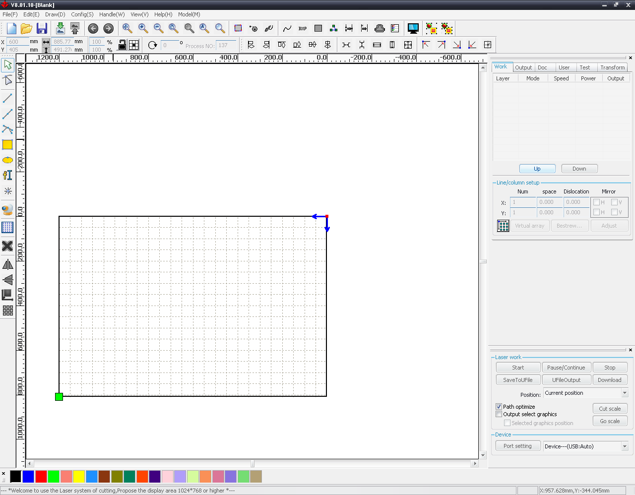
The software to use in the machine called RDworks is for edit all the parameters of the file.
Next, import the file, for this machine it is recommended that the file is .ai illustrator type, then select and open it.
Once the file has been imported, the square green moves and give the zero point that the machine must start, in the right part you can see the colors of the lines this show you the configurated of each one.
You give double click in the parameters of the lines, appear a window where you can modify all the parameter of each line, in output you select if the line makes or not in the laser cut, next you can select the process if it is recorded or cut, next you can chance the power of laser this if it is recorded or cut.
Next in in this part you can send the file to the machine or only send the code to the machine make the file, to begin the cut can press in start or if you send the file press in download.
With arrows you can move the head to set in the zero point, and for save the point press in the button origin, then press in file and select the archive and press start button and begin.
To set the axis z, need use this piece you can put under the head and this is the height that needs the head to function.
Head in the position, in the origin point to start the cut.
You can control the cut and the progress of the file in the screen of the machine and the time.
process of assembling the pieces after the laser cut, remember to make a fair measure the space in which the pieces will be made the presfit to avoid difficulties.
First test
In this assignment I used this software for make the the figure, for this design first create a comb to have the right measure, then make the design
in Solidworks is easy interface, you must take into account the measures in which you are making the drawings.
With this first laser cut find the correct measures for a good presfit, this taste is for the other design for know how much the laser wears on this type of wood also to what
kind of power is working with the laser.
To star first make a sketch of the design with measures and details, and when start the program solidworks work first in 2D, make sure to measures is right consider thickness of
the material, for a correct press fit. then continue with the software seeing if the units are correct before you begin to draw so that you coincide with the size of the sketch.


Before you start drawing we must know some essential commands to draw in Solidworks. Select the correct area of you need work, in 2D you select sketch in the area you decided to
work, this sketch you must click in the area and select the icon with a pencil.
based in sketches, drawing with the commands seen using the tool center rectangle to make a square fast with the measures annotated, make a circles of radius 300 mm in the middle
of the line, using the tools sketch rounding and trim entities, remove the excess line and sketch rounding rounded the corners, finally make a coupling to fit the pieces of 32 mm.
In the second design also based in sketches, first make measures of the top line of the sketches with the tool center rectangle make a square and the couplings in the space of 31
this measure is different of sketches because corrected at dimension of material, dog bone in the couplings for So that the feet can be adjusted completely, and we repeat the previous
process make a circle of 300 mm of radius and complement with tools sketch rounding and trim entities to finish the design.
In the last piece make a rectangle for the table, to situate rectangle since the middle of the lateral line measure of 134 in horizontal and 165 in vertical to point to make
rectangle, to second rectangle, take de same measure in horizontal 134 and add 171 for make the rectangle starting from the middle and use the tool symmetry of entities to complete
in all de design.
All this symbol notifies work with restrictions, with respect to another line, if you removes this restriction you don’t work in a parametric design, these restrictions are linked to each other because if you modify one the others change the measure respect to the modified line.
Already finished design export to the fotmat dxf, So that the software recognizes it and can edit and adjust it, first change the size of the dimension
the size of the iron to be used, situate the design anywhere and change the cut line at 0.025 and adjust the recorded if necesary, finally export a format
PDF to cut.
Open the file in pdf and click in print and select the machine to use, in this window change the parameter, change the speed, power and freq of vector setting in 30, 70 and 1500
respectively, don’t forget change piece size at size of your material, then for setting the machine you need use only two buttons for adjust the bed of work and once make this
press start to cut the design.
fusion 360
For test the other software I use Fusion 360, this software is similar at solidworks, I make the same design to compare with another program and see the difference, this
software is free and you can download in the page of Autodesk, Fusion is like AutoCAD because have the same commands but with more specifications and complete because this
software is for work more in 3D.
To start with the design, first press sketch and next select the plane to work, then with the command rectangle make a square of the measures, you can give it a specific
measurement only write de number of measure and next with the key “TAB” for give the second measure. The tree design has the same beginning with the command rectangle.
Then with the measures make the others parts of the design, for the others parts I use commands line, trim, circle, filet and mirror, all these commands are in the toolbar
in sketch.
In the software fusion 360, the files save in a cloud but if you need download the file first go at file and click in export, next you select the ubication and download the
file.
Learning outcomes
- Demonstrate and describe parametric 2D modelling processes
This demonstration is in the third objective of the page, I use solidworks this software uses parametric design and for this assignment I occupy and describe the design in this
program.
- Identify and explain processes involved in using the laser cutter.
The process is not complicated for complement and edit the design if you need you can use Inkscape, remember for use the machine probably you need an extractor for the smoke and
all that produce the laser cut machine.
Develop, evaluate and construct the final prototype
For the test with the first laser cut, the presfit is very good and the pieces fit well, a recommendation first make sure of the measures before of cut this is for no problem
with a presfit or tatting in others measures, remember make a sketch with all the measures for no complicate at moment of make the CAD.
Have I:
- Explained how you parametrically designed your files
For the parametric design use solidworks and you can see the process, up in the page.
- Shown how you made your press-fit kit
For your presfit teste I recommended measure the width of the material and give higher and lower values for test and get a correct presfit of the material that you use, recommended
if you work with millimeters increase by one millimeter the biggest and smallest measures.
Vinyl Cutting
stickers
For the vinyl cutting use a stickers in a cameo machine, you can see the vinyl cut in the second objective.
- Identify and explain processes involved in using this machine.
The first step to occupy the machine, first need calibrate the height of the blade, this depend of the archive or for you need occupy, the point red indicates blade level,
this calibrate is for the depth of the blade relative to the paper, next step press in load cutting mat and collocate the paper or adhesive in the mark and in the end of the
preparation of the machine press “load medium” and the paper enter in the cutter, and finally in the software press cut and the machine begin the cut.
- Design and create the final object.
For the design is very simple, the design is made in the software illustrator, the first step to make the design is use the tool feather or pen, with this tool make two
triangles and one half circle and one triangle of another color, then add text, when the text and design is in the correct position select all and right click and press in
create contours, done this step go at window and click in searchers and in the box that appears select the four option for create the effect in the letters and in the design.
have I
- Explained how you drew your files.
For drew the file use the software illustrator and cut a simple but great design and the simple process you can see in overhead of this point.
- Shown how you made your vinyl project.
This process you can found in the second objective of laser cut and in vinyl cutting.
- Included your design files and photos of your finished project
Dwonload files
Files in Repo