


For the test of your machine and you know the how it works and the reaction in the different measures.

For the test of your machine and you know the how it works and the reaction in the different measures.

To change the format use fabmodules, first select the image, next select format to import in this case .SVG and select in outline, then change the parameters like a tool diameter I recommend use to 0.01 to make all the line and select offsets in 1 and finally press calculate and save.


1.Case. - I use a broken mill and zero point it’s wrong because in the moment to set the machine the mill did not sink sufficiently and did not remove the copper.
2.Case. - I corrected the z point but is the same mill.
3.Case. - I change the mill but the bed is badly leveled.
4.Case. - I make with a good mill and better bed calibration.

The mill is an angle of 10° degrees and the precision of 0.1 mm.


when get the image of the circuit, open with fabmodules and set the parameters: output format in roland mil, size of drill 1/64 for traces and 1/32 for cut. next choose the machine whit which we are going to work in, Try zhome, yhome, xhome at 0 to finish the machine process and return to the starting point but were not those parameters and change for x0, y0 and z0, finally look at all the parameters that are correct and select calculate from get the file you are going to work on the machine.


before starting be sure you have the correct mill 1/64(traces) or 1/32 (cut) and be sure that plaque fixed to the base of the machine. Once secured, we begin the configuration of the machine starting with placing the starting point of the machine in X and Y(x=0, y=0) and setting z with the sensor that is conected because can damage the sensor, before to start cutting, verify all the parameters be correct and press "cut" to proceed cut.


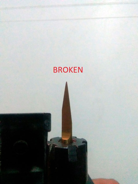
when cutting, don't interrupt the proces if the cut is correct but if you see any problem stop and configuring the machine again, If the machine has any error be be careful with the mill bcause the machine loose the base of mill and can break.
With the group we cut all plaque in a single image, but the problem is the space between the plaques is small for the machine when make the cutting, Consider the space between them to do this way, in this case just broke the outline and continue with the next process.
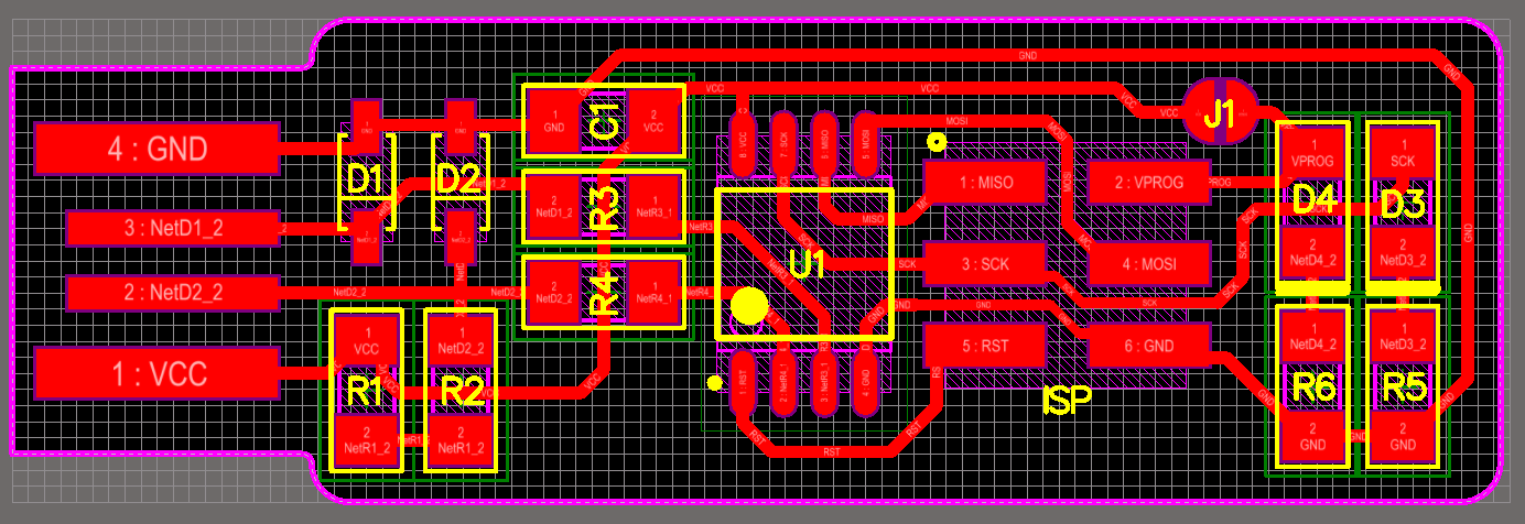


Before starting to solder the electronic components you must know which are going to be used and where is the position of each one, all this information you can find in the schematic image, the picture includes the name of the traces and the position of the microprocessor and some others components.
Be careful with not to overheat some components as they may be burnt by the excess heat emitted, Not use too much tin because it can join the tracks and make a short circuit, Use a little solder paste to do a better job.
For make a programmer use another process and make the fabTinyISP, this is an improved programmer and the process is in the first objective, if you need more information go at this >>link<<.


For more information of the microprocessor you can see the datasheet in this >>LINK<<
I used a usbtiny for programed the new plaque, First download the FIRMWARE
to need for progrmed, or all the information of the plaque
HERE
To conect the plaques you must know the ground (GND) of the headers and you computer recognize the USBtiny you can see in device administrator


to program first open the firmware and edit the makefile, in the make file read all the indications of "make" and explain your operation, in the makefile view the next specifications: the microprocessor and your fuses, in the next pass if you have windows 7 no problem but windows you need this program
CYGWIN
First, copy the direction of the folder and the first step do a make fuses to creat all the fuses in the microprocessor and to up the program you have a make flash and wait for a message fuses OK, and see to create files in the folder of the firmware to correct.
For the milling, be careful with the mill because if you work with the different parameters or other mill the size of the traces varies, if is necessary you can make a first taste in the air for not damage the mill and see is all is right.
For programming is a little higher than this question.
All the process and errors you can see in the first objective of assignment and precautions too.
This you can find in the finally of the all the process to make a programmer.
Traces
Cutting
Test