3D Scanning and printing
- Test the design rules for your printer(s) (group project)
Printing 3D
I'm using the software to make the solid to print , solidworks is very complete from design and simulatuion, solidworks elaborated design in 2D and 3D, first drawing the
solid in 2D and then extrude to pass of 2D to 3D, the interface is very simple to use.
First, before to drawing we should know in that plane we want to work x,y; x,z y,z or other. In my case first I use the plane y,z; first drawing in 2, with the tool
rectangle make a square of 70 x 70 and extrude 5 mm.
In the next step I made two triangles of the same size and three circles of different size to know the reduction of the measure, for the triangles I made a rounding
in one and chamfer in other to see the difference of how work the machine.
In this step I use the command “Rounding” to eliminate the beaks in the corners and for the machine not lift the piece.
In this part I make a small square around of the circles and the triangles with the command “extrude”.
Now to practice I make a star to practice the software and to see how it function the machine the star is made with two equal triangles and the next
step use the command “extrude” to generate the figure.
Finally, I made a figure like a worm is a little difficult to make in the software and to see in the machine first, use a half a circle to make the curve and
next with the command “equidistance” to make the width of the line, join the two lines to occupy the command “extrude” and finally with command “rounding” to curve all the figure.
When we already have the solid solidworks also can work in 2D to transform
3D, which was the next step, either do. I continue with drawing the star to differentiate how works with the next figure, since the star is straight and the another is round.
Before to print, first, chance the format of the file for the machine recognizes, also chance to the best position to print, depending on the machine is going to be a different
format, I try with two different machines.
In two software I had flip the figure to make printing easier, In the program I did not have problems but the second machine I didn't see that the figure is not horizontal.
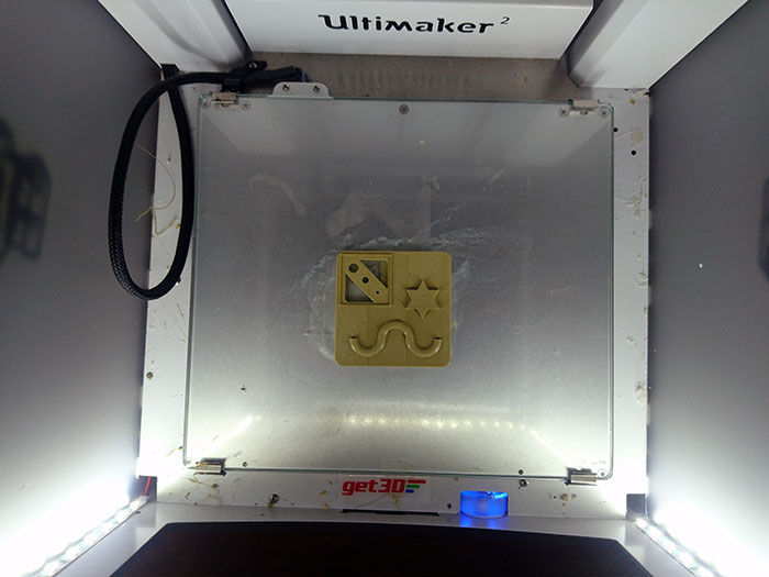
To print the figure is very simple first export the file at memory card and place it in the slot then in the screen you can see print and with knob use to select “print” and
turning it to select the correct file and finally press the knob to print the piece.
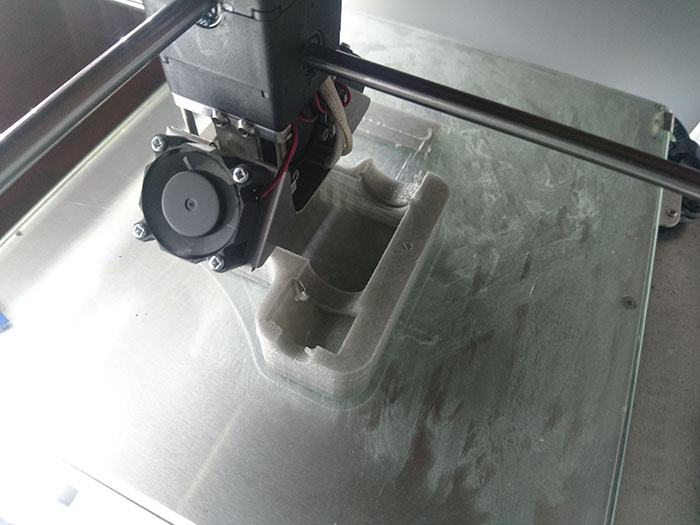
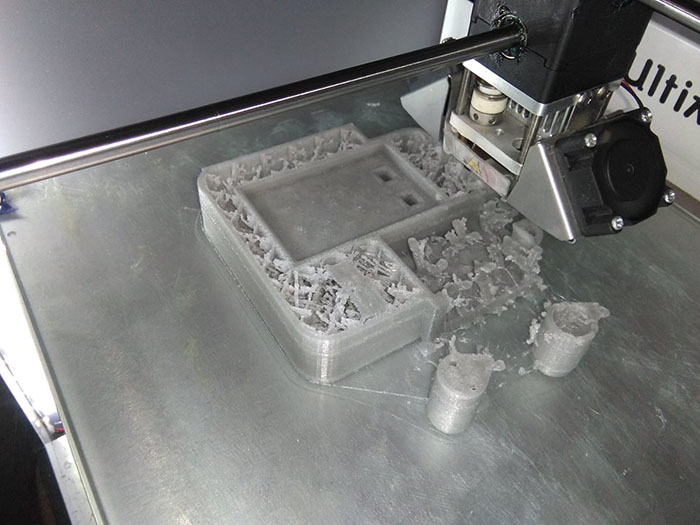
the two machines works different and have distinct sistem, the first printer use rafts and the another print direct the object, but the second printer had a inconvenient
the solid was not completely horizontal printed a little in the base of the printer.
the first printer move the base of the solid and fail the printing, the second printer continue with good printing
the printer finish the process, the printing during around a one hour, during this time were no problems with the printer, the filament is biodegradable
To remove the figure you can see the error, it's not big but has a very details where you can verify, the lines that are shown are of the inclination that occurred
in the software for adjusting correctly
- Design and 3D print an object (small, few cm) that could not be made subtractively
To the design, I occupy the software fusion 360, first create a sketch, 1. With the tool rectangle we make the basis of the design, 2. Use the arc to curve a side of the rectangle, give three to insert the arc in the sketch, 3. Use offset to make a parallel line, the distance of the line is 2mm, then with tool trim delete all the excesses, 4. Use line to make the triangles, be sure that the angle of the base of the triangles is 45 degrees, this is for the impression not use support, finally 5. Circle option tangent to make inside of triangle.
Now in the area of the two parallel lines select and use the option revolve to respect a front line as axis of rotation.
With the triangle and the tool extrude make a hole in the body, select all the area of a one triangle and drag the arrow until cut the body.
Occupy the tool pattern and select the option circular pattern then select the faces of the triangle and select the same axis that in the step of the revolve.
And repeat the last process for the circle above and below, and for the triangle below.
Next in the software cura to create the gcode file but first configurate the different parameters of the printer, printing temperature in 230 and 70 degrees the build plate, slow down to 40 mm/s, and disactivate the cooling, I recommend the build plate adhesion select brim.
And finally, to upload at the machine select project manager next press in add files and then in print.
3D printing
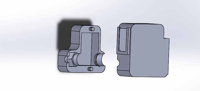
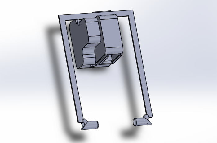
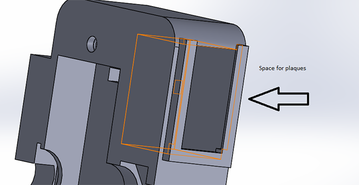
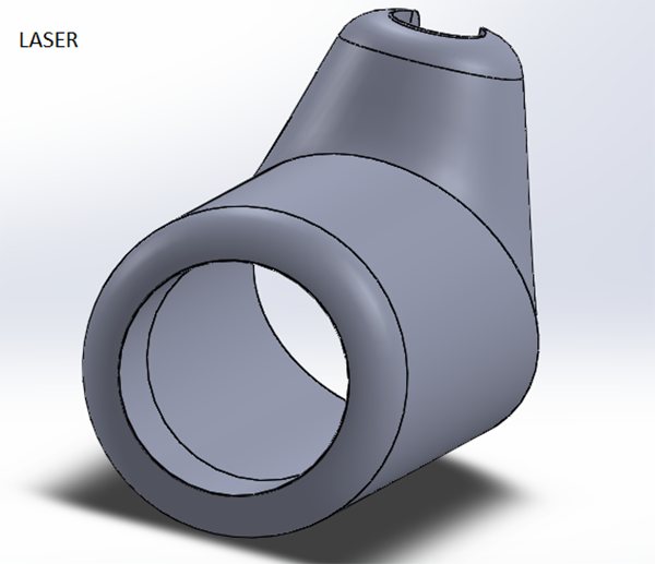
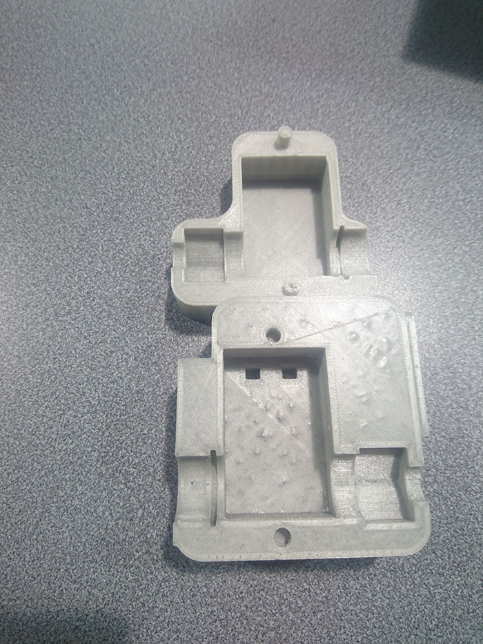
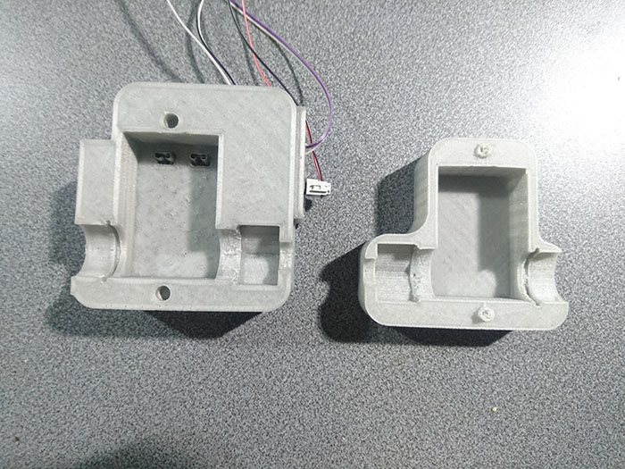
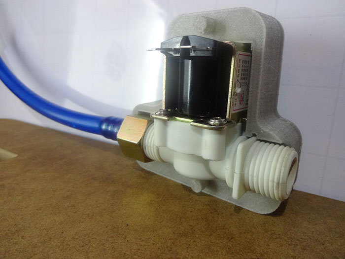
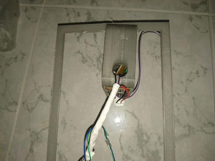
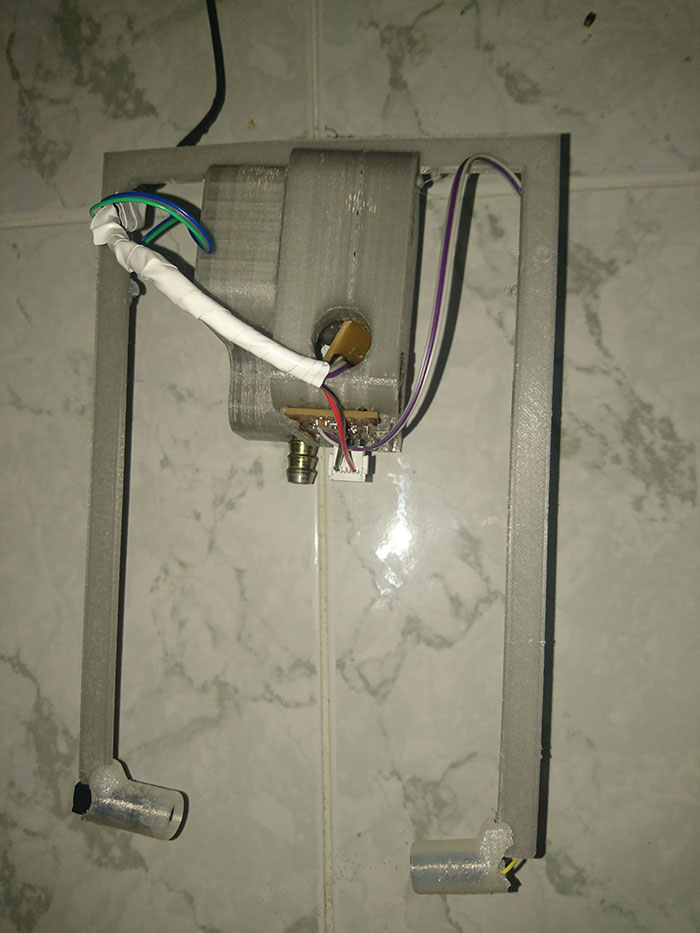
In the design, I use solidworks for make all the extrude, the design for the electro valve have space for the connection the valve and a space for the plaques of the project,
for the design make sure for the measurements of the valve because in 3D printing the piece have a reduction and you need an excess.
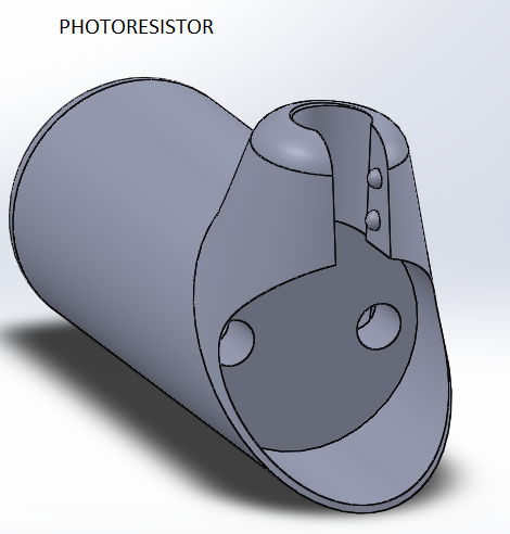
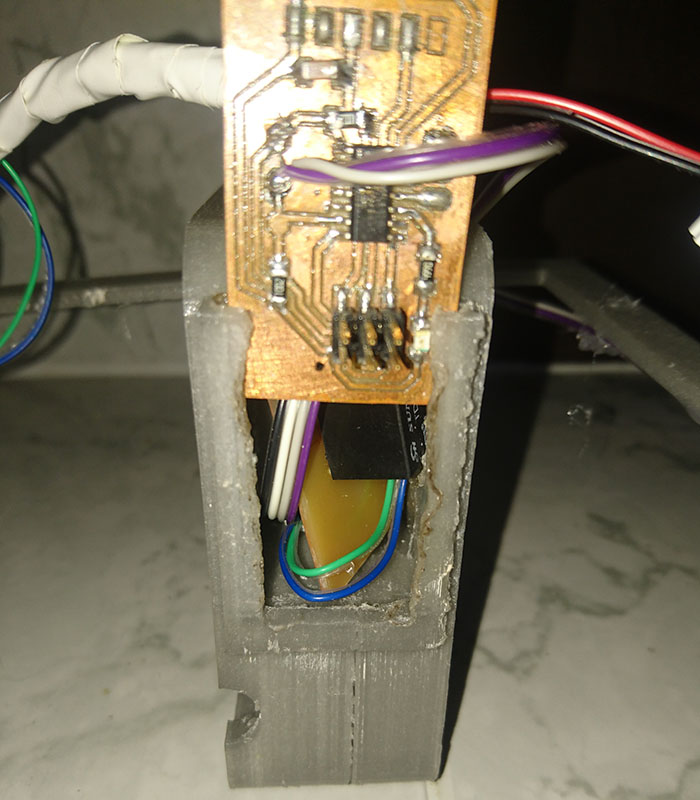
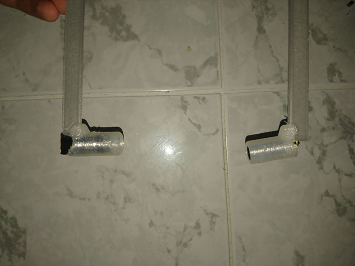
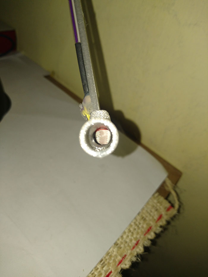
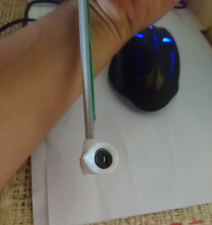
For the photoresistor and laser made a case, in the photoresistor for the external light do not affect in the moment to react at laser and when the laser is block for the
liquid ceramic.
- 3D scan an object (and optionally print it).
3D Scanning
To begin with the 3d scan we use the microsoft Kinect sensor and to complement the scan with the software Skanect where we will realize the whole process of the
scan in 3d, When starting the software and start a new file and clic start.


To Star scanning we must see that the person is a correct distance, the distancie is see in software, on the bigger screen your body should be in green so the sacan is
correct, At the time of scanning must be slow and seeing that in the program that the scan has no holes, we help of a bank to rotate on the axis, then raise up the kinect to
scan the top of the head and avoid the hole there, finally press the button red to stop the scanning and wait to build the figure.
Learning outcomes:
- Identify the advantages and limitations of 3D printing and scanning technology
The 3D printer is a good technology but only like get a prototype, because for the type of material with work, the time can be a advantages and limitations because e for design
that you can make a 2D design with laser cut the 3D printing is very slow, but can realize designs with a certain degree of complexity, a limitations when the extrude have a problem
and damage all the printing and make again, the 3D printing is a good tool to make prototype but this have a limit, if you know the system and you can handle it well it will be of great
help.
- Apply design methods and production processes to show your understanding.
The methods and the process, how make is in the top of the page and more details, this description is in the taste of the machine with the first design.
Have I
- Described what you learned by testing the 3D printers
I learned that all the printers work in different ways and at least a test to know the parameters and if it is necessary to correct the file or to adjust the machine, be aware
of the printer as it may be inconvenient and damage the print, adjust the parameters between one print and another can generate variations in the measures.
- Shown how you designed and made your object and explained why it could not be made subtractively
You can see the design in the second objective and all the process how make and build it.
Scanned an object
The scanner uses a Kinect to recognize the body and a skanect to software for complement the scan the body.
- Outlined problems and how you fixed them
the problems are present with the design not finish to complete and you need print it, this problem you can fixed in the software or with support, another problem is not adjust good at bed to print.
Included your design files and ‘hero shot’ photos of the scan and the final object
You can see this in the two first objective and next the files.
Dwonload files
Files in Repo