This project was inspired by Wilhelm "Willi" Ubelherr, a German cyber-activist. He designs technological systems for the construction of local autonomous communities. It was devised with the great ideas of my friends from FabLab Zoi: Roberto, Alex, Juan Felipe and Fabio.
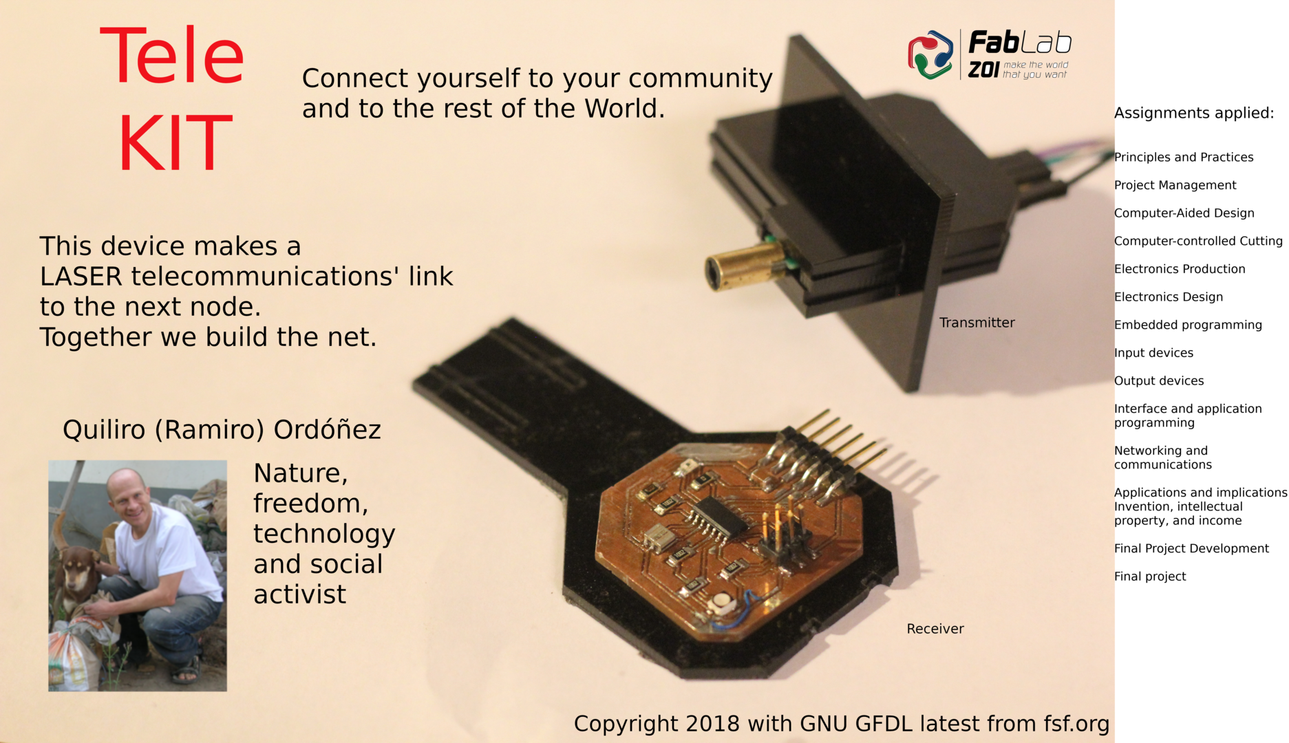
My final project is TeleKIT. It is a telecommunications device that works with line of sight visible light communication. It will be possible to have a kit by building the pre-made parts or by constructing them yourself. In my FabAcademy final project I need to construct a device that (primitively at least) is able to work to send and receive data with light with no other media than free space.
Autonomous communities produce and consume locally. That is only possible within a modern society through unbarred exchange of knowledge. Telecommunications are the best way to do it massively. But they must be libre (free as in freedom) in order for the community independent in practice. The construction of this telecommunications device is a first step towards that objective.
So my project is to construct a device which links nearby or distant places by way of line of sight light rays for data communication. It is the essential element to make a network where each node will link by way of light rays with others. It should be a peer to peer network. WiFi or LiFi will provide the local network computers and cell phones with a remote data link to the rest of the World.
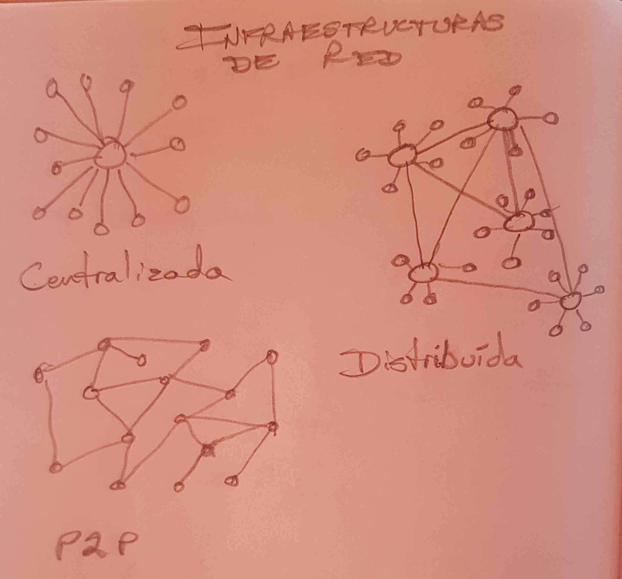
Communities need a telecommunications device in order to transmit and receive knowledge between themselves and convert it into life in plenitude (Sumak kawsay) and without the need of corporations. TeleKIT is a project to transmit bits and use local atoms instead of transporting products. We will use it for interconnecting without providers (as a mesh) in the style of Guifi.net or Buenos Aires Libre. The Internet is the intercommunication of local networks. In order to be free, we must create and intercommunicate our networks codependently. Lets do it!


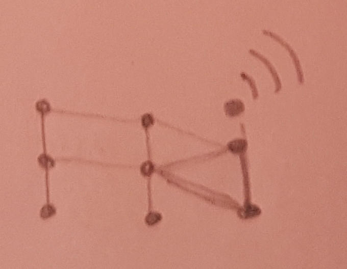
Perhaps we could use just 3 links. But 4 links is better.
Light communication can extend long distances by way of several jumps. It can be redundant by different links to each node. That can also make it parallel, which provides more bandwidth.
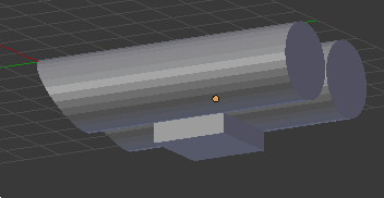
TeleKIT works with convex lenses or with parabolic mirrors. The light rays become coherent (parallel) with this system and does not loose its intensity by dispersion.

Light communication does not have the problem of Fresnel zone interference (light has 10 mm Fresnel zone) or crowded bandwidth (it is point to point, line of sight communication).
The telecommunication's device could have 4 sets of double or single tubes similar structure as:
It is possible to have long links (1.4 kilometers) with only one jump as demonstrated by
RONJA.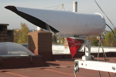
TeleKIT is a project to implement, improve and simplify massive production of RONJA.
Some experimenting with a simple LiFi telecommunication device done with Arduino was suggested by Isaac, my remote guru.
RONJA is a masterpiece of design according to experts that have analyzed the project in depth. It is an honor to construct it. Here I describe the steps I have taken to make 2 working prototypes.
RONJA website has plenty of information about construction, has an active mailing list and a lively chatroom. All documentation regarding the parts, diagrams and bill of materials is provided. Even part numbers for 2 suppliers are specified. Nevertheless, certain electronic parts are no longer available for purchase. And the part numbers are previous references that are not used any more in that supplier. The other parts are easily found except for the loupes (magnifying glass).
My current mission is to have a compiled Bill of Materials for the 3 necessary electronic components: transmitter, receiver and Ethernet interface (modulator). These CSV files are also available as HTML files on the RONJA website. I made a compilation of these three files for making only one order of electronic parts. But then I found the augmented list. I am now making a new bill of materials by finding the available replacements for discontinued parts and by changing the old part numbers with the new part numbers.
I have not progressed with my experiments on Arduino LiFi. I have learned a lot about Arduino. But I have not understood enough to make the suggested tests.
Probably now I can make the tests with my own input device and output device boards. They both have a photo-transistor. The input device lesson board has a white LED and the output device lesson board has an RGB LED. I think I can use it to transmit 3 bits in parallel.
I have not progressed either with RONJA parts search. I have decided to build just a simple point to point light communications project with the least possible attainability for me. RONJA is too complicated to learn from zero knowledge in just one run of FabAcademy.
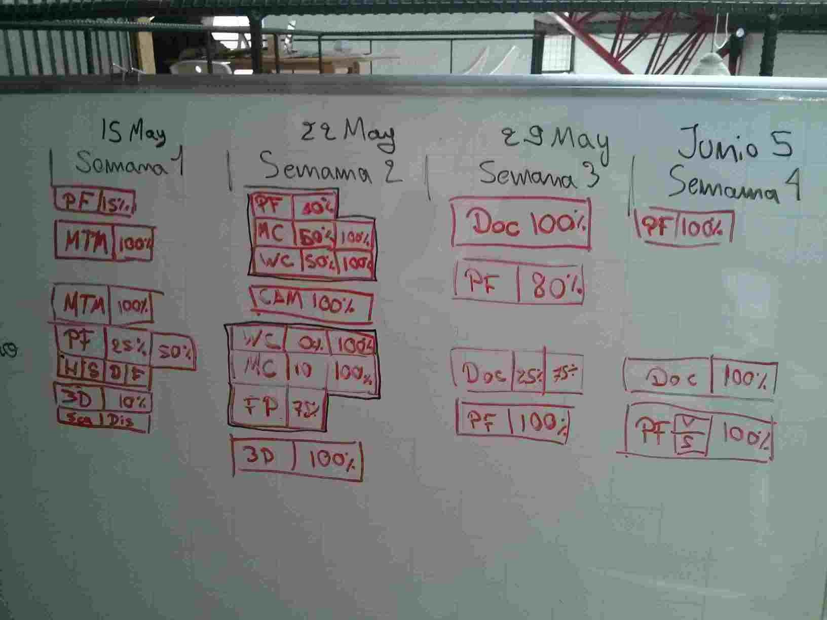
My instructor and I have constructed a schedule designed to combine FabAcademy lessons with my final project milestones in order to make better use of my time. It is detailed on a readable table at the Principles and Practices page.
Motivation is paramount for productivity, I have taken a photo with a graffiti that motivates me based on the future reproductibility of TeleKIT. It transmits the message to me that people throughout the World who read the manual of how to construct TeleKIT, will build the device and the free network. This motivates me to document the process on the go.
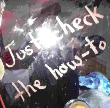
If you want a to become part of the libre network, just check the how-to in order to make your part!
Even though I have caught up with the documentation, advanced with the assignments and documented on-the-go, I have not been able to keep up with the programmed schedule. Currently, I have decided to integrate the assignments to my final project process:
Anyways, I do not think I will be able to conclude 3D printing (even though I have a design that cannot be made subtractively) unless I design a box for the final project.
I have made another reschedule as detailed at the new work schedule section on the project development page.
I could blink the LED of one board by detecting the light of the other board LED when it blinked.
I could make an animated GIF of different size images. In the first place, change the images to the same width and height without stretching them in either way.
mogrify -resize 640x480 -gravity center -extent 640x480 *.jpg
Then animate these images into a GIF image (set a 1 second interval between them).
convert -delay 100 -loop 0 *.jpg output.gif
I could transmit with one device and detect that transmission with the other device.
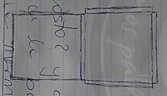
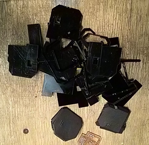
I have manually made a case with cardboard. I made a folding piece. I think it looks great. It was time to computer design the package. So I started with FreeCAD. Nevertheless, I could not even copy the shape of the SVG image of either of the boards' cuts. So I decided to follow the tutorials I had downloaded. I made a detailed plan of how to make my boxes:
I found I was not prepared for doing this in FreeCAD in such a short time-frame. I tried with Inkscape. Even though it is not designed for engineering, I could use it to design and cut the pieces. I made a model in sketch first.
This is the process for design and construction of the receiver casing. It went through several designs.
A lot of tests for press-fitting.
And this is the process for the design and constructions of the transmitter casing.
It is time to make my slide and my video. My slide has:
convert original_file.png -resize 1920x1080 presentation.png
The video was reduced to less than 8 MB with:
ffmpeg -i original_file.mp4 -b 8000000 presentation.mp4
I could show the packaged project transmitter light pulses sent by LED pulses at the packaged receiver.
At my final project presentation, Neil Gershenfeld suggested that the distance reach could be increased by implementing synchronous demodulation. He presented this technique in the Input Devices lesson. I think that if I would have used that technique, I would not have needed to make the dark tunnel that I made for the receiver package that was used for avoiding solar light interference.
Both the transmitter and the receiver were made from the input devices lesson board. It has an RGB LED and a photo-transistor.
The pin that went to the red LED of the RGB was connected to a LASER diode. The MCU was programmed to transmit a sequence of pulses as devised on the embedded programming lesson.
The photo transistor detected the light from transmitter LASER diode. It was covered with a long protection in order to avoid detecting external light sources. It could sense only rays that came directly from the direction of the transmitter. When detecting the light, it would pulse the local LED. The program to do this was developed on the embedded programming lesson.
By connecting the boards with FTDI-to-USB modules, the boards could communicate with computers. At the transmitter side, it could binary transmit what was sent to USB port. At the receiver side it could interpret the binary sent to the computer USB port. This is my next step in the process. I will continue to document my advancements after FabAcademy.
The materials needed for constructing this project are :
| Amt | Name | Part number | Description |
|---|---|---|---|
| 1 | Phototransistor | 1080-1380-1-ND | Phototransistor 940nm Top View 1206 visible |
| 3 | Resistor | 311-10.0KFRCT-ND | RES 10.0K OHM 1-4W 1% 1206 SMD (for: phototransistor, LASER LED and MCU Reset) |
| 1 | Capacitor | 445-1423-1-ND | CAP CER 1UF 50V X7R 10% 1206- |
| 1 | Resonator | XC1109CT-ND | CER RESONATOR 20.00MHZ SMD |
| 1 | Header 2x3 | 609-5161-1-ND | 6 Positions Header Connector 0.100" (2.54mm) Surface Mount |
| 1 | Header 1x6 | S1143E-36-ND | SMT RT Angle Male Header 0.1" (36pos) |
| 1 | MCU ATTiny44 | ATTINY44A-SSU-ND | IC MCU AVR 4K FLASH 20MHZ 14SOIC- |
| 0.1m | Solder | ||
| 1 | FTDI to USB cable | ||
| 1 | Laser pointer | Low cost LASER LED pointer |
This project is the initial sketch of the really important project. It is the democratization of telecommunications with a device that has up-to-date features and is low cost with the basic feature that it is libre design. The rough draft of this masterpiece is detailed on the Applications and Implications lesson.
Since this is a project to democratize telecommunications, I disclose all knowledge and works done for it. I allow anyone to use it for any purpose. I do not restrict commercial use because it could be a means to finance the construction. All I want is to avoid monopoly because it is the root of exclusion. That covers invention, patents and copyright.
Regarding trademark, it is a national issue because its coverage is not universal. I plan to avoid the bureaucracy of this topic. Perhaps it would be something to consider in case of bad use of the knowledge. But I do not think that a central authority as is the government can make a horizontal society by using its vertical structure.
Income is the kinkiest topic of all. But it is a necessary evil. I think that the best way to avoid the project lacking resources is that anyone can construct it or hire someone to do it. I expect to be one of the hired ones. Local governments, companies and individuals that want to connect to each other can ask for this product and finance it. The cost can be lowered by mass production.
These topics are covered in the Invention, Income, Trademark, Patents and Copyright lesson.
Even though I have left my crystal ball at the lab, I will have to have a schedule for implementing the masterpiece project. I expect:
I will make several implementations with ever increasing capacities.
I will make a presentation event 3 months after the device can achieve 1 Mb/s (2019 July) for calling users to finance the completion of the design and the building of the network with this device. I expect to make the first production implementations by December 2019.
In the construction of a final project, the project itself changes. Expectations change, the objectives of the project change and you could even switch to another project. In this learning experience, the best thing to do is to start with a small project which is just a little more difficult than what you have done before. After completing that project you can move on to another slightly more difficult project. And after that, you can continue to iterate this way. It is much easier, faster and motivating to do it that way than to start with an enourmous project like I did! Don't take a small step to start a big trip; take a small trip which can become the beggining of a great voyage.
Achieving stuff is not the only important thing. It is also important to make your project in such a way that it is used by people. If it does not look good or if it is difficult to use, the best project could be forgoten forever. Making the product useable is in fact of its functionality and must be taken into account at the appropriate moment of design and fabrication. The time to give it importance depends on the state of the project. But usability must not be either undervalued or overvalued.
Most (if not all) FabAcademy lessons are important for any digital fabrication process. But making a project successful does not come from learning all of them and making your project in the process. Success comes from learning the lessons that you need for the advancement of your project at the moment your project needs them.
Partnering with others to complete tasks is a very valuable skill. If people work as a group on each other's tasks, even the fastest member gets things done faster than working alone because ideas spur with interaction.
Telecommunications is a very extense subject (as is probably all subjects). But it can be broken into very small parts which can be easier to handle. Communication protocols, electronics, light theory and usability (at the final presentation) are important subjects that must be each separately investigated and improved.
Experimenting with other projects such as RONJA, Koruza and LiFi should be constructed before experimenting any more. The learning will be quicker in order to design something else.
A better method for constructing a paraboloid reflector could be by bending laminated steel as is done for satellite TV antennae. It could be done by milling a matrix with the CNC router to cast a steel mould of the required shape. Then this steel mould could be used to bend the shape of the paraboloid reflectors. This could be useful in order to fabricate them in volume.