Input devices
Week 12
Assignment
Our assignment this weak is to make an input device. Add a sensor to a microcontroller board that you have designed and read it. And for the group assignment we measured the analog levels and digital signals in an input device.
Making the Accelerometer
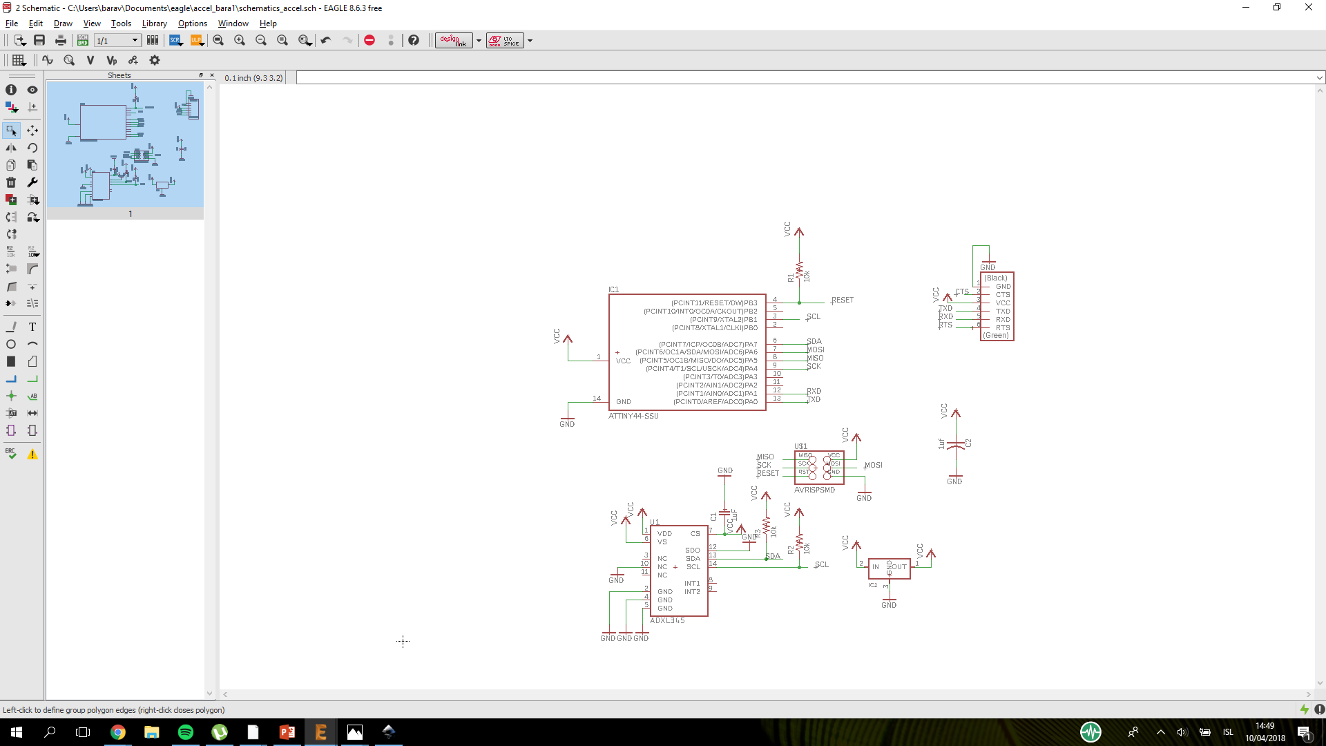
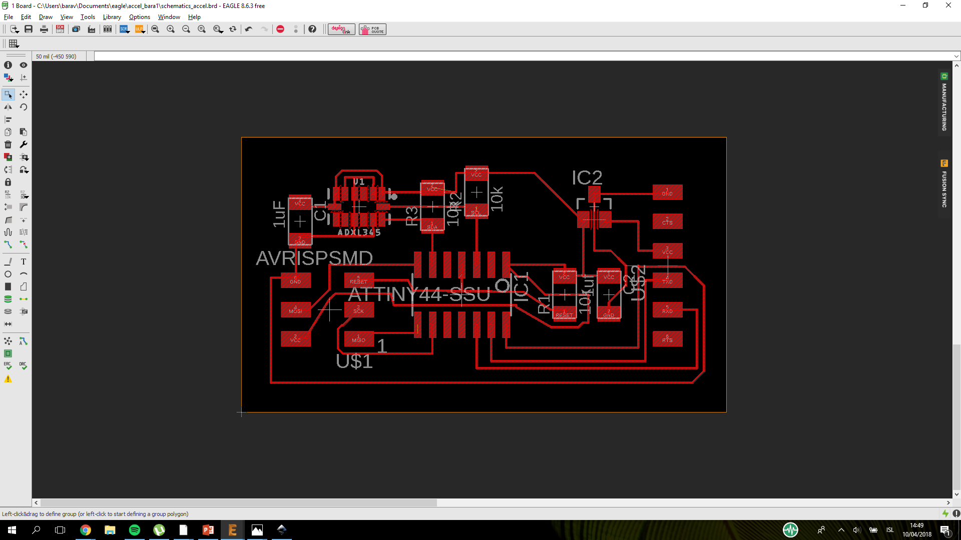
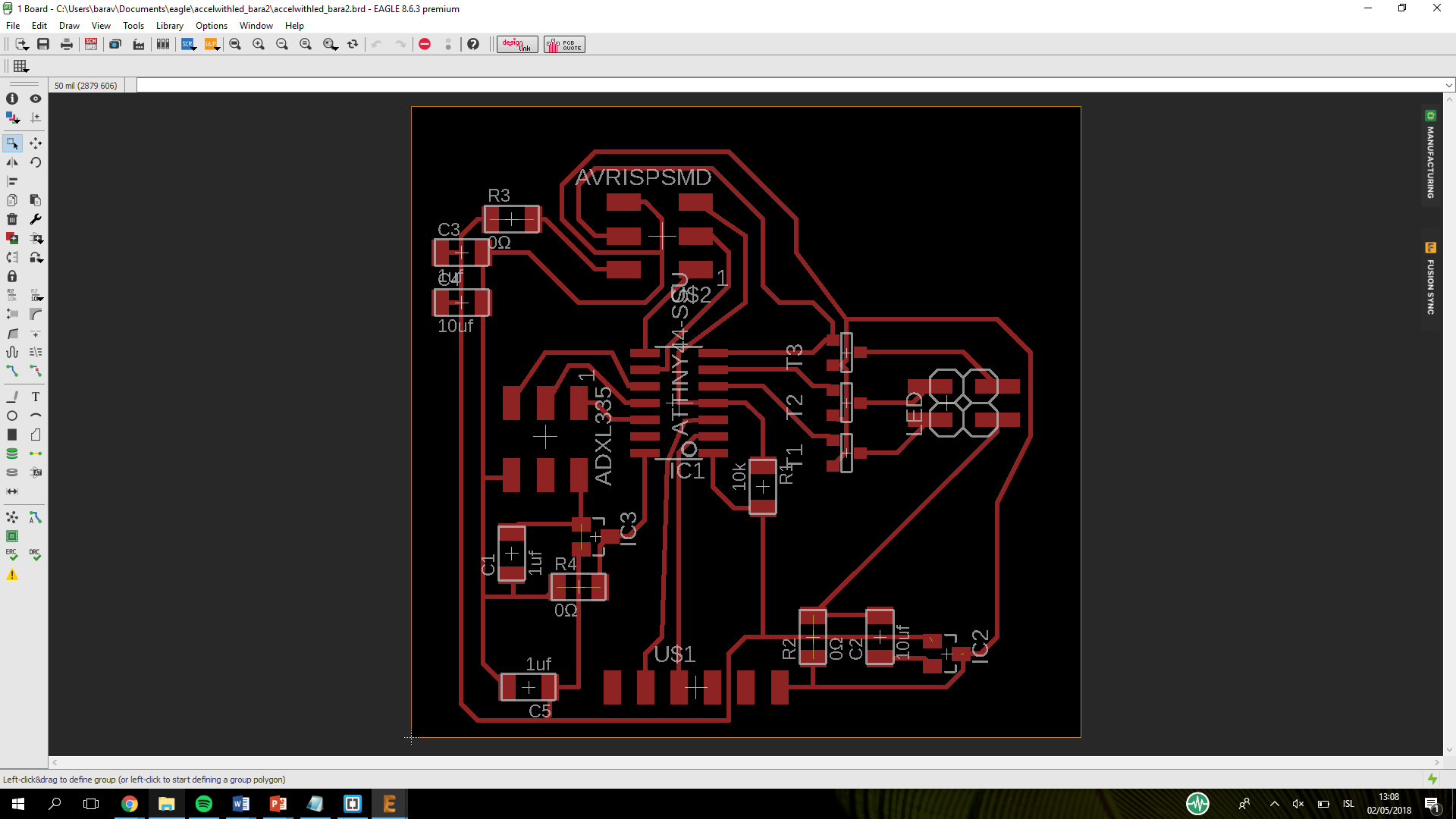
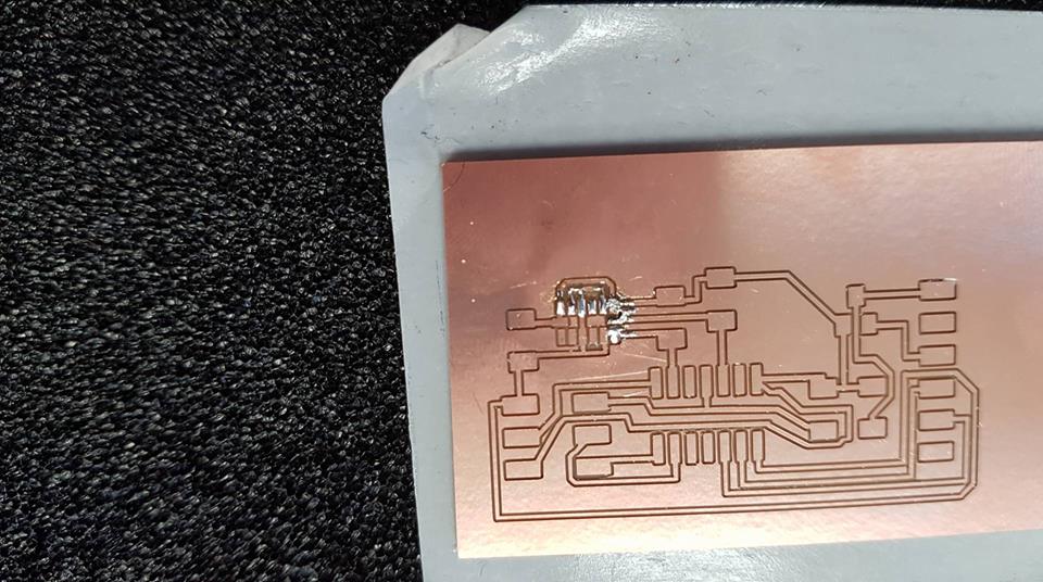
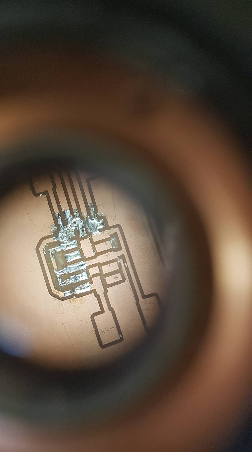
I used eagle to design the board. My inspiration was the accelerometer that Niel had already done and I also used the documentation from Jasmin Rubinovitz that did Fabacademy in 2015. I used the attiny 44 but Niel used the attiny45. I connected everything in the schematics and then in the board I used the dcr that bas showed us in the electronics design week. I drew everything and connected and after a long time trying to get everything to connect I finaly got to cutting. That however was a big failiure. The 1/65 tooth was to big for the accelerometer and for some of the lines I made. I then tried using the 0.010" tooth but it was also screwing some of the lines up so I whent back to eagle. In Eagle I realised that in the DRC the minnimum with was 3mm instead of 0.3mm. I changed that and got a few errors with the lines that I fixed. Then Eagle decided to have some proplems so when I was saving it the photo always had a big extra black space that I couldnt get rid of so I just decided to leave it. Then I was trying to make the outlines by putting a box around the board in the 200th layer but there was always a blue box over the accelerometer that made it so I could not use it. Then after a few tries putting the box over another layer I decided to make the outlines in Inkscape. That worked fine so I could finaly cut my board.
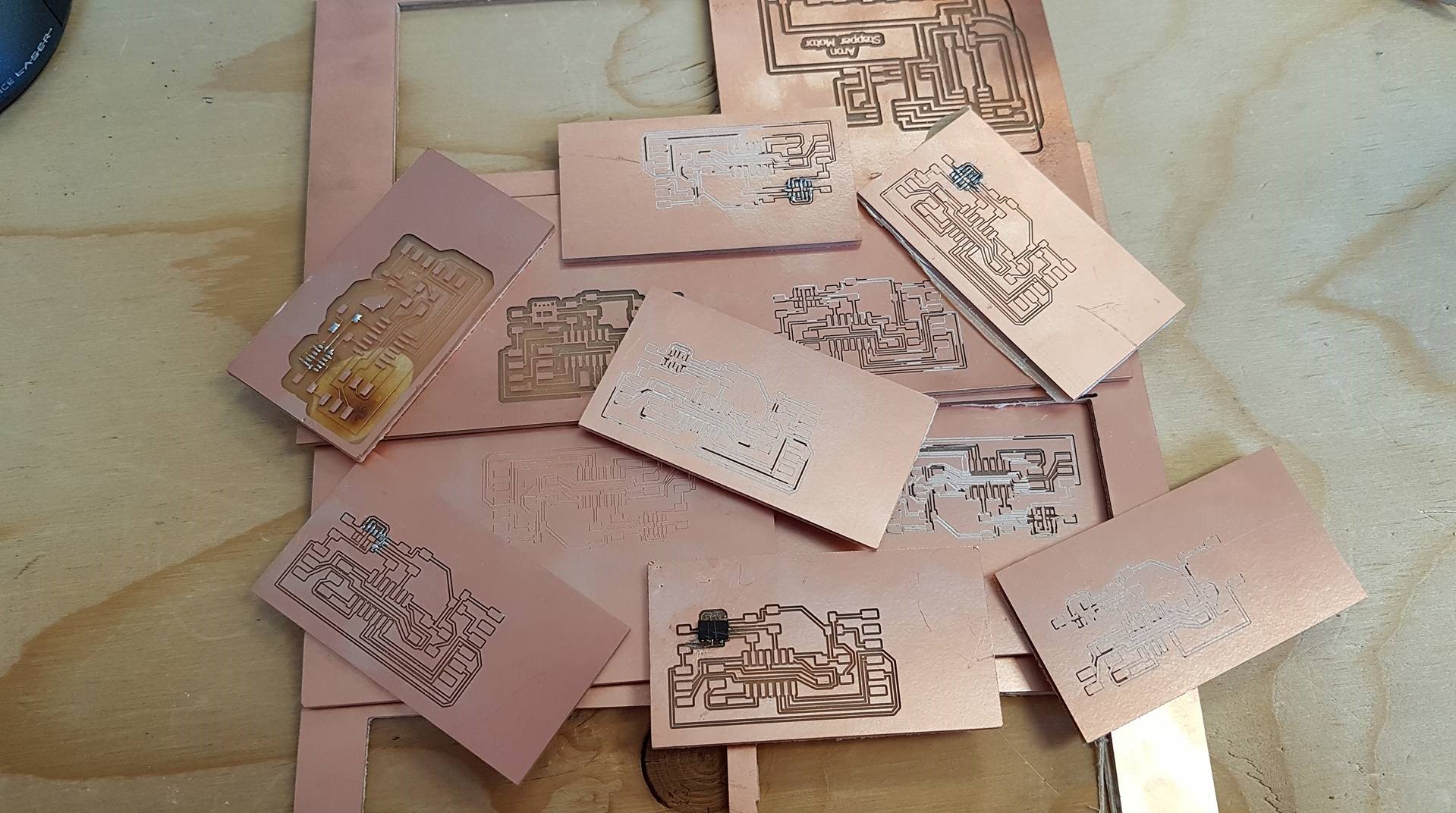
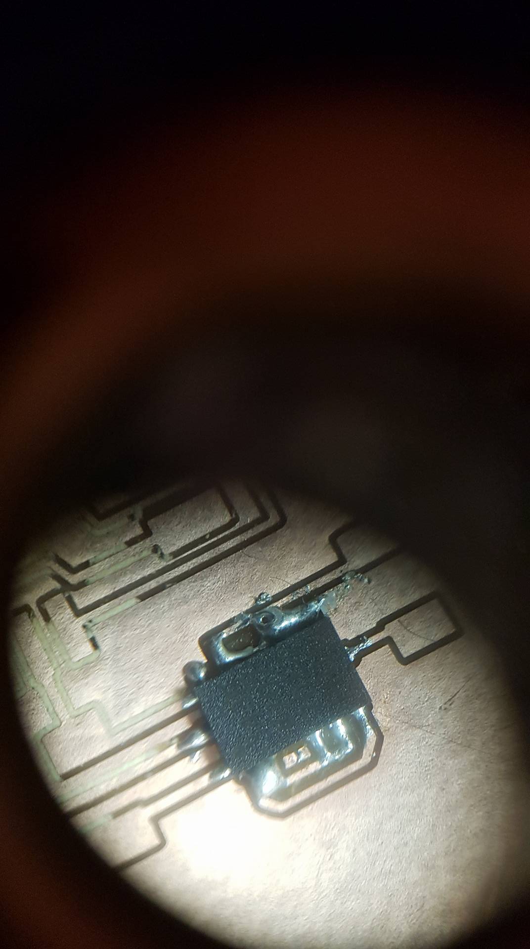
I used the smalles tooth 0.01" and the board came out good. Now comes to the hard part. Soldering the accelerometer. It took some time but I managed to solder the accelerometerin first try. Then I solderd the board. That was a big mess and the solder was flowing between lines. I tried to save it but it was not working. So I decided to mill a new board. Surprise, surprise that failed to because the tooth broke mid way through milling. I made a new board and this time it almost worked out but the outlines did not go all the way through so I just cut it out. Then I tried soldering and I managed to do the first board but when I reflowed the solder whent all over the board. So I tried soldering the other board. I tried putting less solder this time but it was not going well. Then I tried using the quick braid to fix it but it just smooshed everything all over. So I am making a new board in the milling machine. The new board lookes fine but I broke 2 tooths trying to make it. So Frosti had the I dea to start with the 1/64 tooth and then use the 0.01" tooth to finish so we are trying that out. It lookes better and there is more space between each part so it is easier to solder. We soldered it and then tried to reflow it. It failed so we tried again. Again we failed at reflowing and burned the board also the lines were very thin so they kept braking.
Plan B
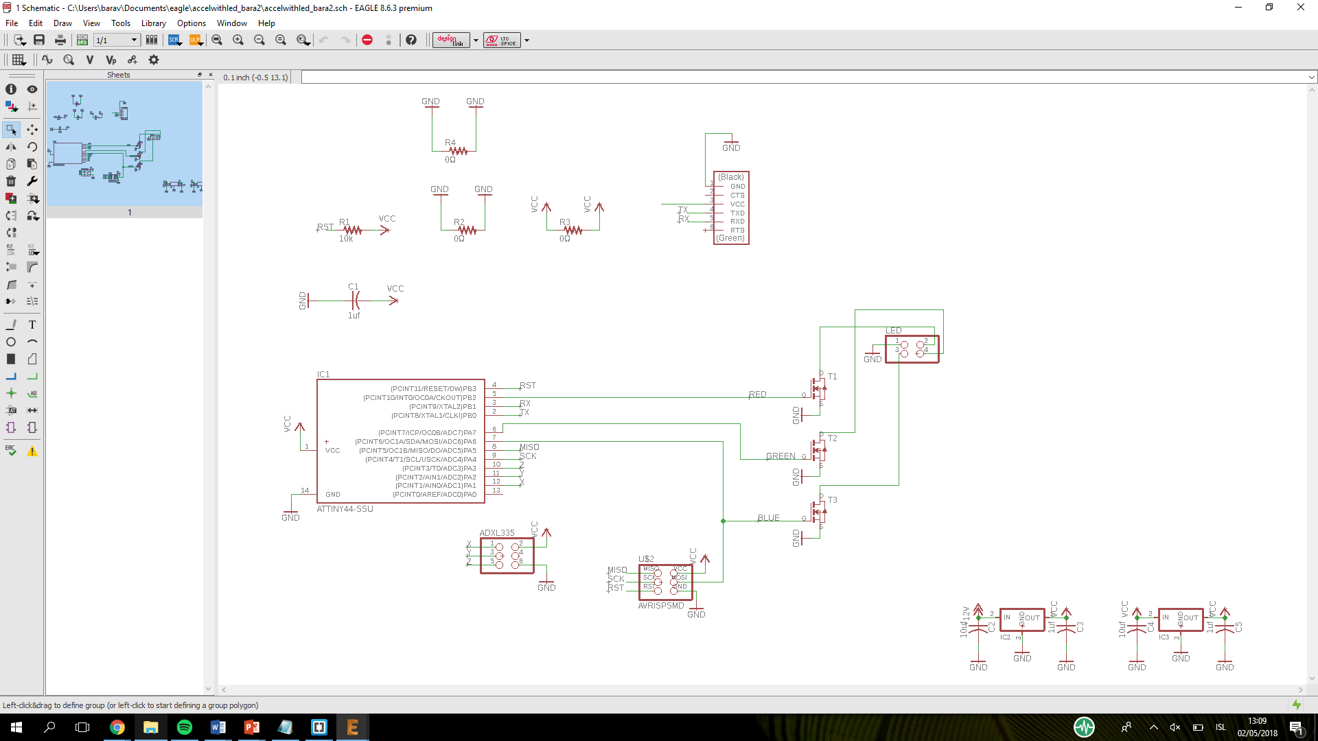
Because I was having so much trouble reflowing and soldering I decided to use the ADXL335 from sparkfun. I used the board
Arnar Sveinn made in 2016 as an inspiration. The boards are simular but he also has buttons on his board and an extra 2x2 header. The designing process was not to hard and I am getting familiar with Eagle so it is taking less time now. To save time I made the board with a 4 pin header so I can add my input device, an LED strip.
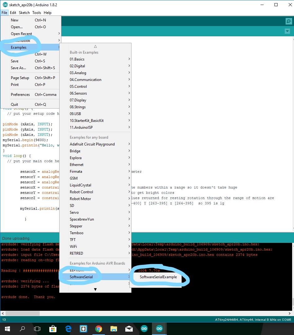
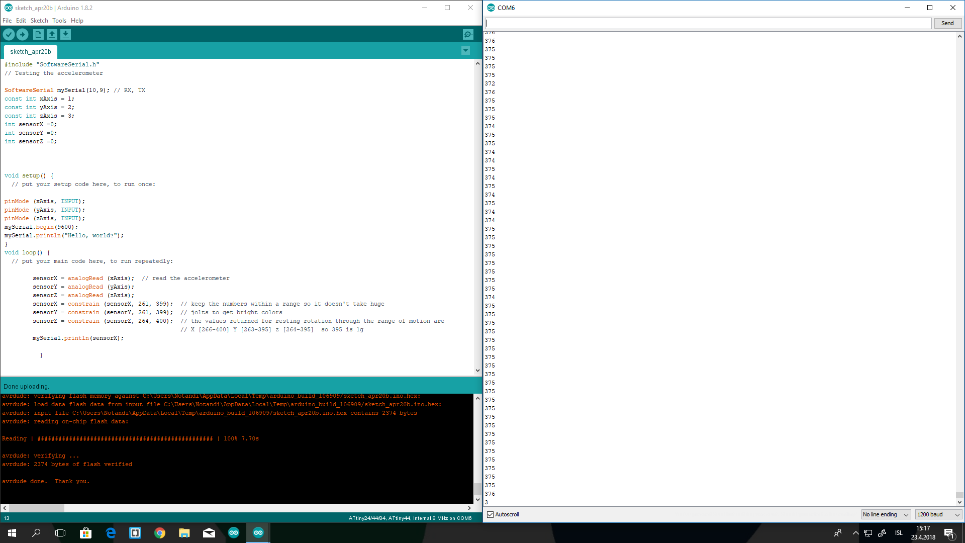
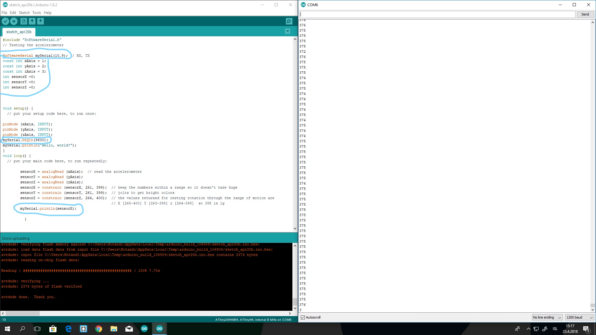
Milling is also quickly done but my outlines were not in a good quality so I had to fix them. Then Soldering is just too easy now after having soldered the accelerometer. Now I got to programming. I used Arnars program to work after. It was acting kind of wierd so Carl came to the rescue. The ISP was not talking to the port so we just took it out of the port and put it back in. We used the example from arduino for the software serial port. I put the right pins in and changed mySerial.begin to 6900 and the mySerial.printIn to sensorX then it read the sensor for x. however at the serial monitor I had to put it to 1200baud for it to give the correcct reading.
Problems and solutions
The mistake I did in Eagle was just stupid I put in 3mm instead of 0.3mm minimum line width. That can be fixed easily.
I had problems with soldering so small parts but I hope that can be fixed with practice.

I also had problems with reflowing. I have never done it before and we do not have this little extra part on our hot air gun. So reflowing was a mess. I think I put to much solder on some bits so I trying to put less solder on the new boards. Also not having the small end part is not helping so maybe if we had that it would work better.
Software I used
Arduino
-For programming.
Microsoft Photos
- For photo editing.
Gimp
-For photo editing and making the outline.
Eagle
-for drawing the circuit board
Inkscape
-For making the outlines.
Files from this week
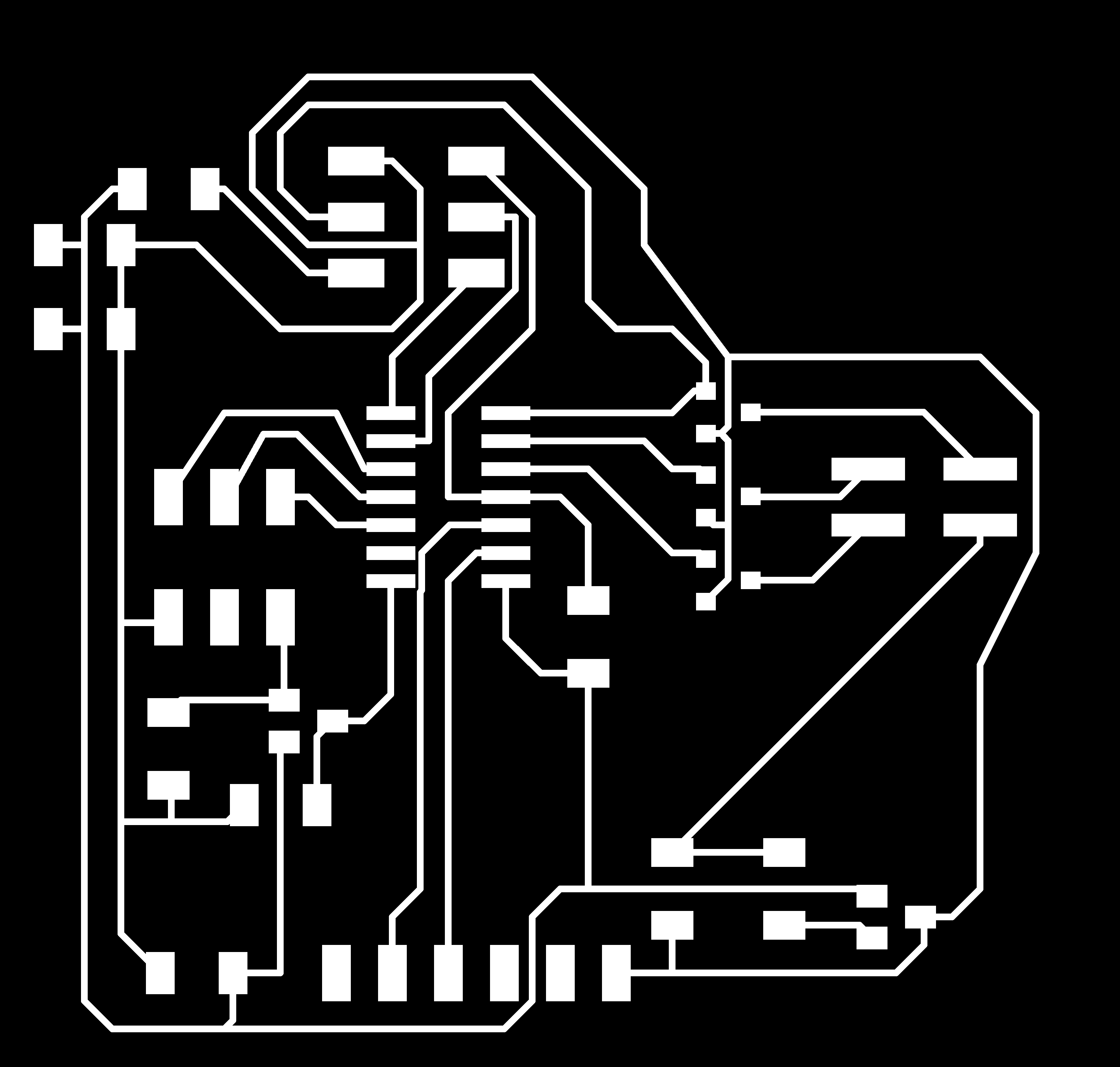

Board.
Schematics.
Code