First find everything you need. You need scissors, double sided tape, copper plate, small hexagon, milling cutter and a putty trowel.
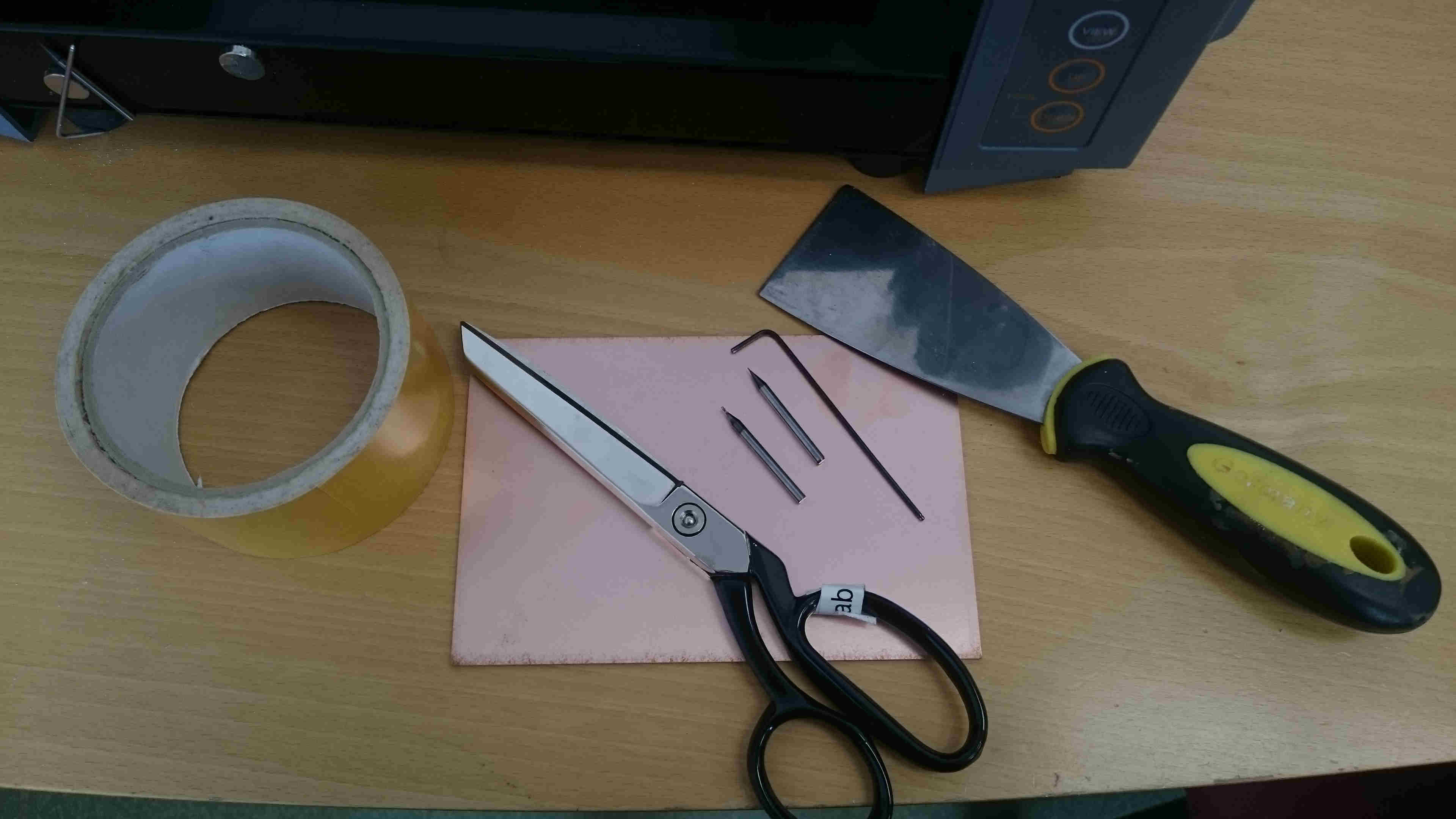
Make sure the machine is turned off and put the right milling cutter in, in my case a 1/64”,
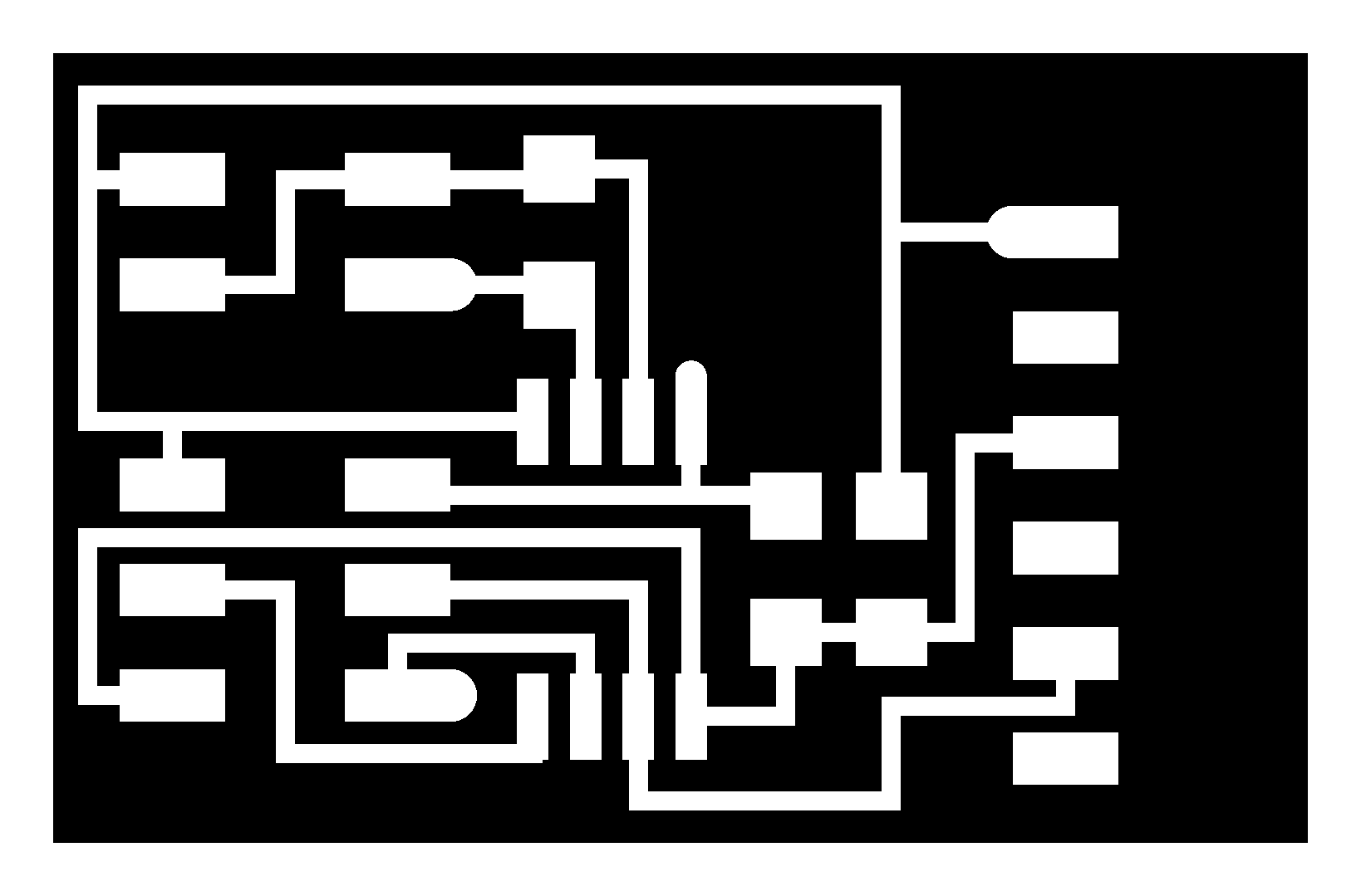
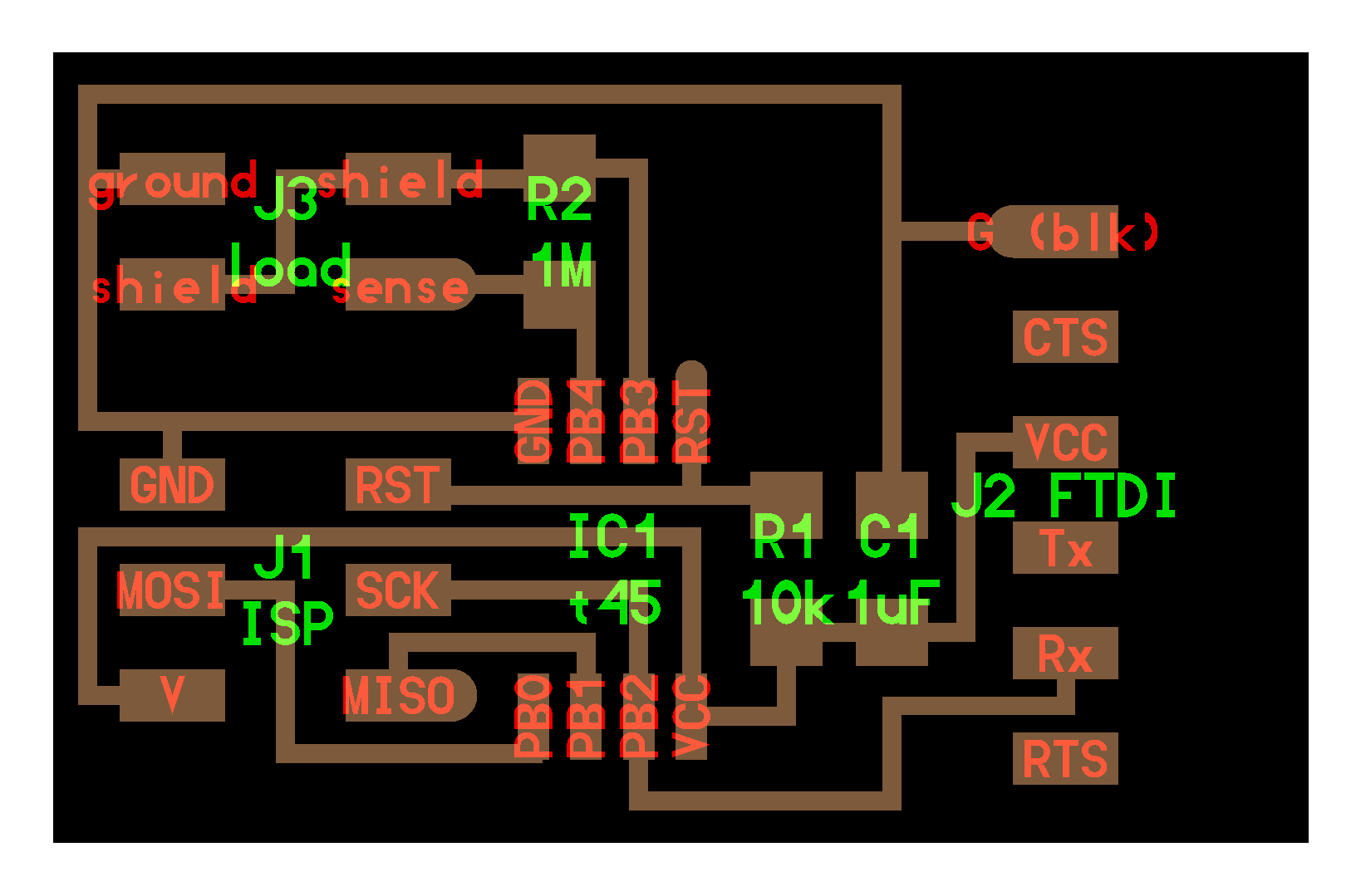
and put the copper plate on the milling machine. Download the png files for the traces and outlines. I made the FabISP from David A. Mellis.
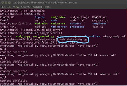
Next I have to connect the computer to the milling machine and make it “listen”. To do that I have to first turn on the machine and press view.
Open terminal in Linux, go into the folder for mod_server and then write "node mod_server.js".
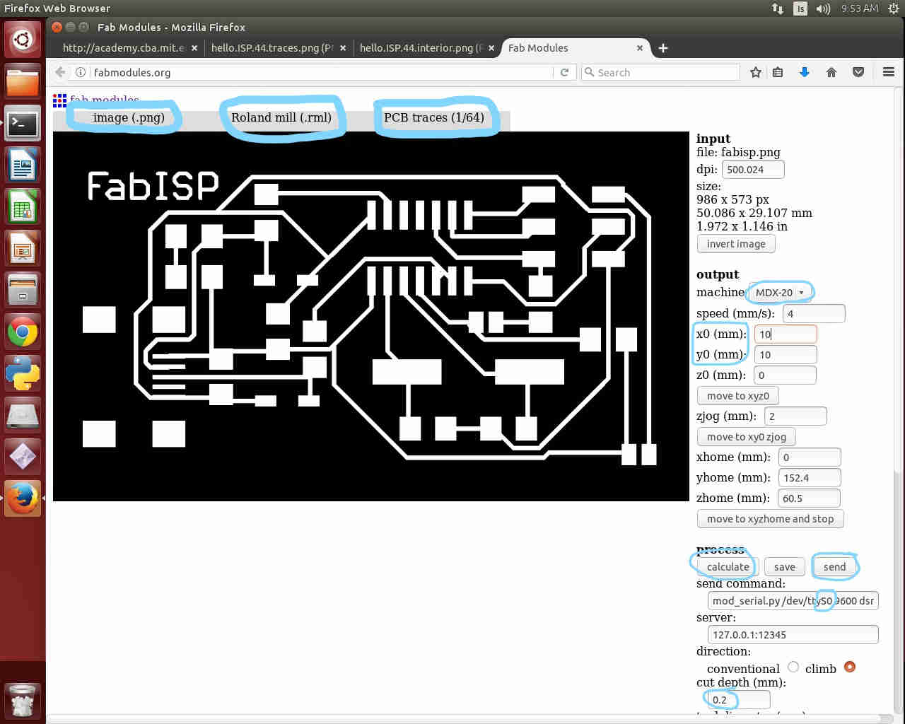
Then open fabmodules.org in an internet browser. I used the old one but you can also use the new version.
I go into input format and choose image and find the png image for the traces.
In output format I choose Roland mill because that is the milling machine we have but if you have some other kind just pick that one.
In process I choose PCB traces (1/64). In machine choose MDX-20 and choose a starting point for x and y.
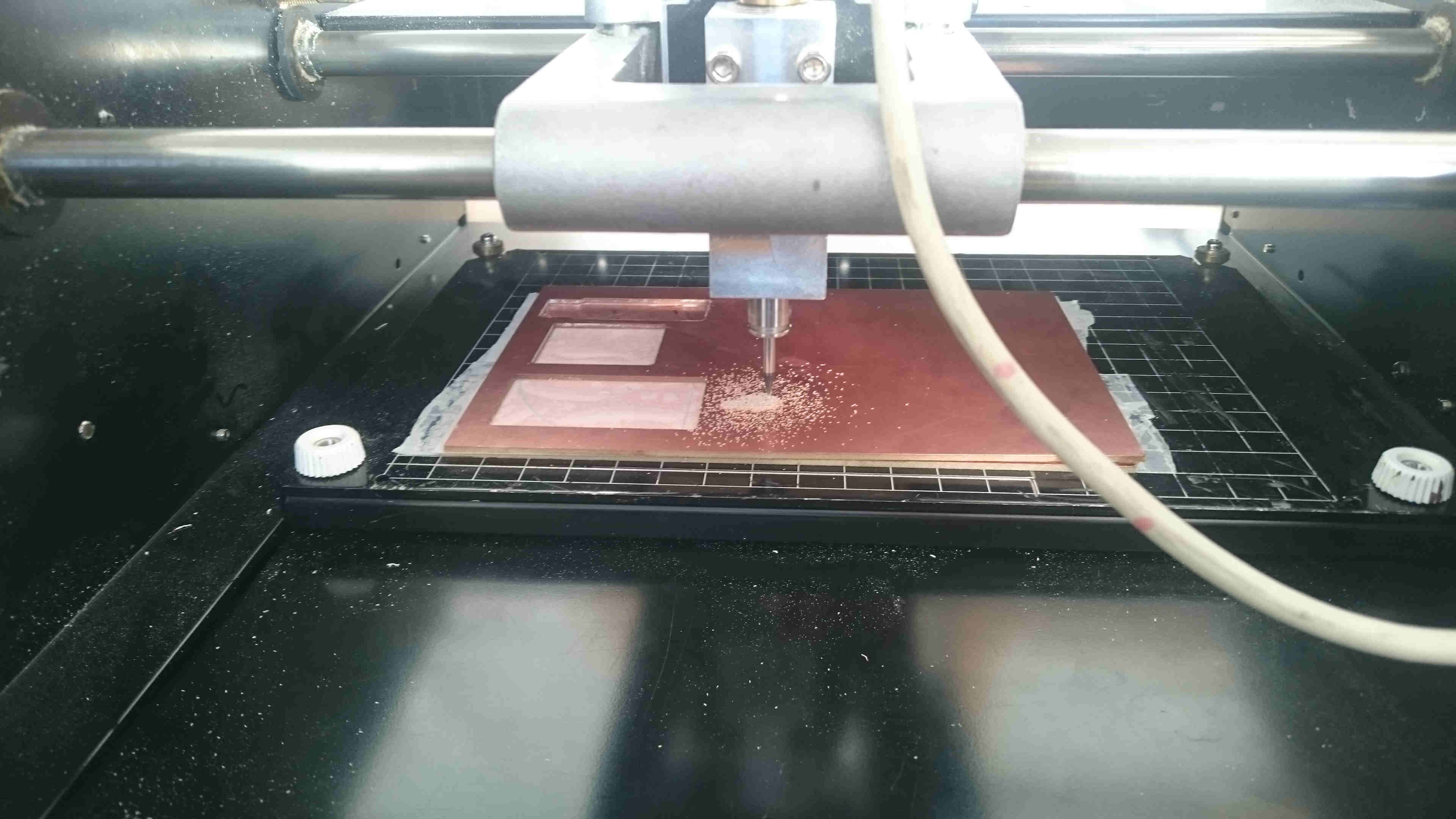
When the milling machine is in the right x-y position press the down button until it is around 12mm from the copper board,
release the milling cutter down so it touches the copper plate, do this gently so the milling cutter won´t brake,
and tighten the screw, now you have set the z position.
If the machine is connected differently then with a USB you have to change the command line,
in my case I have to take out the U and the B in USB and change the cut depth to 0.2.
Press calculate and the machine will calculate how it will cut out the hello board.
Double check if your settings are right and if everything looks good press send and the machine will start cutting.
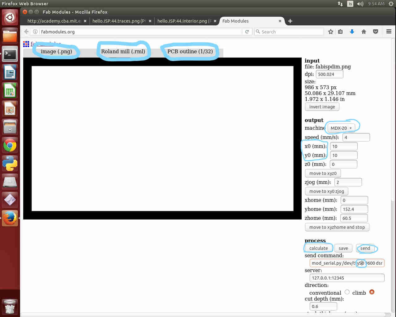
To do the outlines you have to change to the right milling cutter, 1/36”, and do everything over,
the things you have to do different is in process choose PCB outline (1/32) and do not change cut depth.
Make sure you have the same x-y position and that you press calculate before you press send.
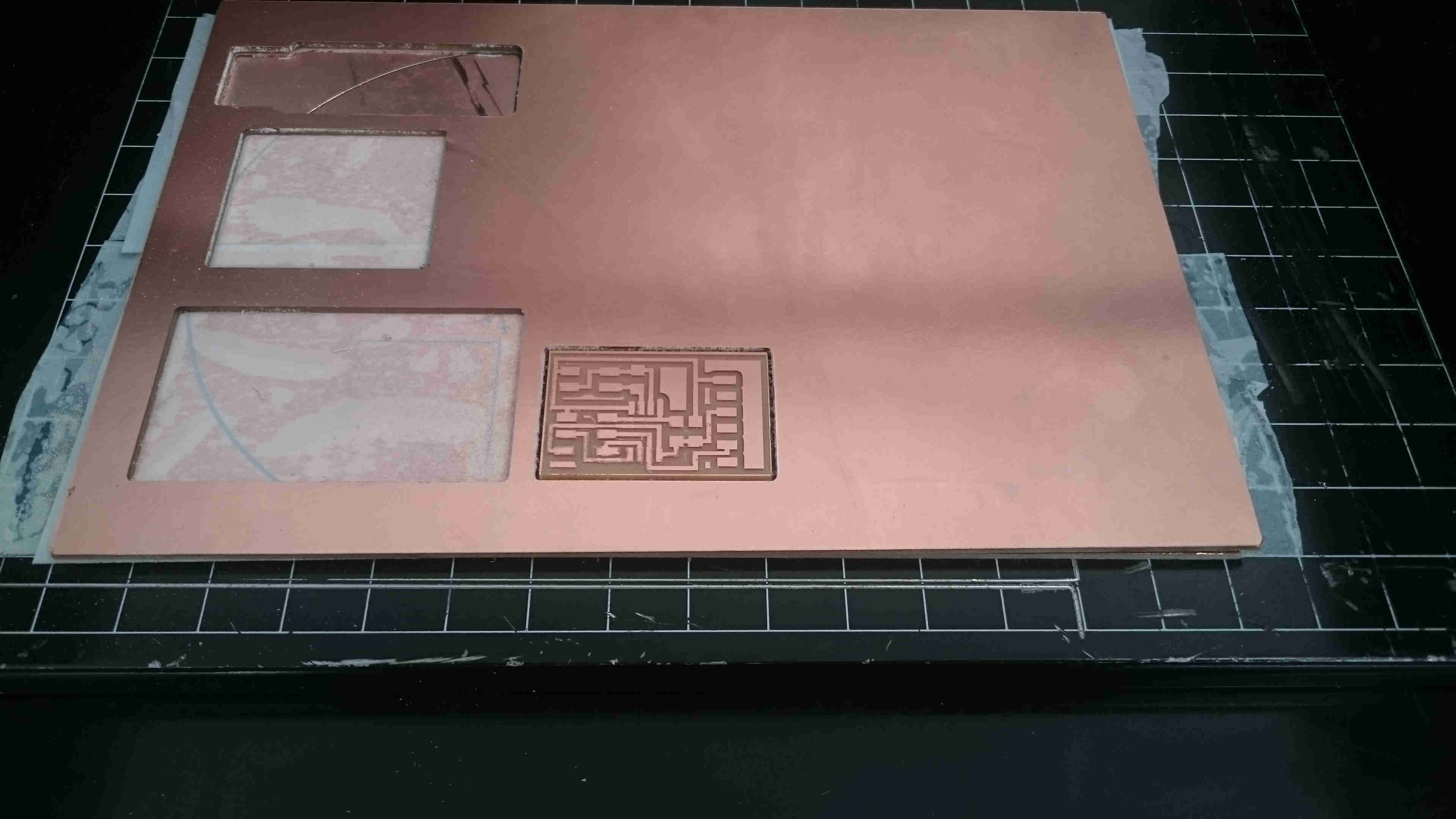
When the circuit board is all cut out press view and turn off the machine.
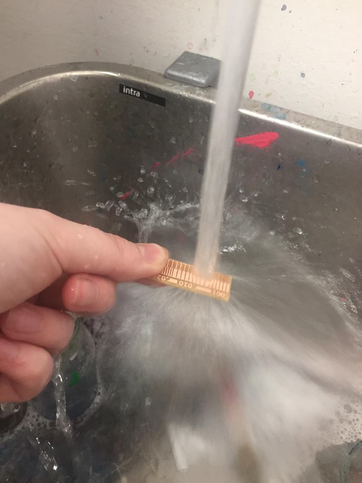
Take the board out and clean it with water and soap.
here is a video in Icelandic about how to use the milling machine
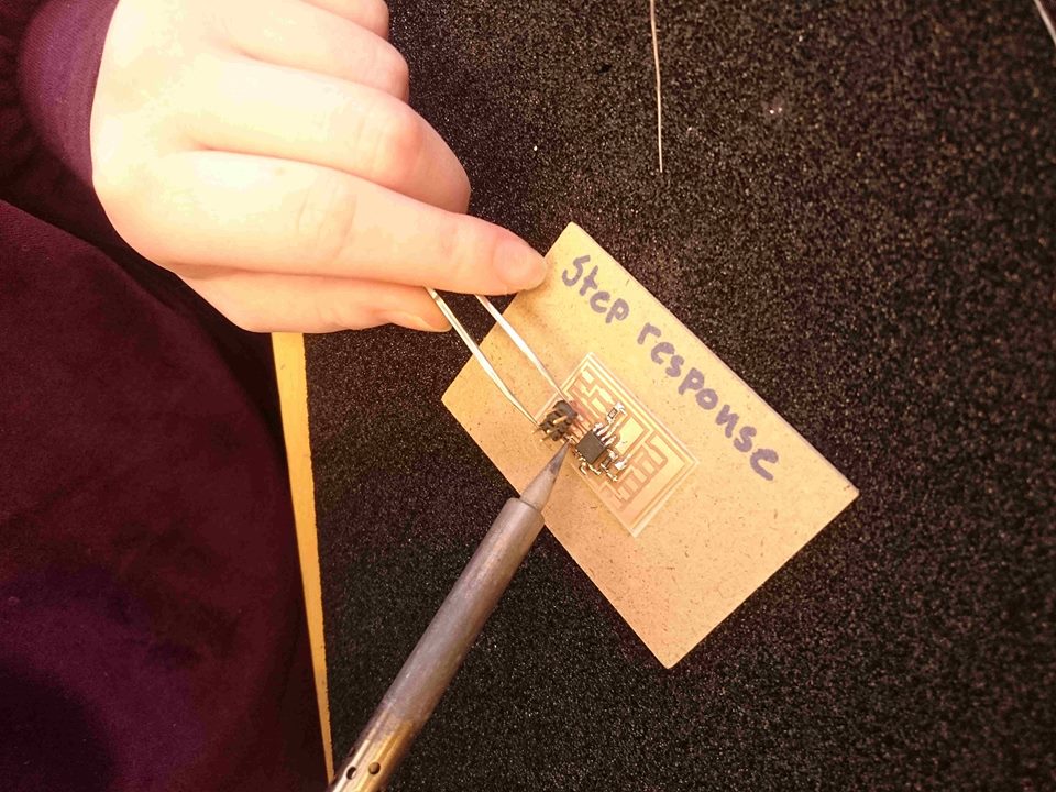
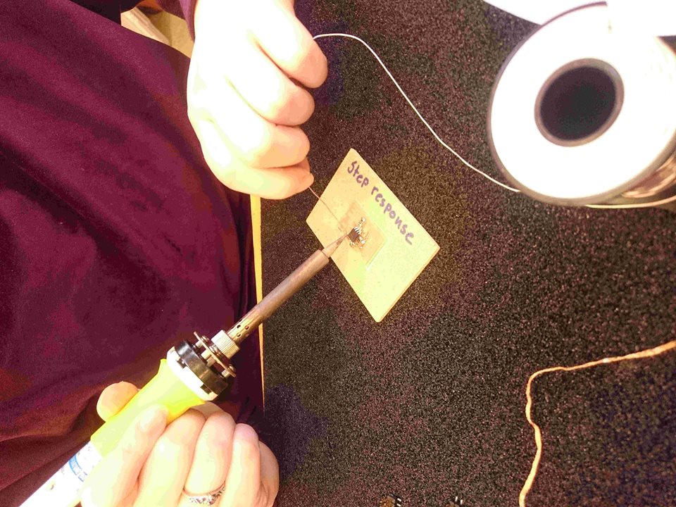
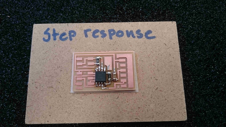
I printed the picture of the board and started soldering on the right components.
It is best to start with the small parts and end with the bigger ones and start in the middle and work out.
Some people like to find everything first and then start soldering but I like to find each component as I go.
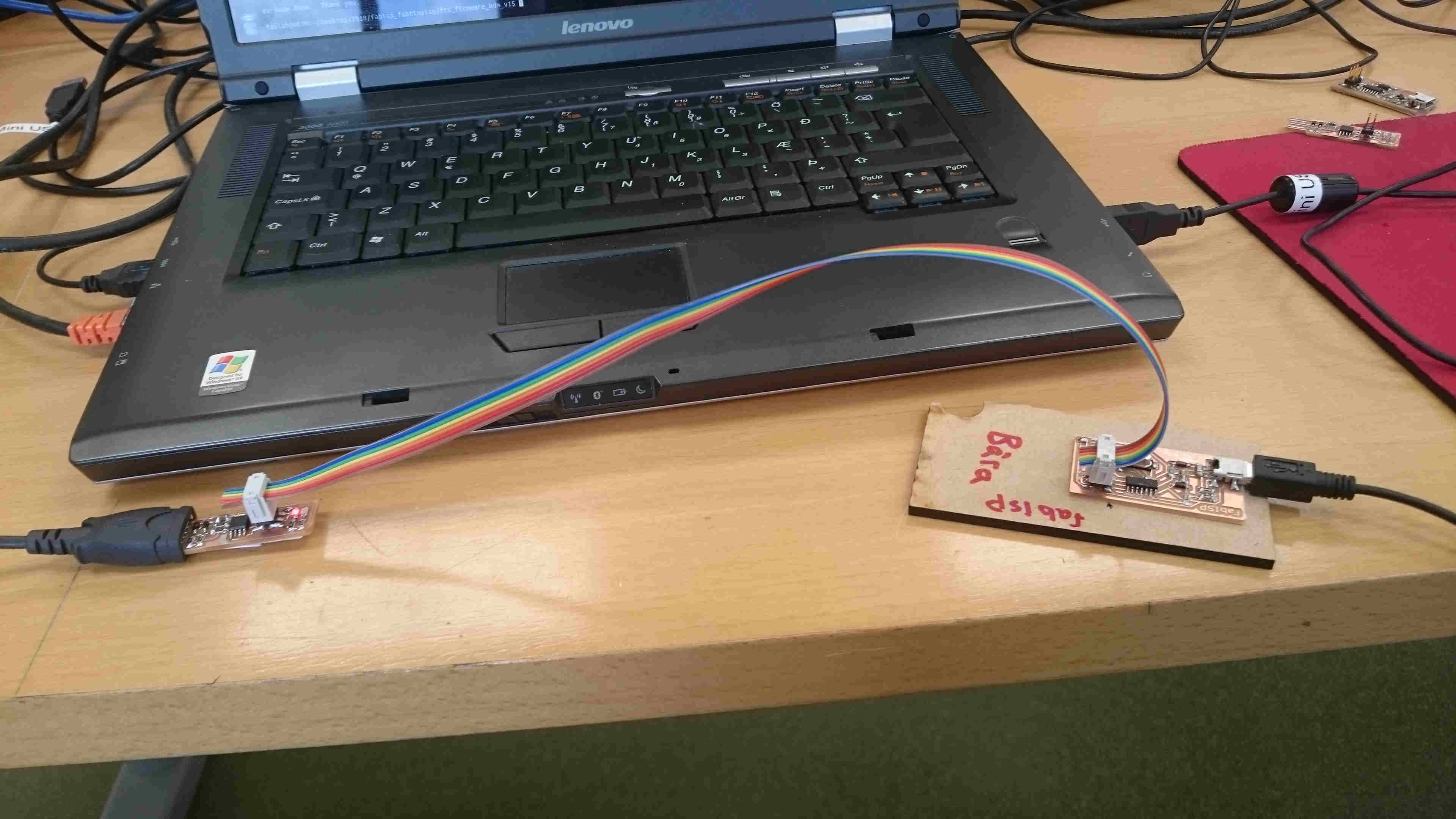
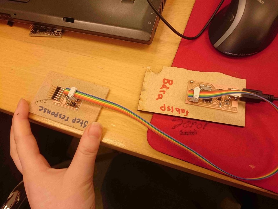
To program the circuit board I took an old fabisp from Frosti and connected it to my fabisp.
Make sure the ribbon cable is connected correctly, vcc to vcc. And that the jumper is soldered. Then save the firmware zip file, Can be found here.. Unzip the firmware using the command line "unzip firmware.zip"
Next write "make clean" then "make hex" then type "sudo make fuse". Next type "sudo make program" Now your fabisp should be ready.
_LI.jpg)

_LI.jpg)
_LI.jpg)
_LI.jpg)