Computer-controlled Machining

Week 8

Introduction

Introduction

Make something big: For this week's assignment, I chose to make a book shelf for my apartment. While shelves are generally fairly simple, this one is fitted, and the dimensions need to be very specific. It slots onto a pillar we have in our living room, and runs from the floor to the ceiling. I made it parametric, since I wanted to start designing it before I had the actual dimensions. Once I measured it, it was a simple matter to edit the parameters, allowing the design to pop into place.

For this week's group assignment, we worked with the Reykjavík Fab Academy students. We all participated in a bootcamp in Sauðarkrókur, and did the assignment as we were passing through Reykjavík.We created a test piece and measured the result. The group page is not ready yet.

Individual Assignment

Digital design for big things

Fusion 360 and woodworking joints

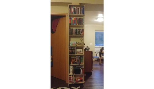
Step 1: Envisioning the shelf

First I needed to imagine what I wanted the shelf to look like. I created 3 sketches, one for each plane. I used the center rectangle tool, which draws the rectangles out from a central point. I used the center of the work-area as the center for all three rectangles. This gave me a very basic idea of what the shelf would eventually look like, at least as long as I looked at it directly from each side.


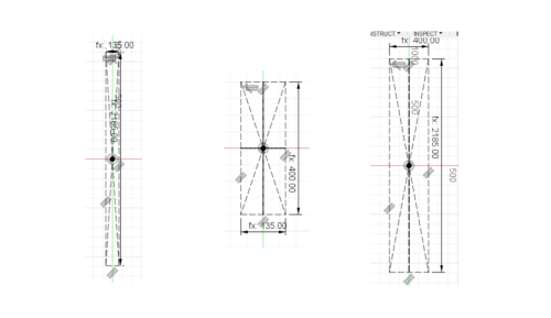
Step 2: Setting parameters

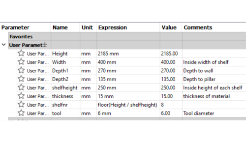
When I began drawing the shelf, I hadn't measured the pillar yet, so I only had estimates of how long each side needed to be. I therefore created parameters for these measurements, so that I could easily alter them once I had the proper measurements.

This lead me to include several other parameters as well. We have the self explanatory height, width and depth to wall and depth to pillar. I knew I wanted my shelves spaced so that they would accommodate a paperback book with some room to spare, so I included "shelfheight" as a parameter. I also included thickness of material, so that my design accounted for it as I kept drawing. Finally, I added Shelfnr, which calculates how many shelves I can include at the specified shelfheight given the height of my shelf as a whole. Using "floor(variable-Y/variable-X)" will give you the value rounded down to the nearest whole number. If I used "ceiling" instead of "floor" it would give me the value rounded up to the nearest whole number, which would have crammed one too many shelves into teh available space, and all my shelves would be spaced slightly too close together to be useful.


Step 3: Extruding and spacing the sides

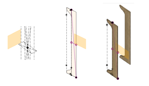
Now that I had all my measurements and parameters in place, it was time to extrude from my original sketches. First, I created a new construction plane, parallel to the sides of the shelf and in-line with the left edge of my front-view sketch. On that plane I drew the profile view of my shelf, with fins that stretched back to wrap along the sides of the pillar. I then extruded this profile by the thickness of my material, and created a copy which I moved to be in-line with the right edge of my front view sketch. Now the sides were ready.


Step 4: Drawing the shelves and choosing joints

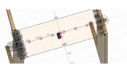
Using the top edge of the extruded sides as a plane, I created a new sketch. I projected the rectangle from my initial top-down view sketch so that I was sure that it was the right size in every way.

I looked over the many different digital joints for woodworking, and based on this decided to use hidden press fit joints for the shelves and rounded joints with wedges at three points. I drew them on one side and used the mirror function to replicate them on the other side of the shelf sketch.

50 types of joints

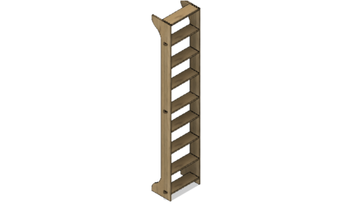
Step 5: Extruding and spacing shelves

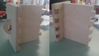
I drew both of the different types of shelves on one sketch, then simply extruded them into two different components from there. I did this because they use a lot of the same sketch objects, with only a few key differences. While most of my shelves simply slot into the sides, three of them go through the sides, and when wedged, these joints hold the shelf together. This allows me to assemble it without screws.

I used the "create-pattern-rectangular" to create "nrShelves" amount of shelves. I did not expand sideways, and I unticked the little boxes where I did not want the shelves to be placed. Once I had all my shelves in place, I used them as tools to cut little pockets and holes in the sides, so that the shelves would slot into the sides neatly.


Step 6: Create dxf files from relevant planes and export

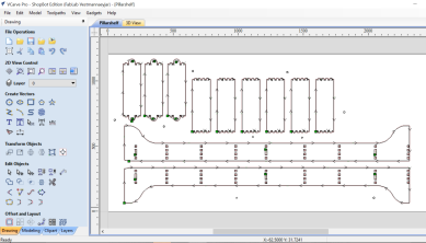
To export my design to v-carve, I selected each component in turn, first the inside of the right side, then the inside of the left, then the shelves that go through, and finally the shelves that do not. For each one, I selected them, then created a new sketch based on that surface. I named these sketches for their components, with the suffix ".dxf" so that they could be easily identified as the exportable sketches. By right clicking, I could save the sketches as dxf files, which could then be opened in v-carve.

If I had known then how easy it is to create toolpaths directly in Fusion 360, I would have skipped the following section, but alas, I only learned that later.


Bringing the digital into the physical realm

Converting to V-carve, then milling in Shopbot

Testing specs

I created a test for my joints before cutting the whole project, just to be certain that my dimensions and settings were okay. The test came out beautifully and all the joints were correctly sized. The tool settings were fine for the project as well.

When milling it, we discovered that the path was very inefficient. The drill would jump back and forth instead of cutting it in one smooth circuit. The reason was that the space between the "fingers" was too small. I added the "tool" parameter to the fusion design to compensate, after which the path became more efficient. We reduced the production time by half an hour as a result.


VCarve

I measured the size of my material, and input that as the sheet in Vcarve. I then aligned my pieces on the area so that the grain on the shelves is all the same, and all my pieces would fit. I added a separate drill path which I cut first, into which I drilled additional screws to fasten my material to the sacrificial layer. I did this because my design is very long, and once the longest pieces were cut, the integrity of the material would most likely be compromised, causing it to bend and flex when cut.


Default settings in our lab

In our lab, we don't change the milling bit very often. We primarily use a 6mm flat upcut end mill with 3 flutes. I was in a hurry, and decided to just use the same bit for this project. If I were to do it again, I would probably have chosen to split the depth in half, first milling the top layer with a downcut bit, then milling the rest with an upcut, since then the finish would be smoother, and there would be less splintering at the edges. I also just used the same spindle speed and feed rate as every other project on that Shopbot used at the time. If I were to do it again, I would consult material guides for 9mm birch plywood as well as the specs of this specific milling bit before milling the project. I would also use this handy speeds and feeds calculator to use the proper speeds and feeds because it is important. If you don't, you could damage your bit, and will receive inferior milling results.

Speeds and feeds

Safety first.

Don't operate the machine without an experienced person instructing you the first few times. After that, don't operate it without another person nearby who knows how to push on a red button if required. Our machine is improperly grounded, and is connected to an old PC computer. We move our designs onto a temp folder on the desktop, then disconnect the computer from the internet and disable virus protection. We place our material on the workbed and carefully secure it with screws.


Shopbot PRS-alpha

We have a Shopbot PRS-alpha, with a work area of: 1440 x 2190 x 150 mm. Our Software is called "Shopbot 3". To zero x and y, you first have to tell the machine to go to absolute zero, then move it to where you want the machine to start, then zero the x and y axes there. Write down the coordinates of your new zero positions for x and y before you make them your zeros, because the gremlins will make the machine forget about them when the it crashes, and this allows you to start again from the same zero position.

Shopbot PRS-alpha Changing milling bit Shopbot manual in Icelandic


Zeroing the z axis

First check that your z-axis zeroing plate is connected by pressing it carefully against the bit. If you get a green signal on the board, you're good to go. Place the zeroing plate on top of your material directly below the bit, and tell the machine to zero itself (c2[enter][enter] on the bot). Ask the instructor standing next to you if you're uncertain about any of this. If he or she is any good, they will have fingers, and can point at the things you should be interacting with.

Shopbot PRS-alpha

Shopbot and final product

Our shopbot has gremlins, and froze three times during my milling process. Each time, I removed the pieces that had been cut so far, since I know that if you're uncareful they can be damaged by the tool when you resume the process. I was careful, but still made a few mistakes. At first, my design was too wide, a quick rearrangement of parts got them back in place. Secondly, the second time it froze and I resumed the print, I didn't first have the tool return to zero, so it didn't resume its position correctly. The third issue is that I had to climb into the machine (I turned it off first, of course) to reattach the dust skirt which falls off sometimes. When I did, the tool lost it's zero for the Z axis, and went about half a cm too deep. I stopped the machine, zeroed the Z axis again and resumed.


Files and advice

The files for this shelf are here. I recommend opening the fusion file first, since you can then modify the parameters to suit your needs. In order to export DXF files for VCarve follow the instructions in the video I linked above. I recommend arranging the pieces carefully to avoid damaging your machine.

Remember to adjust the "tool" parameter in Fusion to match the diameter of your milling bit.

Fusion 360 shelfDrillpathShelfpath

conclusion

I want to make more furniture for my home, and will certainly use the same method. Using the shopbot can be intimidating at first, but is not that much more difficult than the laser.

Next page Fab Academy