Stepping stones
Finding my way through winding paths

Inkscape
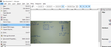
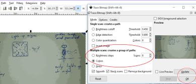
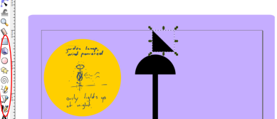
Inkscape is the vector graphics illustration program I am most familiar with. I imported my concept drawing to Inkscape and used "trace bitmap" to convert it to vector format. I then drew a better concept of what I want the profile of the Will o'the Wind to look like.I also drew it from the top, to get an idea of the relationship of the blades of the turbine.
The biggest challenge at this stage was to wrap my mind around the internal mechanisms. Knowing their dimensions will be essential to designing the exterior as well. The biggest challenge later was to describe this process beyond what I already did in the above paragraph.
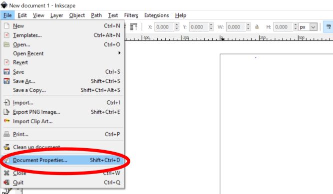
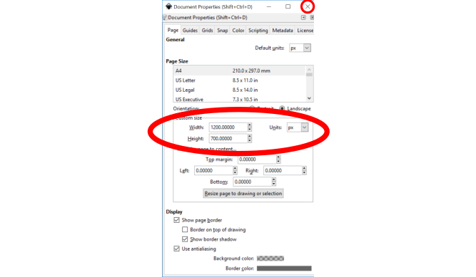
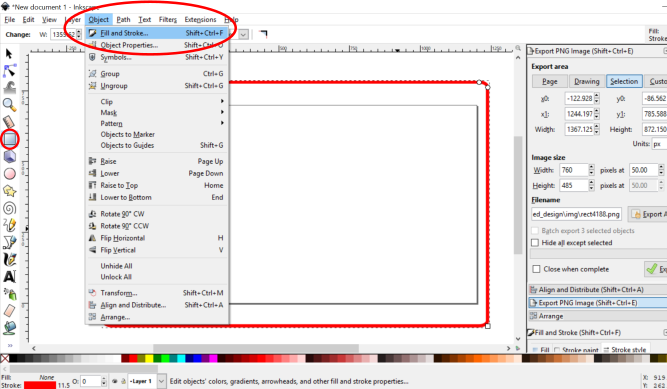
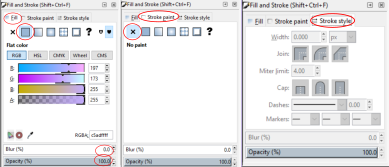
I could see no reason whatsoever to save the original svg for this image, so I had to redraw it later because for some reason I can't graduate unless I showed you the extremely boring details of how I went about using a program I use every day.
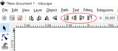
Inkscape step by step guide on how to draw a very simple image in Inkscape. WOW! Brand new original svg file, BAM!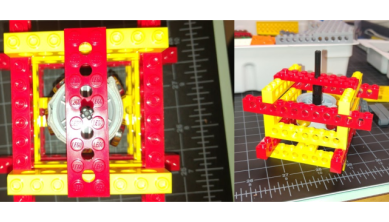
Using LEGO to visualize my concept
I wanted to get a better feel for how the internal mechanism works, so I built the core of the model out of lego, to which I taped magnets. I considered winding copper wire around it, but decided against, since it seemed wasteful at such an early stage.
The benefit of this approach is that it's safe, which allows me to focus more on design aspects than on learning new terminology and keyboard shortcuts.
Youtube video about making a small generator
Instruction videos!
Luckily for me, there's about a million excellent instruction videos for Fusion 360 beginners. I watched this video which Linda Wanders shared with our Facebook group. I also found a series on youtube called Fusion 360 for absolute beginners which was very helpful.
Youtube video on parametric design Youtube videos for absolute beginners Fusion 360 for students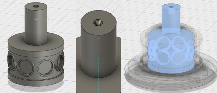
Initial Design
I used the center circle tool to create my first pieces, using measurements of some of the magnets available to me to create the mag unit. On top of the mag unit I used "create: thread" for fastening it to the turbine. I then crafted the coil unit around the mag unit, so that they would fit around each other with 1 mm of space between. This should allow the mag unit to rotate freely. To be added: Bearing for mag unit!
Thingiverse tutorial on slew bearings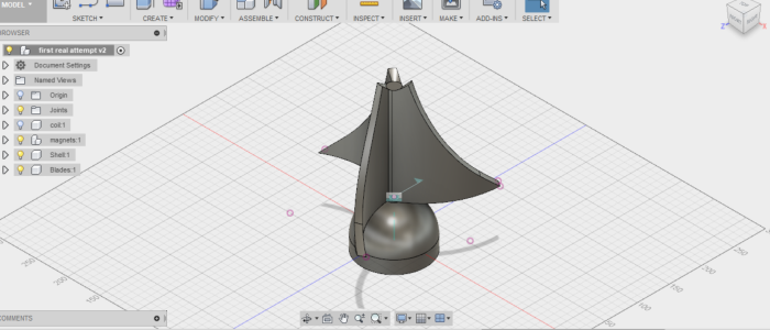
The first turbine design
This was the first version of the assembled four pieces. I used joints to make the turbine and mag unit rotate. I grounded the shell, so that I could rotate the other pieces at will. I cannot even describe how happy I was when I pressed "animate" and it actually spun!
My turbine design is derived from the design developed by Icewind, an Icelandic company that specializes in small scale wind power in Icelandic conditions.
My first attempt was far too slender and not curved enough.
Icewind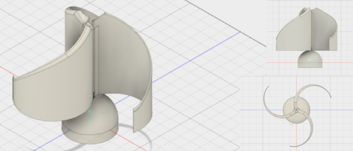
Turbine v.2
I redesigned the turbine to make it more dynamic. I drew the outline from the side, the used "revolve" to make a circular shape around my center axis, which was a construction line I drew earlier. Then I tilted my view to look at it from the bottom, and drew two differently sized circles, their center points 5mm apart, under the base of my shape. I "extruded" the area between the two circles upward and used "intersect" to create the shape.
The wing was not aligned with my central axis, so I used the "align" tool to align it properly. Then I could use the "pattern" tool to create two more wings, distributed evenly around the central axis.
Video on terminologyAnimating the model
I used the join function to create a rigid joint between the turbine and the mag unit, since they should spin together. I then grounded the shell, and created a revolve joint at the central axis of the turbine and the shell. Embarrasingly, I discovered later that it's spinning the wrong way!
To record my screen I activated the xbox screen recorder included in the default Windows 10 installation. To do so, one needs to log in to the xbox app, open the program (Fusion 360 in this case), and hit the windows key and G. This opens a handy toolbar for recording, and the video can be trimmed in the xbox menu. It is intended for streaming gaming videos, but works for other applications too.I also tried Camstudio, but it was very laggy and buggy on my computer, and the videos were in poor quality compared to the xbox recordings.
Guide to using the xbox recorderFixing the revolve joint to spin counter-clockwise
Of course, I could have just loaded the video in reverse and left it at that, but I decided to look up my issue, and the fix was relatively simple. When creating the joint one needs to keep an eye on the little flag that indicates the default revolve direction.
After fixing the revolution direction I rendered my model in Fusion 360. I changed the material, the color, and just for fun, I put in a background and some lighting. I also used Inkscape to make a logo to use as a decal on the rendering. The whole process was surprisingly straight forward. My only issue was an incomplete component. Until I removed it, my model couldn't be rendered.