Computer-controlled Cutting

Week 4

Introduction

Introduction

This week's assignment is to cut something on the vinyl cutter. I am very interested in making flexible circuitry on the vinyl cutter, but if that proves too complicated, I can settle for designing and printing a logo for the project, as well as perhaps a qr code that links to my page.

The second part is to design, make, and document a parametric press-fit construction kit, accounting for the lasercutter kerf, which can be assembled in multiple ways. For this I would like to showcase and fine-tune my Bunobe units. They are not related to the lamp, but they are kerf-aligned units that can be assembled in all the same ways you can assemble Sonobe origami units to create complex mathematical shapes, such as dodecahedrons and icosahedrons.

For the group assignment this week, we get to characterize our lasercutter with test parts of various settings and dimensions. It should be fun and interesting to fine-tune our printer to the materials we have on hand. In addition, this will let us cut things with greater precision and success in the coming weeks.

Group Assignment Vinyl cutter Parametric origami units
pdf and svg files for Vinyl Cut project files for parametric laser project

Computer Controlled Cutting

Dual-color vinyl design

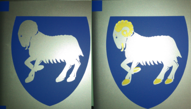
The Coat of Arms of the Faroe Islands

I am from a tiny country in the North Atlantic Ocean called the Faroe Islands. If you draw a triangle between Iceland, Shetland and Norway, the Faroes lie in the middle of that triangle. For the vinyl project this week, I chose to make a vinyl version of the coat of arms for my laptop.

I found the image online, but although it was an svg file, it was not ready to be cut. The lines criss-crossed all over the design, and it would have been a terrible mess. I refined and simplified the image until I had two colors in individually distinguishable pieces that could be cut with ease. I cut them, peeled them and stuck one on the computer first, then the second. I drew squares to help me align the design, but it still wound up being slightly misaligned.

Wikipedia about Faroe Islands

Editing and Refining

I used Inkscape to edit the svg file. As you can see, the original had many suporflous and criss-crossing lines. I used "path" - "simplify" (CTRL-L) to fix some of these issues, and used the "edit path by nodes" tool (F2) to manually delete and move any misbehaving nodes that remained.

Additionally, some of the shapes drawn up did not need to be there at all, so using the same tool, I selected them by clicking on them, then pressed "delete" on my keyboard to make them go away for good.

Original svg file

Cutting

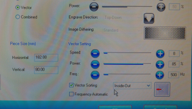
We have a 10 year old Roland Vinyl Cutter. I turned it on my pressing the big power button. First I placed a scrap of gold colored vinyl into the machine. I pushed it in from behind, and moved the wheels so they were on the edge of the material, yet on top of the white pieces of tape which are there to ensure that the material is positioned so that the machine can cut it precisely and efficiently. I fastened the wheels by lifting the lever at the left side of the machine. I pressed the down button on the cutter to select "piece" then pressed "go" which caused the cutter to measure my piece for me.

In the computer, I opened the pdf file of the details for my project and pressed "CTRL-P" to open the printing menu. There, I clicked on "get dimensions from machine" and clicked OK. I repeated the last step because our machine is a teenager and needs to hear everything twice. I then made sure that the size of my design was not adjusting to the size of the scrap but using the size that I had drawn it in. Then I pressed "GO" and the machine cut the design.

Now I placed a blue roll of vinyl in the machine, and instead of piece, I selected "roll". I then opened the second pdf file and followed the same steps as before, except I manually set the "height" to be the height of my design plus 1 cm.


Cutting

I peeled away any vinyl which was not part of my design, then placed transfer paper over the design, rubbing carefully to make sure it stuck properly. Then I removed the backing paper and carefully positioned the design where I wanted it to go, first the main design, then the details. I rubbed it well in place, then removed the transfer paper.

There are no pictures of this part of the process because it did not occur to me that it was worth documenting.


Computer Controlled Cutting

Adventures in parametric design

Origami and Sonobe units

Origami is the art of folding paper to create complex 3d shapes without cutting or tearing the paper. To me, it is an excellent aide in teaching 3d thinking, since it is at its core the art of transforming a plain 2d object into a 3d object. One of the most powerful origami patterns is that of the Sonobe unit. By combining multiple units one can create complex mathematical structures such as icosahedrons and dodecahedrons.

Last fall, I decided to attempt to recreate the Sonobe unit in wood using the laser cutter, press fit construction and living hinges. I drew it in Inkscape using the tabbed box maker extension While I created a functioning pattern this way, it has several drawbacks, one of which is that it is not parametric, so if I wanted a different size, I would have to start from scratch. I named these units Bunobe.

Tabbed Box maker

Parametric design in Fusion 360

I decided to continue working with Fusion 360 to recreate my Bunobe units as a parametric design, with adjustable material thickness, unit size and kerf. Initially I attempted to create the living hinge component as a parametric object as well, but repeated failures eventually convinced me that living hinges should be left as a fixed size that is constrained to align with a specific axis on the module. This also ensures a better functioning and more reliable hinge.

My first failed attempt was a mixup where I forgot to keep my construction lines in a separate sketch, so they transferred along with the shape. Additionally, the lines did not show on the 3D rendering.


The arrowhead hinge

This type of hinge has proven to be exceptionally flexible, but turned out to be rather difficult to draw. Each hole of the hinge has at least 14 lines, each line has several constraints telling it how to behave, each one was obeying 3 or for parametric measurements, and each time I made a parametric change the computer needed five minutes to compute the new drawing.

I learned a lot about constraints and anchor points during this exercise. As you can see, I had to redo them several times, since more often than not, a change in the parameters sent the shapes into new and unexpected configurations.


The oval hinge

Creating the oval hinge was an attempt to reduce the amount of lines and constraints required in the constructions.

This worked fairly well, but was ultimately abandoned because I realized that as the laser would draw the ovals, the material was highly likely to catch fire, since it would naturally draw an entire oval before moving on. With each line so close to the previous, once enough had been drawn to provide lots of airflow, it was a recipe for combustion more than anything else. I did test this design as a 3d drawing which was successful and gave me hope for the continuation of the project.


The (first) final design

Finally, I discovered that the hinges should be as simple as possible. I drew them up using the 3-point rectangle tool and mirroring them over the diagonal axes within the units. This time, redrawing the units from scratch took only about an hour, because of the experience I gained working my way through my failed attempts.

By this time, I have discovered the importance for a well structured layout, using sepperate components and sepperate sketches for each function. This way, I had one layer for guides, which consisted entirely of construction lines. On top, I had sketches for each type of unit, which I then extruded to the material thickness.

File pack

Further fine-tuning

Once I tried cutting the units above, the material caught fire. I knew it was a risk and I was ready so I could extinguish it immediately. The problem was that the lines were too close together, and the holes too large, which brings too much air in. Also, the material did not have time to cool down in between cuts. Knowing that I have a very good living hinge generator for Inkscape, I decided that the next version should skip the hinges in Fusion 360 altogether, instead adding them through Inkscape, where I will arrange the units for cutting anyway.

Inkscape extension for living hinges

Even further fine-tuning

I decided to redraw the units because I discovered that these units do not fit together as well as I want them to. This is because I added the tabs onto the squares, rather than cutting the tabs into the squares. The difference is in the shape of the corners and the final size of the units. The new design works better, and is much simpler to edit parametricaly.


Ready to cut!

Here's the final version of the units, ready for cutting. I prepared two files, with the sides being 55 and 70 respectively, and added living hinges to them using the Inkscape extension mentioned above. The settings I used for the extension were in mm: cut length 20, gap length 2 and separation distance 1.6.


Cutting

To cut them, I used birch plywood, 4mm thick. I found that the sweet spot for cutting all the way through this material while keeping the hinges from catching fire is spd 8, pow 85 and mhz 500. If there happens to be a harder piece of wood in the ply, these settings may not cut all the way through, in which case sanding may be necessary on the back in order to free the hinges, but with high-quality ply, these settings should see you through.


Final product

In the end, the project worked fine, and is reproducible. I was having a lot of trouble with the kerf, and may yet adjust it another 0.1mm or 0.05mm, but my original mistake was to minus the kerf rather than adding it to the tabs, making them looser than ever! In my updated version, the kerf has been corrected, so that the units can be assembled without glue.


Conclusion and discussion

I did not accomplish as much as I had intended this week, since my son was in the hospital with possible meningitis. This is why I did not have time to cut my pieces. I will try to find time to cut these pieces in the coming weeks.Update I did return to cut the units later as may be seen in the final entry above.

The primary learning points from this week were parameters and constraints, as well as the thought process behind living hinges.

Group assignment Fab Academy Next page