Making rgb LEDs respond to phototransistor
Embedded programming
My little head start
Knowing that a big part of my final project hinges on the electronics I intend to use, I built up a head start on the embedded programming, input and output assignments. During the week where we made the FabISP, I programmed an echo board with the provided .c code.
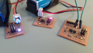
During the electronic design assignment I made the led and button redesign, but I also created a mashup of the rgb echo board and the phototransistor board. They both use the ATtiny45 microcontroller, which made it easier to remix them. At the time, I just programmed it with the same .c code to activate the rgb led and confirm that the board works. (Or at least that part of it does.
Fab ISP assignmentElectronics design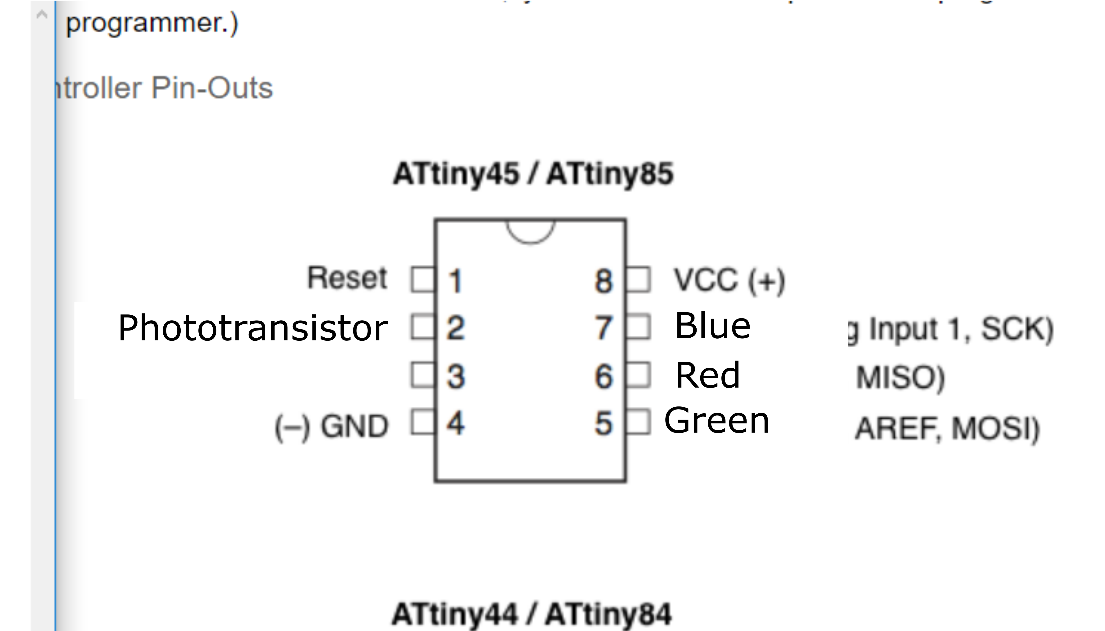
Programming ATtiny through Arduino IDE
As a novice, I felt like I could just jump into the arduino IDE to program. I completed about half the example projects in my kit, then created a mashup of two example codes (one for an rgb led that cycles through colors and another for a led controlled by variable input)
The more difficult part would be to interface the Arduino IDE with my FabISP. Or... so I thought. I followed this amazing step by step guide, which made the whole thing way less difficult than I ever imagined.
To make it easier for myself to understand which pins I needed to refer to in my code, I used my Eagle schematic and the reference in the guide below and mapped out the pins.
Arduino for attiny guide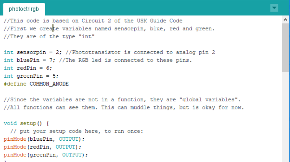
Combining code
I wrote and verified, rewrote and reverified until I had a code which appeared to do what I wanted it to do, which is to respond to light by turning purple, or darkness by cycling through all the colors. In my final project I want the led to be off when the light levels are high, but for now, a positive output tells me more than a negative one. Changing the code to turn the led off rather than purple should be a simple matter later on.
My Arduino code
Jubilations and confusion
At first, my computer couldn't talk to my programmer. This was because I didn't have the driver installed on the computer. I downloaded Zadig, and it helped me install the required driver.
Once I had the driver, I could load up my code without any errors.
...
For some reason it just blinks blue. I need to go over the code again. I assumed that the base code should work, and tried using the rgb code from Circuit 03 (changing the pins to match my board) This also just blinks blue, so perhaps it's the underlying code I need to rewrite. Another possibility is that my pin map is wrong for some reason.
Note: Weeks later I found the solution. See the week on output devices for more info.
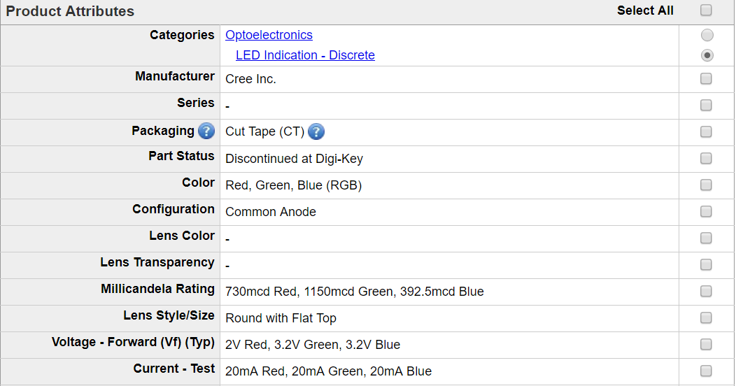
Common Anode
It appears that when working with a common anode, like I am, you have to enter the code "in reverse" as in, 255 is low and 0 is high. This might be part of the reason why the code did not work. It is also possible that I burned my bootloader wrong. While attempting to fix my issue, I misunderstood Bas's instructions and burned my bootloader two more times with different settings. My little circuit chip got all con"fused" and is now fried.
In the Arduino IDE, I got the error code "Initialization failed, rc=-1" This means that the IDE can talk to the programmer but not the programee. This was the first sign that my board was damaged, and while there are ways to fix this sort of issue, they're a bit out of my league.
Code for common anode rgb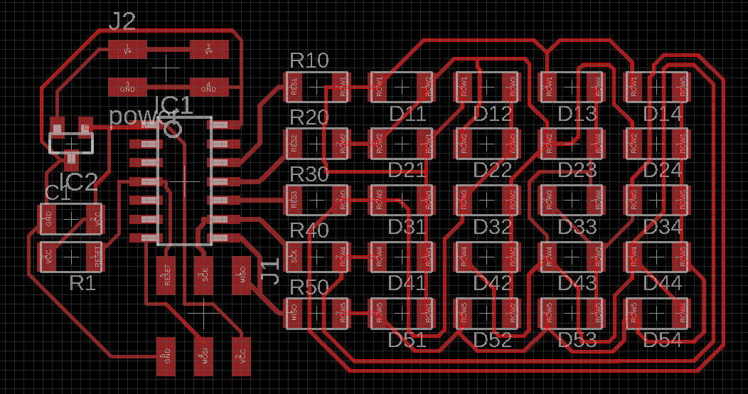
Time Management failure
I did not have time to mill a new board or fix my fried board. This may in part be because I began redrawing the LED array. My reasoning for starting this project is that RGB LEDs are more difficult to work with than single color LEDs. Therefore, it makes sense to begin with regular LEDs, with the option of expanding to RGB LEDs at a later time.
Some people think that electronics design is not a creative process, but I disagree. I got into a good flow trying to eliminate all the 0 ohm resistors, and lost track of time. I succeeded, but by the time I "came up for air" it was 1 am and I hadn't had time to do much else.
.brd Nojumparray.sch Nojumparray