Making ATtiny45 talk to a computer
the Tiny and the Titan converse at last.
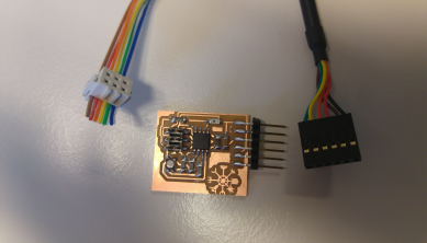
FTDI
There are a lot of different connectors you can put on a chip, and they all serve different purposes. In my first iteration, I naively thought that the phototransistor would just work like it should right away, and that I could program the output from the transistor to my rgb led without needing the computer to read the data.
Once I discovered how wrong I was, I decided to include an FTDI header on my board, which enables the chip to talk to the computer in a limited way. You still need your FabTinyISP to tell the chip what the computer wants it to do, but then the computer can listen to data on a specific line that leads directly to the chip.
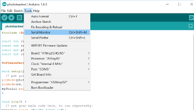
Arduino IDE Serial Monitor
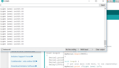
This week, I discovered that the Arduino IDE comes with a built in "Serial Monitor" which can listen to bytes from the chip and translate them to human readable data. To access this monitor, you click "Tools" and select "Serial Monitor". This opens a separate window, which doesn't do anything just yet. First, you need to send the right code to your chip so it knows what kind of data to transmit along the channel.
Serial vs. SoftwareSerial
I hit a bit of a bump in the road when I looked at guides on how to make the phototransistor work. Most of the guides said to use a function called "serial", but this returned nothing but error codes for me. As far as I can understand, ATtiny45 doesn't have built in serial ports, which is why they must be simulated with software. In order for that to work, you must include a special library called SoftwareSerial.h.
Once the library is included, you specify a serial, and use a slightly different setup for the code. I included an example of this code below.Unfortunately, this code only returned a max value feedback for me. It would only vary by a single digit when transitioning from a strong lightsource to complete darkness.
Misreading guides
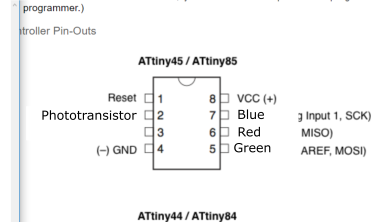
When we began programming with arduino we needed to consult pin maps to know which pins to program and how. I did so, thoroughly. Unfortunately, I read it "upside down". I thought the old names were pin0-pin5 and that the new ones were simply numbered 1-8. It is, of course, the opposite. Frosti prompted me to doublecheck my work, and since it only takes a second to change the pin numbers, moments later I had a functioning phototransistor/rgb led combo in my hands!
This image shows my misunderstanding.
High-low tech guideFine-tuning
After some fine-tuning of the "switch" state, i.e. at what light level the light should turn on, I now have a chip which reliably turns on in the dark and off in the light. Occasionally, the shadow from my ISP cable will turn it on, but that should not be an issue with the final version, as the cable is only there for programming purposes.
A step ladder
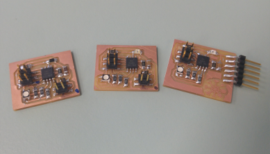
The board I was using now is a modified version of the one I created for the embedded programming week. Here is a link to a zip folder containing the arduino code and the schematic and board files. The second link will take you to previous relevant projects
Relevant filesPrevious projects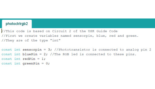
About the code
The first part of the code designates some integers and pins. Here, we see which pins on the microcontroller correspond to which pins on the RGB LED. I have since learned that since these pins will not change, I could also use #define to define those pins, which would save some memory. However, when I wrote this code, I did not know that, and just did what seemed to work.
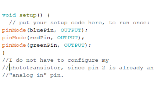
Void Setup
In the setup, I designate whether the pins I configured above are inputs or outputs. This void setup is particularly simple, but it does the job.
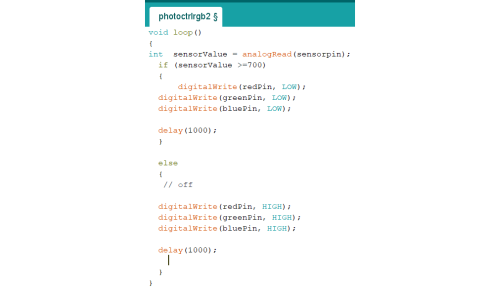
Void loop
The plain void loop is an if statement, which states that if the value received from the phototransistor is equal to or more than 700, it should turn the LED on. In this case, it will be white, since all LEDs are set to LOW. Else, it is meant to turn the LED off my setting all the pins to HIGH. It is counterintuitive, but this is because they've got a common anode, so the pins must be HIGH to be off, and LOW to be on. In either case, the status is meant to wait 1 second before testing the light level again.
If I replace the "All LOW" statement with a "showSpectrum()" the code would cause the LED to run through the showSpectrum() loop before testing the phototransistor signal again, but this turned out to be inconvenient for testing and showcasing that the LED responds to the phototransistor.
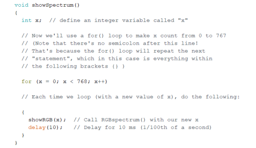
showSpectrum()
Showspectrum introduces the new integer "x" and sets a value for x which is then sent to showRGB() which sets a specific color value for the LED to display. It then waits 10 ms before sending the next value for x, and so on until every value has been sent and displayed, at which point it starts over.
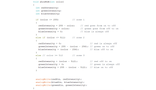
showRGB()
showRGB() receives the value for x from showSpectrum and uses it to set the numerical value of the red, green and blue pins. It runs through the colors, but since I got the code from another project, I now see that it seems to be "Upside down." In fact, 0 ought to correspond to on, and 255 to off, which explains why I never found the color gradient to be as pretty as it ought to be. Instead of one color being off all the time while the other to cycle to be even before switching statuses, one was always on while the other two were switching.
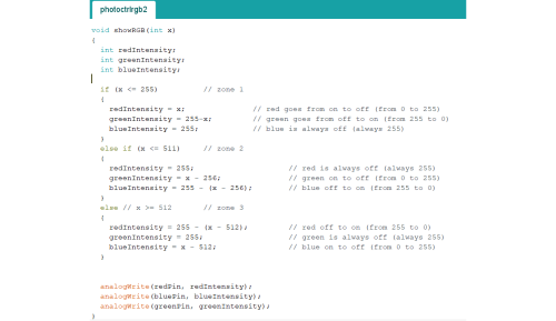
showRGB() revised
I changed the formulas so that now the green LED will cycle from being off to fully on, to fully off again, after which it stays off for a while. Red will cycle from being fully on, to off, then it stays off for a while before going back on. Blue will stay off for a while, then go fully on before going back off again. This means that the colors displayed should start at red, through yellow to green, through cyan to blue, through magenta to red again.
I have not had time to test this code, but am quite confident that it will work. I include it below for completion's sake.
Revised code