Making sure the machine doesn't go off the rails.
Limiting and Homing
Limit and homing switches
As we have come to understand through these last few weeks, one of the most essential parts of digital fabrication is that the machine knows where the end effector is and where it needs to be. To provide the machine with this information we use homing switches. When we zero an axis, we tell the stepper motors where the furthest point of travel in one direction is. If it cannot physically travel further in that direction, it has reached the absolute zero point. I decided to make little buttons that could be attached to the axes of the machine, so that such zeroing could be performed. I also included limit switches. Limit switches are much like homing switches, except that they only stop the end effector from travelling further in a specific direction, and are not used for zeroing an axis. For example, the y axis might have a homing switch at the far back of the machine, and a limit switch at the front. The z axis has a homing switch at the very top position and a limit switch at the bottom position, and the x axis has a homing switch at the far left and a limit switch at the far right. Additionally, I made but did not connect two optional switches which may be connected to the "a axis". These switches are often used as emergency stop switches in case something goes wrong.
Designing a limit switch
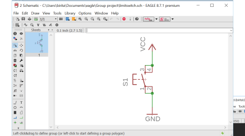
The limit switch is an incredibly simple circuit. I only has a button, and will be analog wired to send a signal when the button is pushed, and not send a signal when it is left alone. Still, it's good to have it all se up, especially because the board will display the orientation of the button for soldering.
Layout of a limit switch
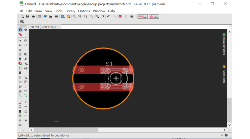
I wanted the switches to be more aesthetically pleasing than a square piece of copper. I also decided to make holes and rivet them to make it easier to attach the wires securely. I therefore drew my circuit a bit differently than normal, with big lines of copper for the traces/pads and a circle as my dimension.
Eagle files for the limit switch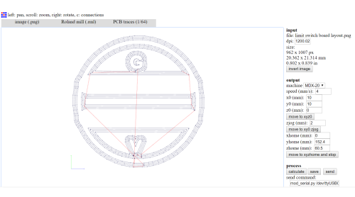
Fabmodules and milling
I exported the board as three 1500dpi, monochromatoc PNGs. I altered the interior image in Gimp by filling it in with white. I then milled the traces as normal, with a 1/64" bit and 0.2 depth. Second, I milled the holes with a 1/32" bit and .6 depth, and finally I milled the outline with the same bit and depth as the holes. I didn't know back then that milling the holes and outline in one file works just fine, or that Fabmodules will design the path so that holes are drilled first, and then outlines.
First, I milled one, to make sure the design works. I then milledtwo batches of four at once, to move things along. I soldered them all at once, like a one-woman production line.
cut files for single switch cut files for four switches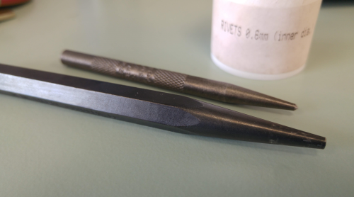
Riveting and attaching wires
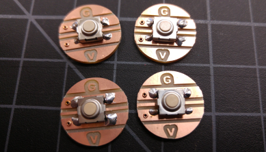
These switches use two 0.6 mm rivets each. I used a two small punches, one pointed and one rounded to hammer my rivets into place, then soldered them thoroughly. The best way I've found is to place the iron directly on the rivet, then place the solder at the edge of the rivet, making sure to touch the trace as well. With the correct amount of solder, it should flow all around the rivet and into it as well as along the trace a bit. With this method, soldering each rivet only takes about 2 seconds. I made sure to attach wires with different colors for each switch, to make it easier to know which was which switch after pulling the wires through the various holes. To make it easier to attach them to the Tiny G ports.
Because I had rivetted the holes, attaching the wires was exceptionally easy. I simply degloved about 1cm of strands on each wire, spun it up, slipped it up through the hole and soldered it in place.
Placing switches
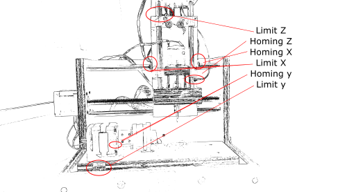
The switches are placed at the top and bottom of the z axis moving piece, the front and back of the y moving plane and on either side of the x moving part. The switches can just be seen on this picture, except for the back y-axis switch, as it is hidden behind the 4th axis addition.
Connecting switches to TinyG
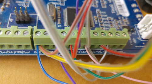
I ran the wires as neatly as possible to the back of the machine where our Tiny G was attached. There, I carefully connected each wire to its corresponding place on the Tiny G. It is a bit difficult to see, but underneath the wires, there are plug ins for each limit and homing switch, as well as several grounding points. Each switch must be connected to its connector and to ground. The different colors on all the switches came in very handy at this point so that they were all connected to their proper places. The connectors for Axis A can be used for emergency off buttons, as this axis generally does not have homing or limit switches enabled.
Homing and G28
G28 is the g code that deals with the homing system. By typing G.28.2 X0 Y0 Z0 we tell the machine to go to absolute zero on these axes. It will first go to zero on Z, to ensure that the tool is lifted off any work surface that may be in the machine. For each axis, the sequence is as follows: if either of the limits are triggered, the machine will first back off from the switch. The machine will travel at medium speed toward the homin switch and stop immediately once the switch is reached. It should then perform a latch move, which means that it backs off the switch until it is no longer triggered, then stops. If you have a "zero backoff", it will then move the designated mm away from the latch position. It will then flag that axis as "homed" and move on to the next axis until all have been homed.
Guide on homing and limit switch setupSoft limits
If we would have had time, we could have then enabled soft limits as well. To enable soft limits, one first needs to home the machine. Once all axes are homed, you can enable soft limits, by telling the machine how far it can travel in the other direction. It will then treat these "invisible" limits as if they were really there.
Unfortunately, this is where we ran out of time, but it is certainly interesting that it would be possible for owners of machines that do not have homing or limit switches to install and configure such switches at relatively low cost.
The rest of the group
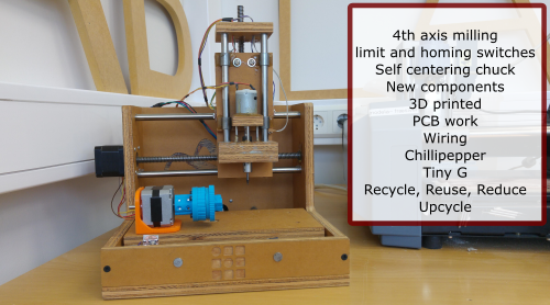
The rest of the group worked on making a self-centering chuck, fastenings for the base platform, working with toolpaths and coding with Chillipepper. The machine worked in the end, at least as far as that we could turn on the 4th axis and mill a path into a crayon, but the chuck was too weak to hold such a long object on it's own, and it would have been better to have something holding the piece on the other side. However, this was an interesting way to reuse something that already existed in our lab.