Together with the Mechanical Design week, this week's task was to build a three axis machine. This week, the focus was on automating the machine that we built before, which was a sky-cam like ring with a light sensor (more details on our group page). My contribution was the realization of a control algorithm that randomly samples cartesian coordinates inside the frame, converts these coordinates to a number of steps each motor has to move, and finally moves the motors accordingly. I did this by using the geometry of our frame to figure out the required change of length of each rope. To troubleshoot the algorithm, I also implemented an interactive control system.
Making use of Geometry
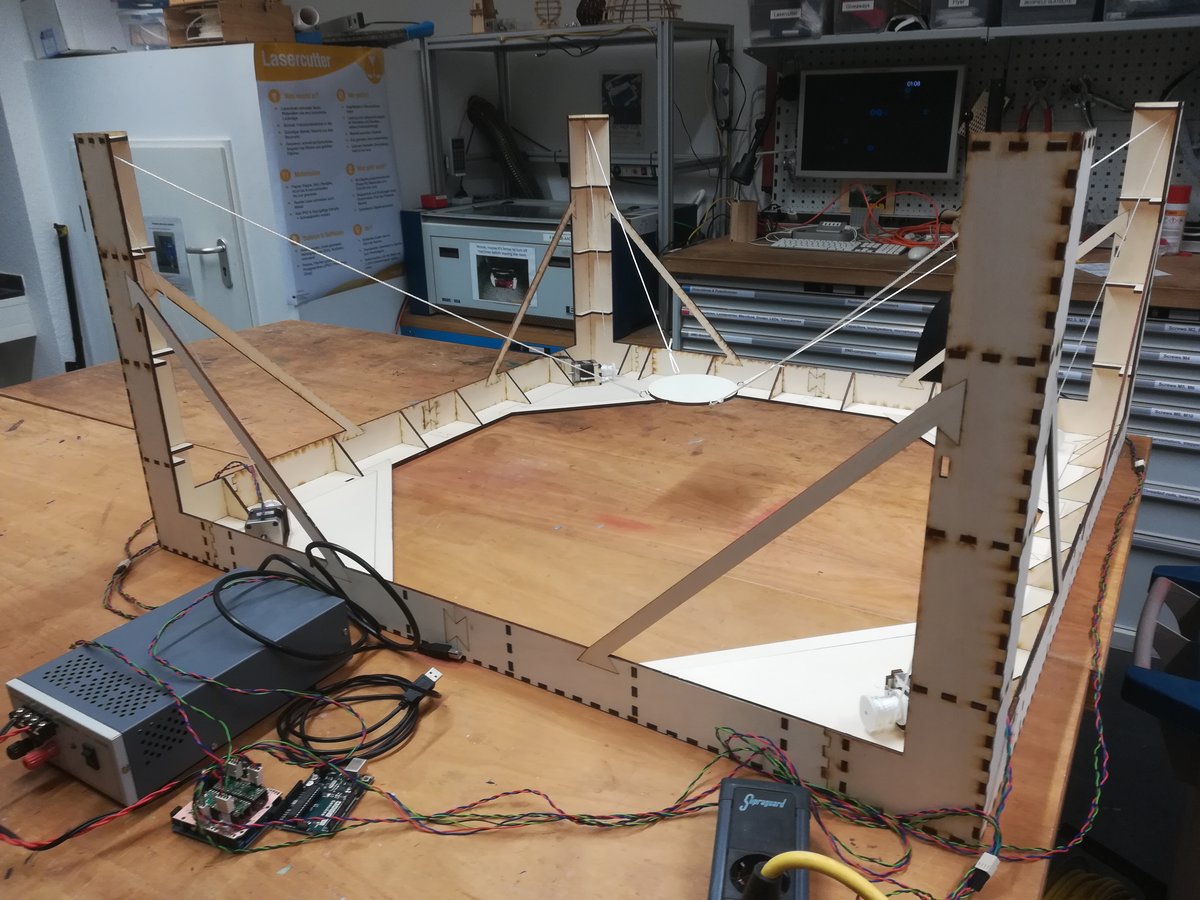
Our goal is to write the lengths of the four wires holding the sensor as a function of the sensors cartesian coordinates. The frame is a cuboid with dimensions , , and , for width, length, and height.
The four rope hinges are mounted at the pole tops at the corners of the frame. The positions of these hinges are named and , in clockwise order. The length of the corresponding rope is named , respectively. Putting the origin of our coordinate system in the middle of the frame at zero height gives them the coordinates
Now, let's name the midpoint of our sensor ring , and note that the mounting holes have a displacement of along the coordinate x- and y-axis, compared to the midpoint . Then, assuming wires of zero thickness and a weight of the sensor large enough to pull the wires straight, we have
This is exactly what we wanted: the length of wire as a function of the midpoint coordinates . For example, the length of the wire at is .
Given the length of the wire at the starting point, we can determine the change of length for each wire, . To relate with the number of steps needed to achieve this change, we calculate
where is the radius of the winding attached to the motor. Again, we are assuming an infinitely thin wire.
Now, we can implement the control algorithm.
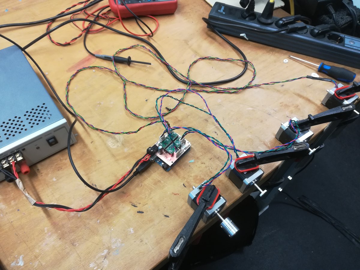
Controlling stepper motors
The A4988 drivers that we used make it really easy to control stepper motors; all that's needed is one pin to generate pulses to the drivers' step pin, and one pin to control the direction the motor is turning by setting the drivers dir pin to logic high or to logic low. In order to improve start and setting behavior, we used a linear acceleration and deceleration curve.