This page details my journey towards a working final project. For a more concise description on how to build it, visit the actual project page.
Proposal
Filming while moving is hard, because often one cannot suitably stabilize the camera without proper equipment. I would like to build a preferably small active 3-axis gimbal that can be used with the Raspberry Pi Zero and the corresponding camera. The pictures of the camera should be streamed to a mobile device, for example a smart phone or a laptop. The gimbal could be attached to a drone and be steered from the mobile device, providing stabilized aerial footage. As a possible further improvement, one could try to integrate the gimbal with a VR headset, which would allow to change the camera view via head movement. The headset could simply consist of a 3D-printed smartphone holder with lenses.
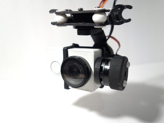
This is an example of a 3D printed gimbal (photo and design taken from here.). The design consists of 23 printed parts and 3 brushless DC motors; it is small and lightweight. This example shows that it is indeed possible to create something as fragile as a gimbal with 3D printers, so I'm positive that I will be able to make my own gimbal for the pi zero.
First Considerations & Milestones
Since I wrote the above paragraphs, I conducted some research on DIY gimbals. As in the above project, I decided to use brushless DC (BLDC) motors (in particular, these motors). BLDCs can be made very small; usually, they have a full 360° operating range and can be turned smoothly, which is very important to operate a gimbal. Since the motors cannot provide a lot of torque (and heat up quite fast), the frame and camera need to be as balanced as possible.
Based on the above project, I identified the following milestones that I need to achieve:
- operate a suitable sensor to measure orientation
- find a circuit to control a BLDC
- control a brushless DC motor
- wire up three BLDCs + their controllers and operate them together
- design and make a case for the pi zero + camera
- design and print a balanced frame fitting three motors, their controller(s), and the camera case
- fit everything together
- optimize the stabilization capabilities (i.e. firmware) on the go
- connect a battery to power the pi + gimbal
I will need at least the following things to create this project:
- three BLDC motors
- corresponding controllers
- a couple of screws
- PLA to print the frame + case
- a pi zero
- a camera for the pi zero
- at least one, potentially up to three orientation sensors
Talking with the MPU 9250
Originally, I wanted to use the MPU9250 as orientation sensor. However, it was not available anymore, so in the end, I used its successor, the ICM20948. The following paragraphs are about communication with an MPU9250 on a breakout board. For my actual final project, I used an ICM20948 on my own board.
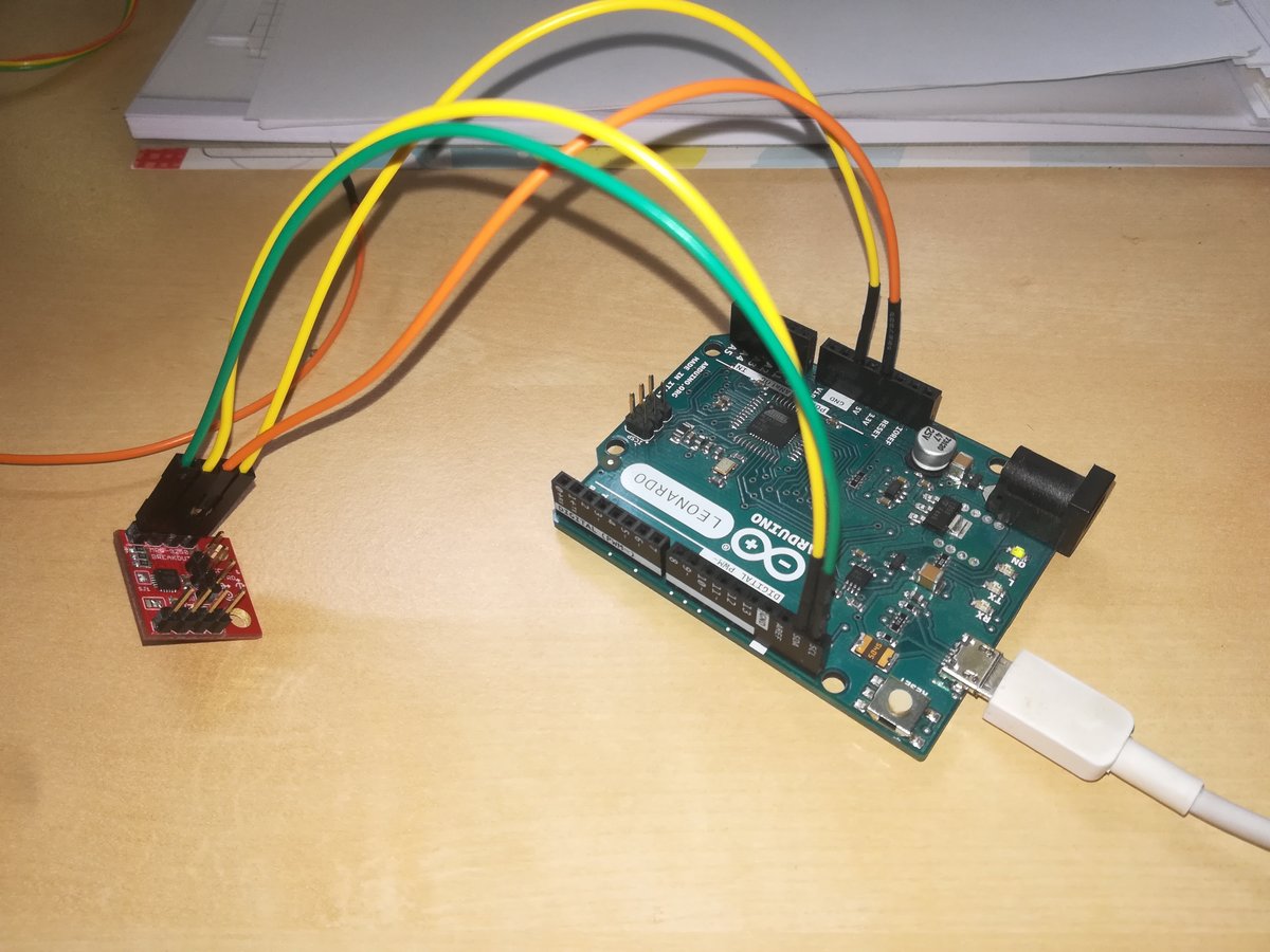
I wrote a little C++ library to communicate with the MPU 9250, since the available libraries (for various Arduinos) are too large to fit into the flash of ATTinies. Communication is done via I2C. The MPU9250 runs at 3.3V, so be careful not to destroy it when trying to connect it to an Arduino. In fact, I could not read the registers when connecting it to the I2C port of an Arduino while powered with 3.3V; I'm not sure why.
However, while I am able to communicate via i2c and read sensor values from the MPU, the readings are not yet suitable for use in my gimbal system, because they cannot be interpreted as an orientation without further processing; also, they tend to drift. Implementing sensor fusion as a process that uses mathematical methods (such as kalman filtering) to combine the readings of the three sensors would give me the accuracy and precision needed for this project, but it is probably not possible on a single Attiny, because it needs computationally expensive floating point operations.
Talking with the ICM20948
The ICM20948 is the successor of the MPU9250. It has more or less the same architecture, i.e. the same pins and similar pin functionalities, and comparable register functionality, so I can reuse parts of the I2C communication code. However, it operates at 1.8V, so I had to use a level converter between my micro controllers and the sensor to shift levels from 3.3V to 1.8V. I used TXB1014 by Texas Instruments, which is a bidirectional 4-bit level shifter IC, suitable for I2C.
The code sets up the ICM20948 for I2C communication, and periodically reads out sensor values for accelerometer, gyroscope, and magnetometer. The values are combined with a Madgwick filter.
Controlling BLDC motors
Brushless DC motors have three (or some multiple of three) coils which need to be powered in a specific sequence to turn the motor. In particular, I need to generate three sine waves that are 120° phase shifted to each other. This is normally done with an electronic speed control (ESC) circuit. If possible, I would like to build my own instead of buying one, simply because I like to find out if I can.
At first, I tried to simply use three PWM outputs of an Arduino. Although it kind of worked, it did not work very well. For the record, do not drive your motor this way - most likely it will not work anyway.
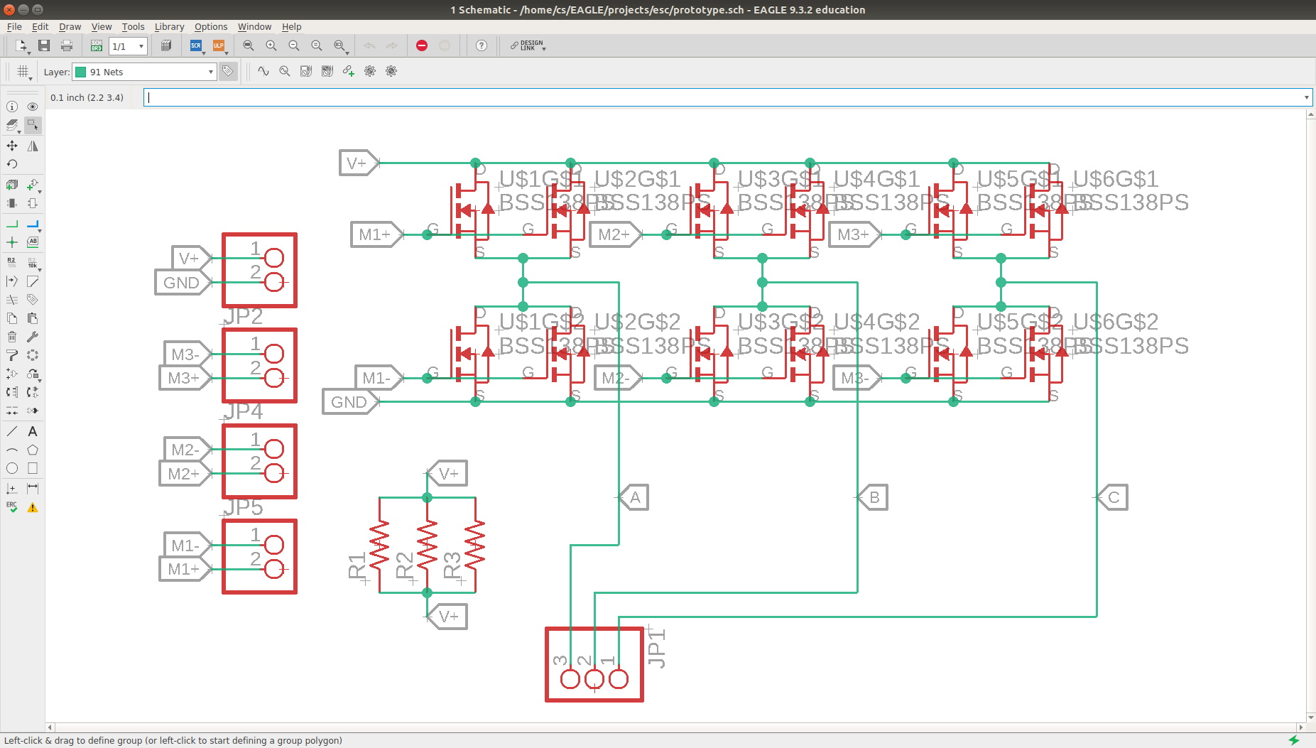
So as a next step, I sketched up a board with three half-H bridges. Because I had only very small MOSFETs which were rated for 350mA, I used two of them in parallel in order to safely handle the 0.5A output by the Arduino. This board has six connections to a MCU, which need to be commutated in the right sequence to drive the motor.
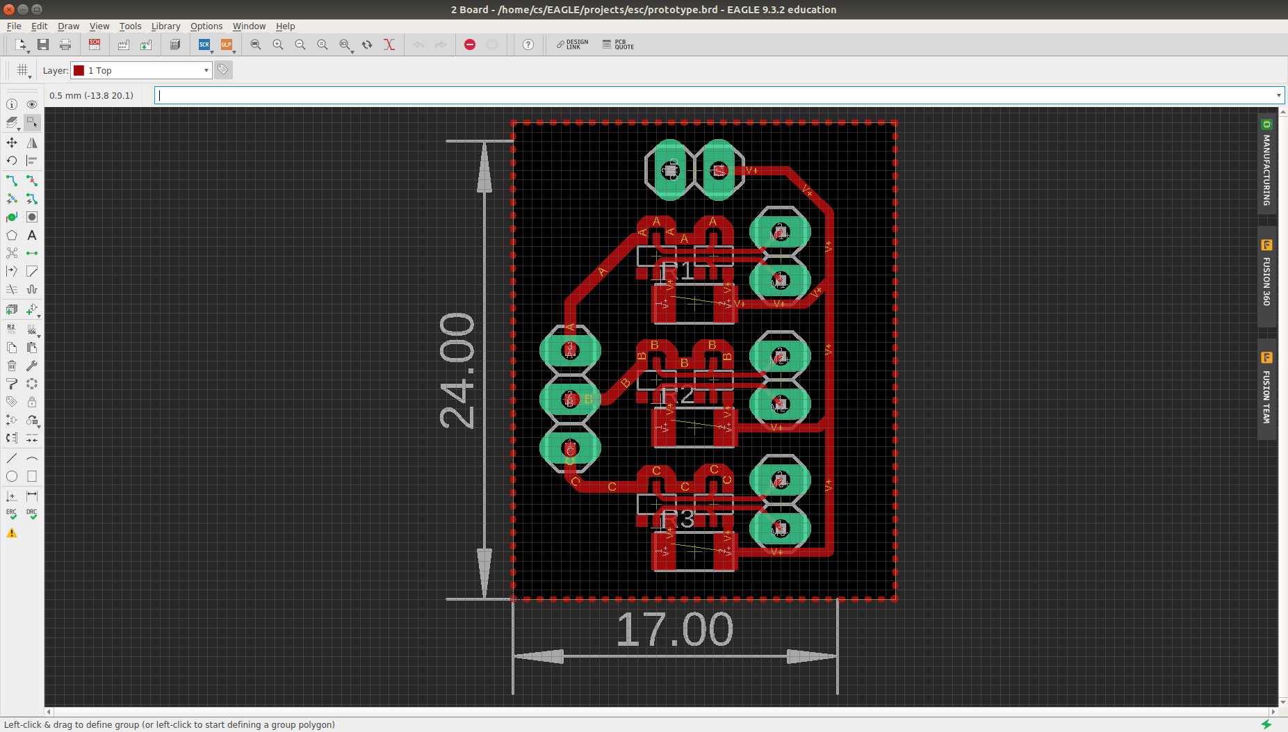
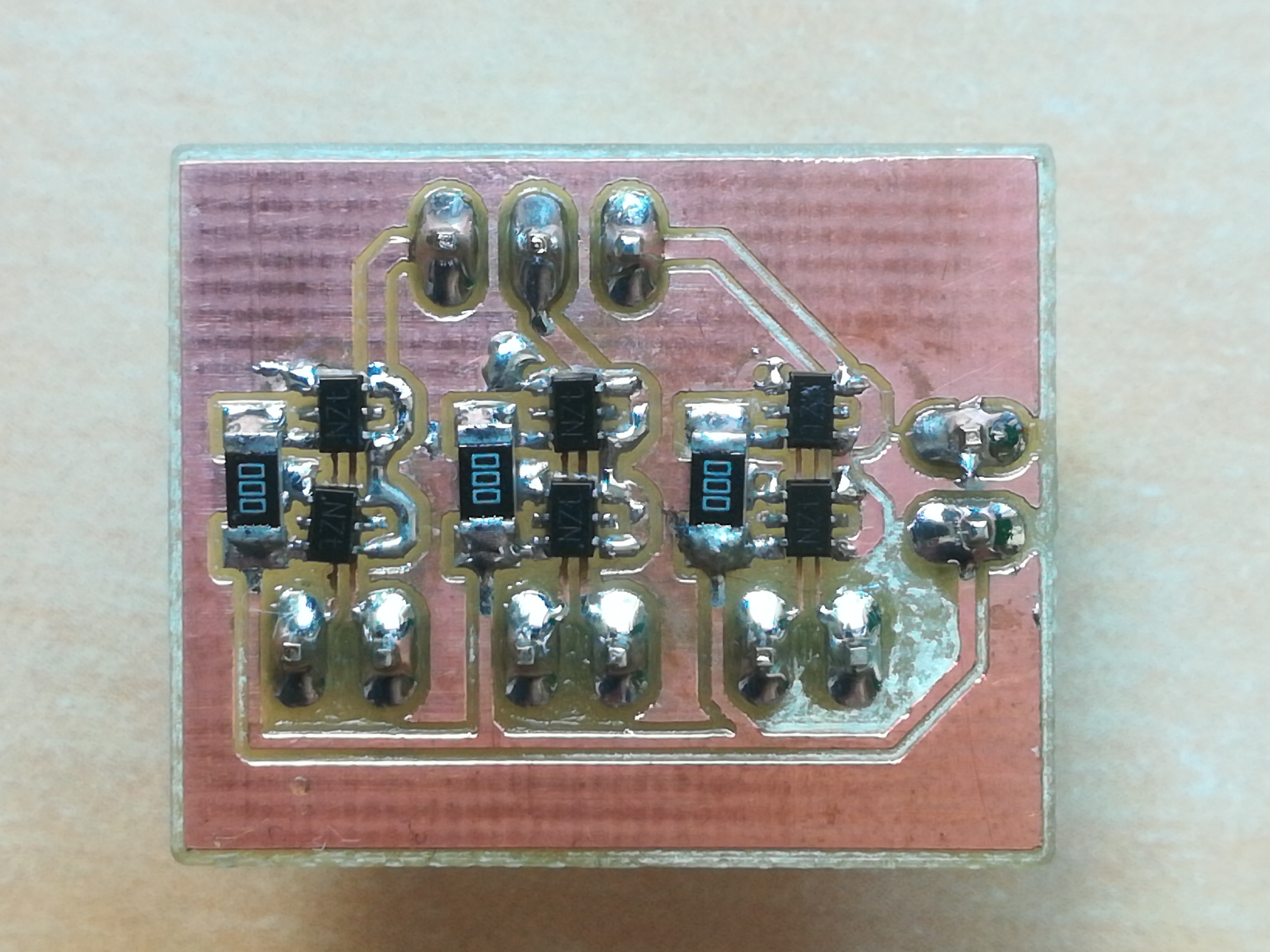
Powered with only 5V and 0.5A, and using only six discrete outputs, I could use a single ATTiny45 to control a single motor. However, their movement is a little jerky, because the coils are powered abruptly, making the rotor jump to the next position. Using PWM signals in a sine waveform instead of discrete signals will probably fix that, but then I need additional hardware.
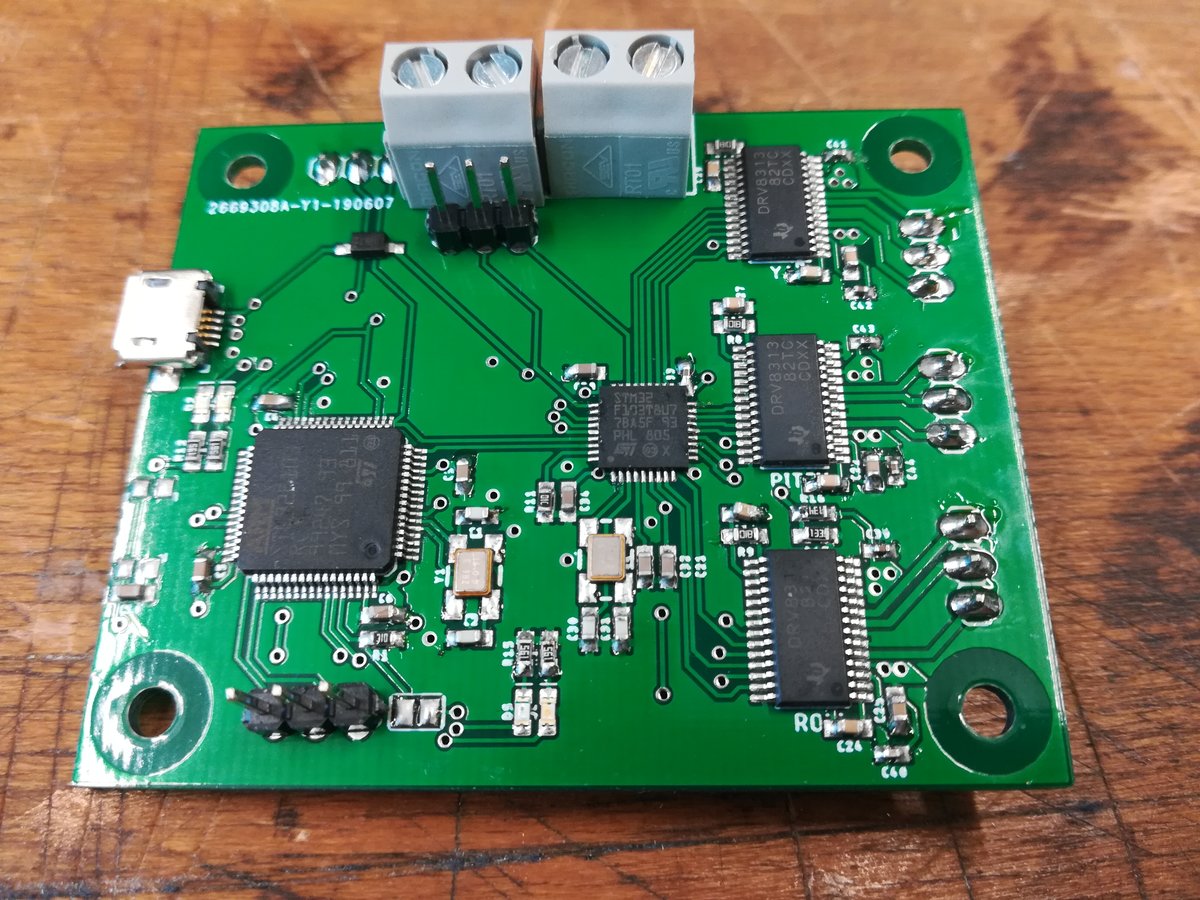
In the end, I chose to use 3-phase BLDC drivers, which are controlled by an STM32. I'm using DRV8313, which are 3-phase brushless DC motor drivers capable of delivering up to 2.5A per winding, which is more than enough for the small gimbal motors I'm using. All three of them (one for each motor) are driven by a single STM32F103T8U6, via sinusoidal motor control. That is, the controller generates three PWM signals such that the average voltage of each signal constitutes a sinus waveform, and the three signals are 120° phase shifted to each other. I'm using PWM signals of 20kHz, and a maximum of 40% duty cycle (at 12V). Limiting the maximum duty cycle prevents overheating of the motors (they heat up very quickly, especially under load, since the resistance of their windings is very low).
Hardware
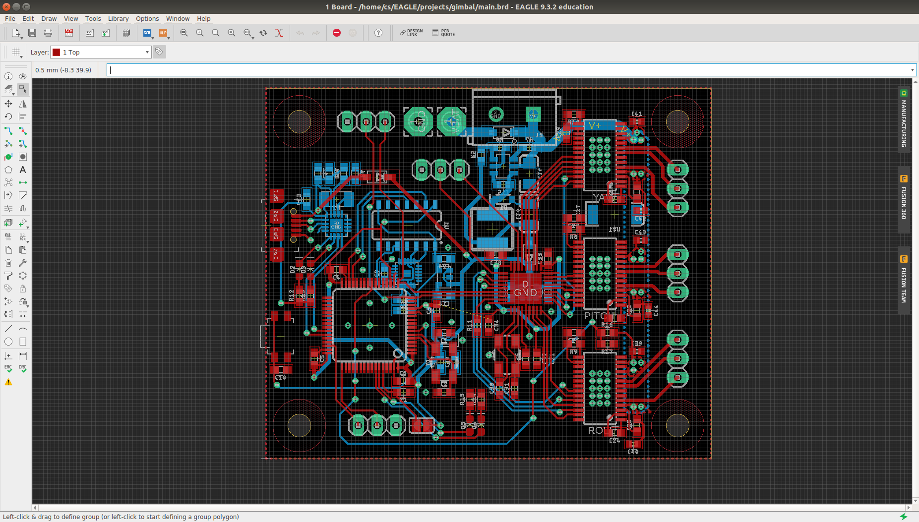
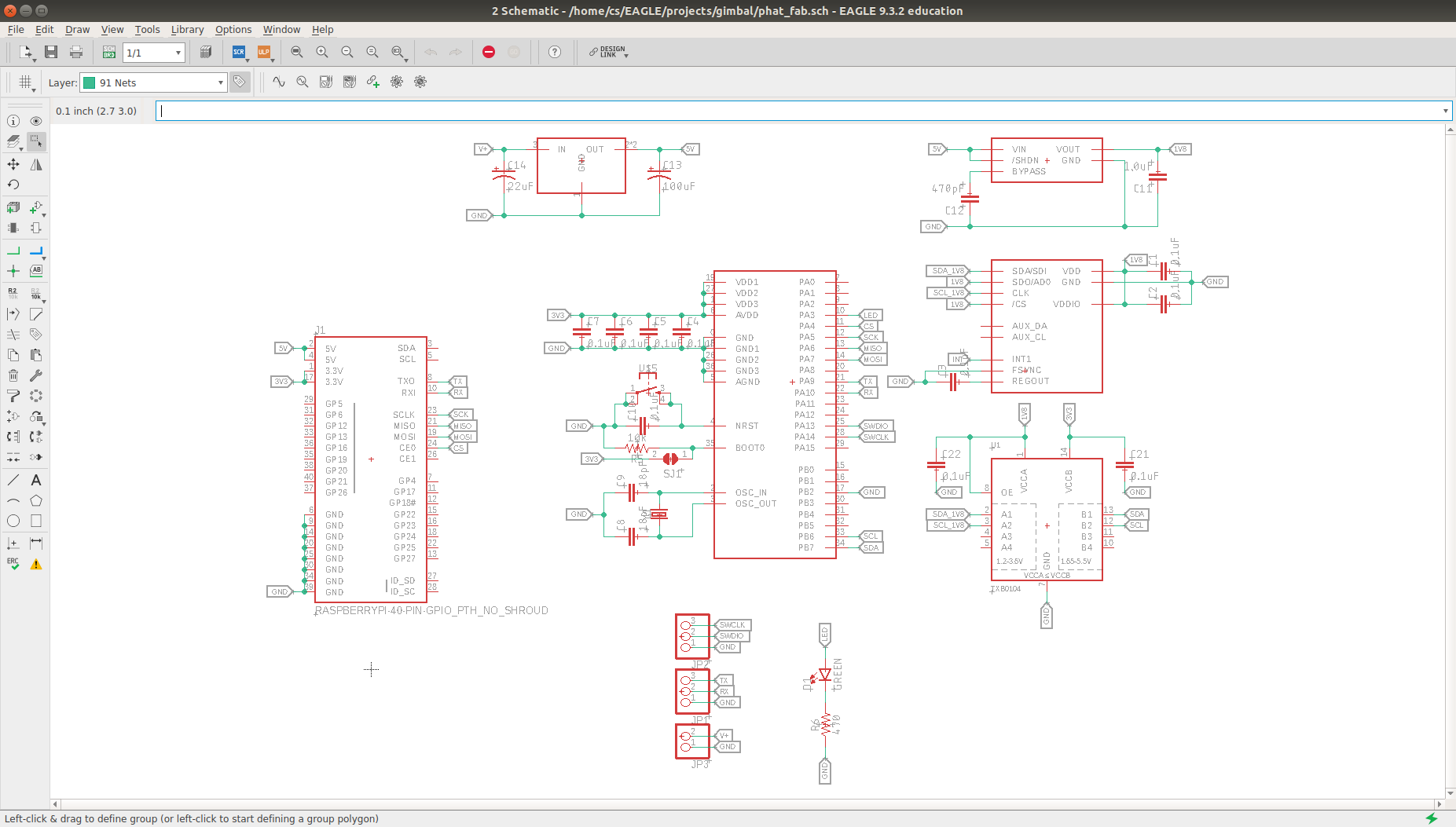
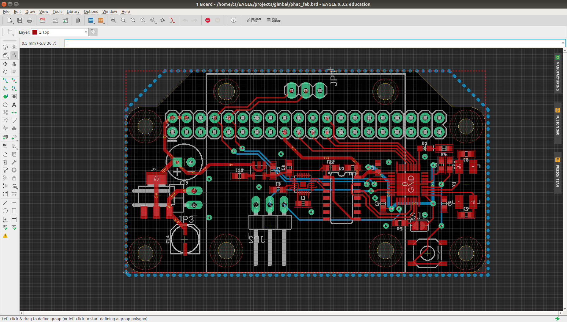
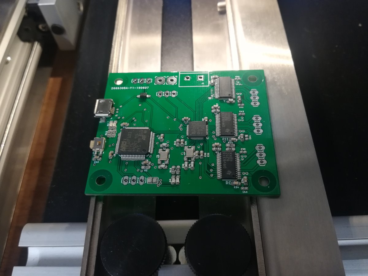
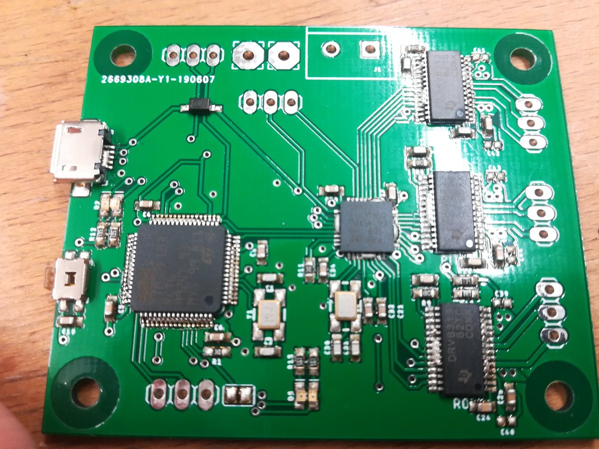
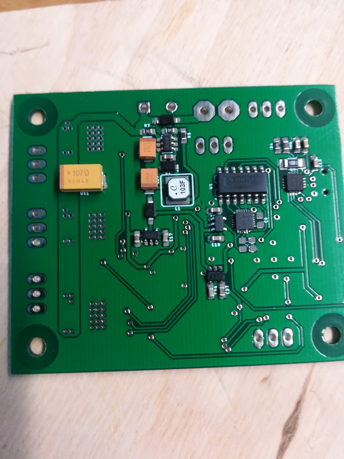
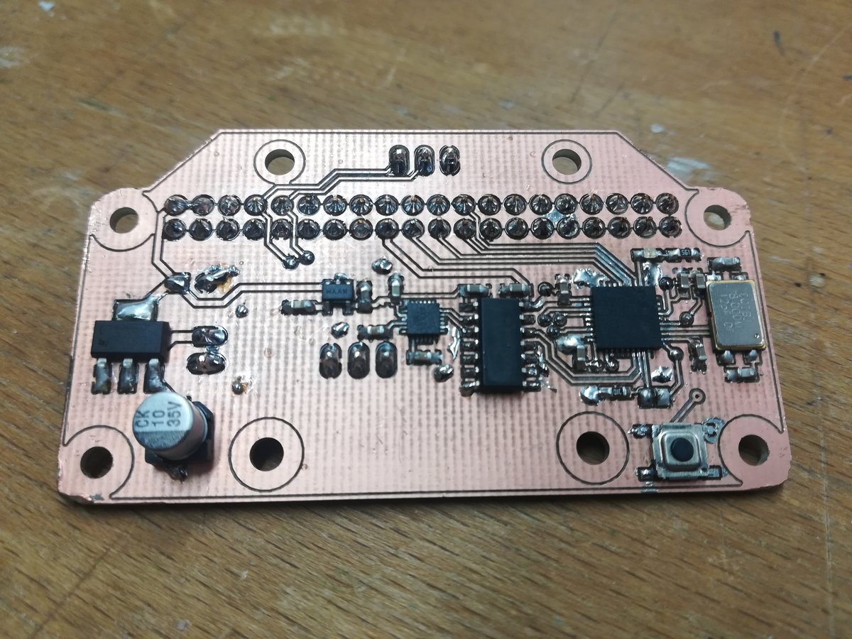
I designed a rather complex main controller board housing an STM32F103RCT6, which is a quite powerful 32-bit microcontroller, a STM32F103T8U7, which is a little less powerful, but still has enough computing power and peripherals to control three 3-phase BLDC drivers, which are also on the board. Additionally, there's an USB-to-UART chip, a couple of status LEDs, an optional second IMU, and electronics to manage 8-16V battery voltage. There are connectors for programming both chips via serial wire, headers to connect the battery and the motors, and pins to connect the main board with the board housing the orientation sensor.
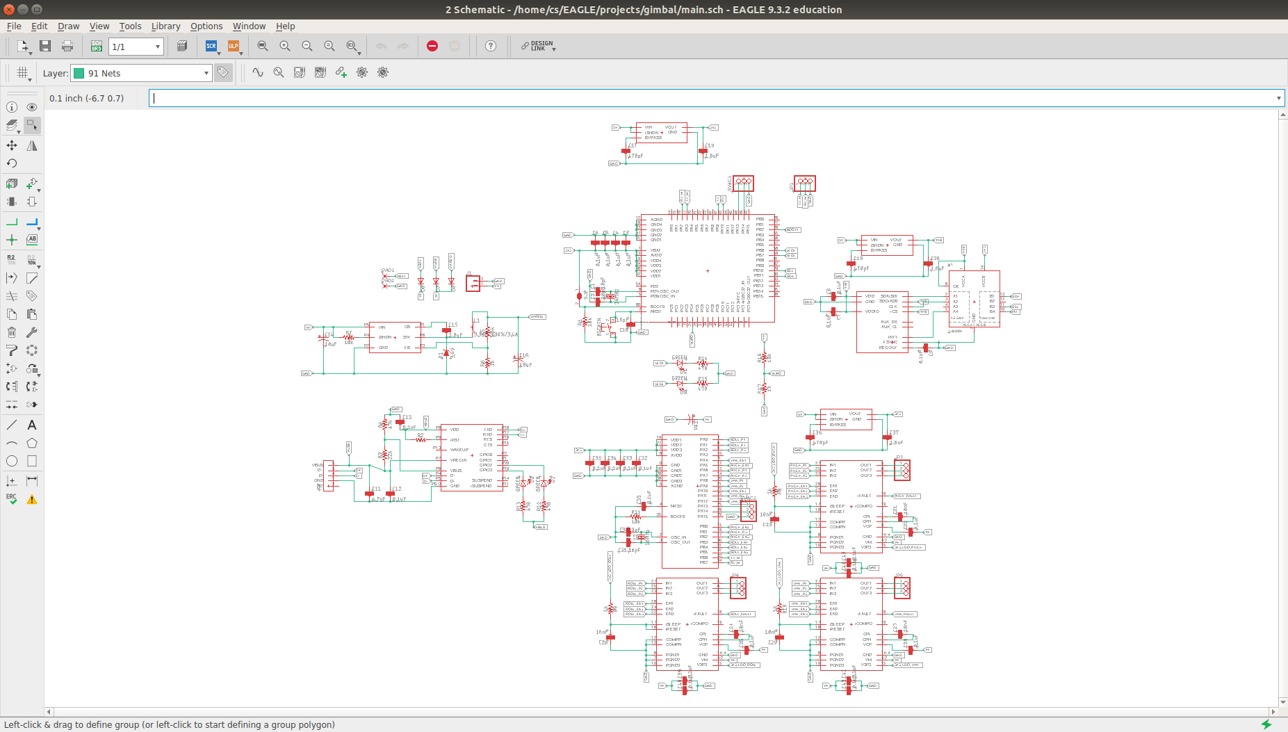
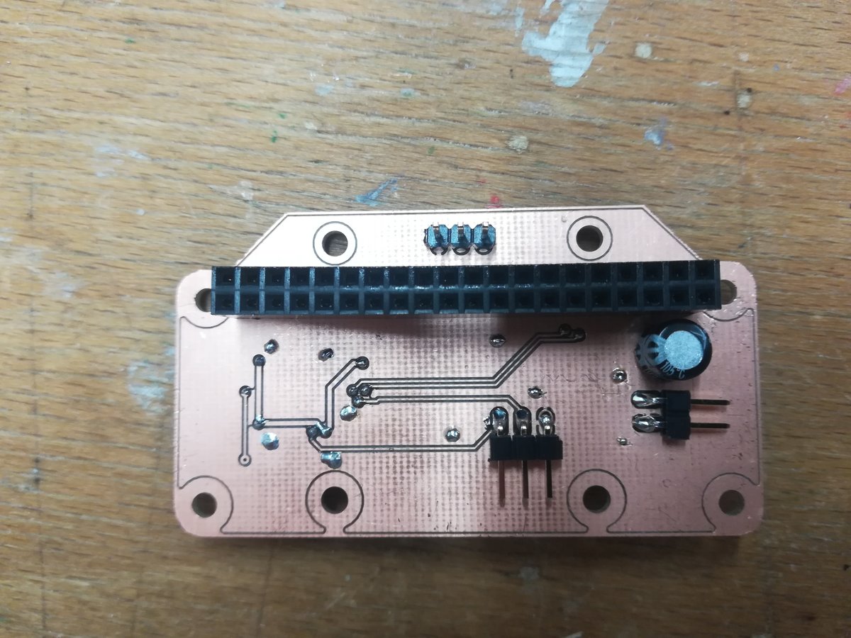
To sense camera orientation, I designed an extension board for the pi which features voltage regulation for the pi, a 9-DOF orientation sensor, and another STM32F103T8U7 which executes the sensor fusion algorithms. The STM on this board can also talk to the pi via SPI on the GPIO header. Just as the chips on the main board, it can be programmed and debugged via serial wire.
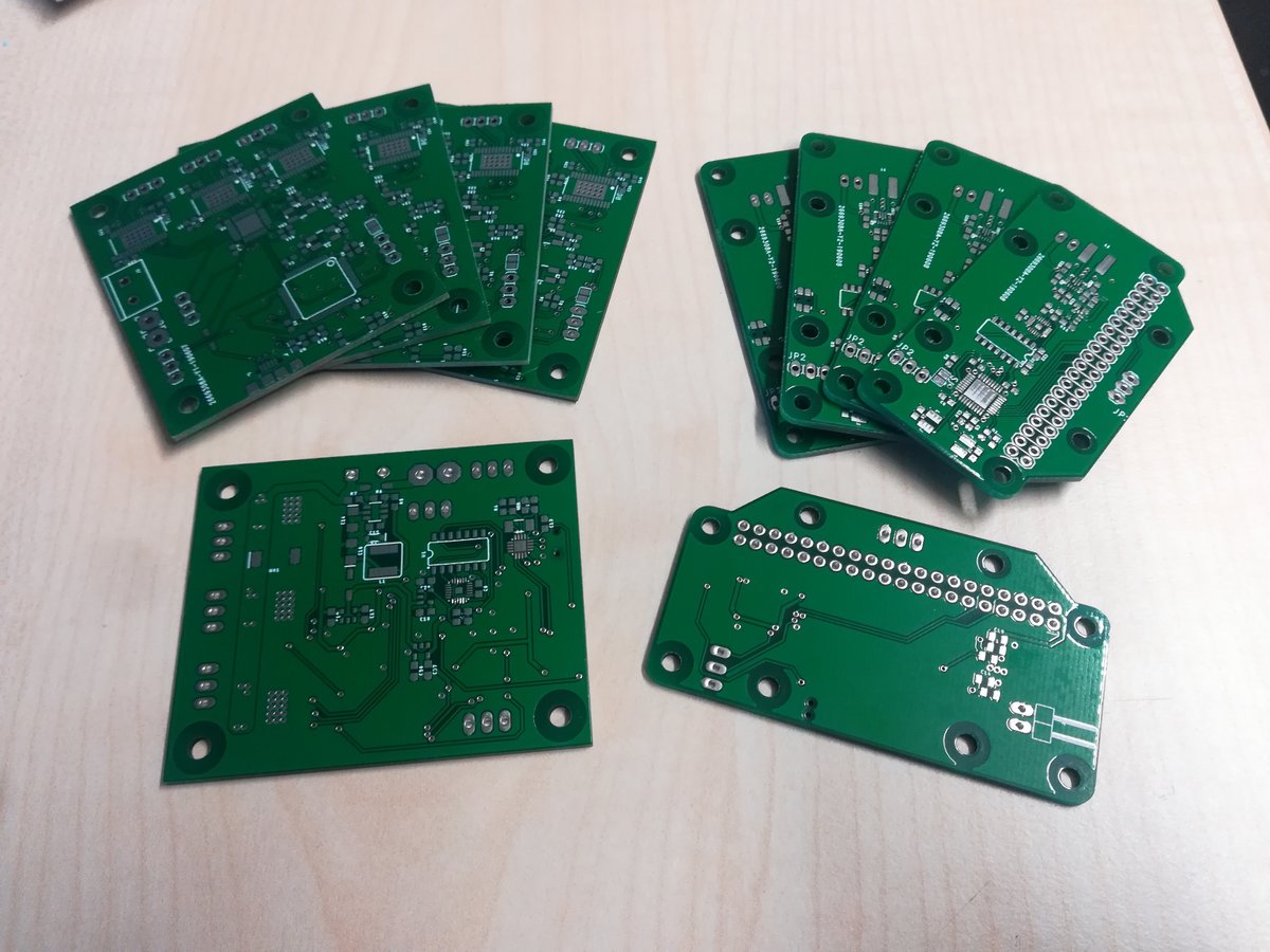
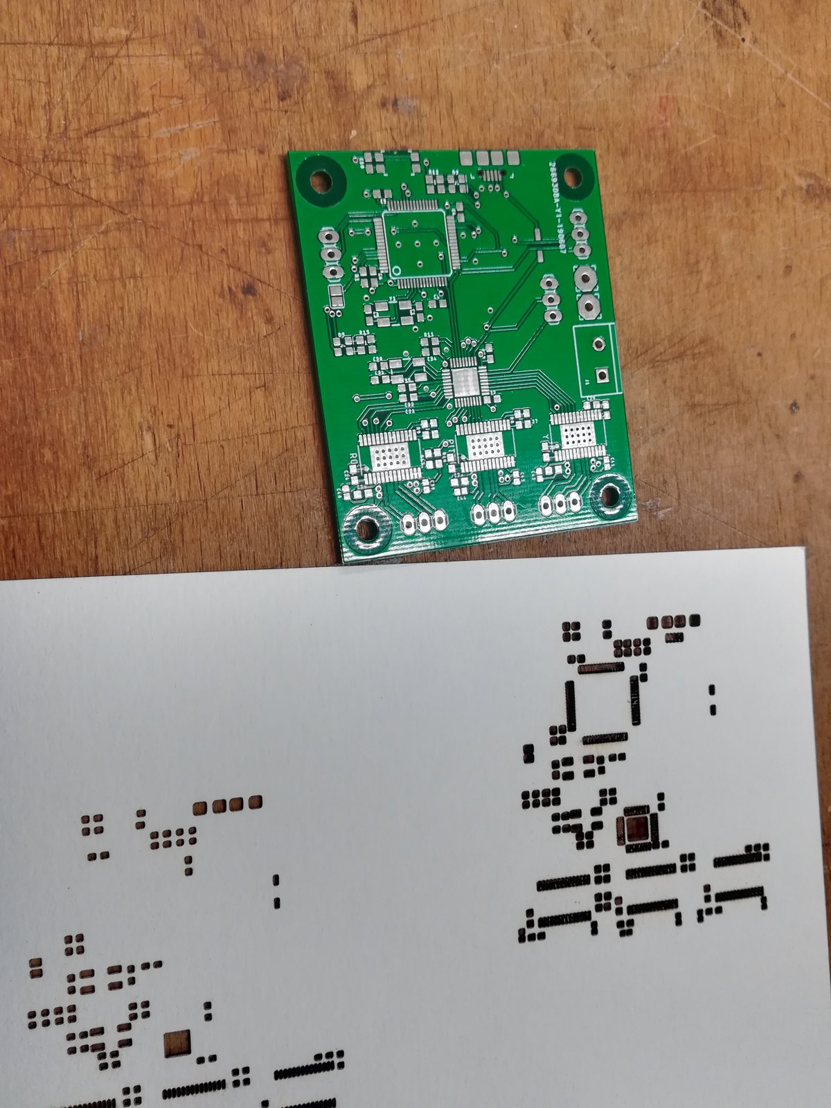
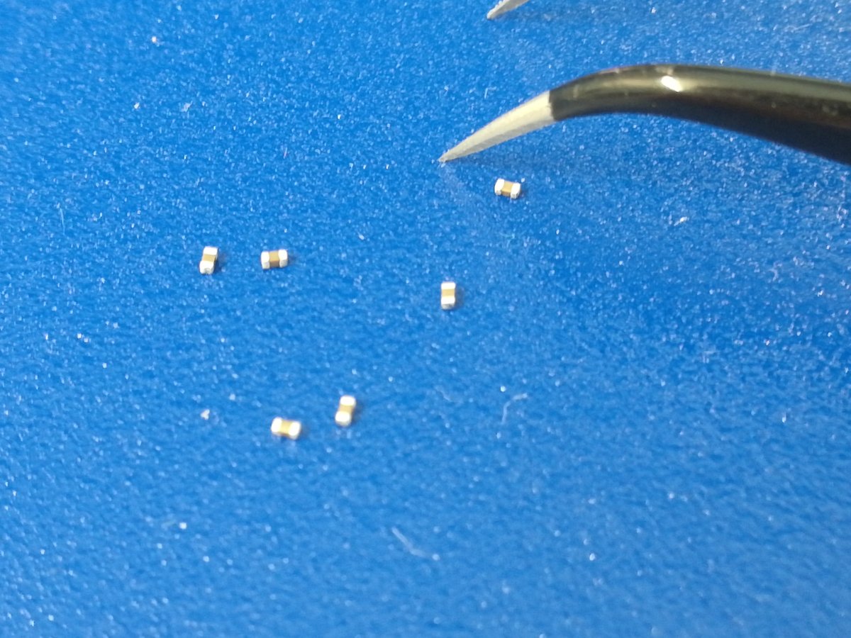
Unfortunately, making the hardware proved to be a major problem, because our PCB mill was not working for most of the time during the weeks before the final presentation. In order to make sure I would be able to present my project in time, I ordered a batch of PCBs from a prototyping service, which also arrived late, but just in time to get a first version to present. However, I had bad luck while soldering the boards (which is not easy, because all of the parts are tiny, and the board is packed with components). The first time I used soldering paste without lead, which did not melt properly, and I had to spend two days trying to fix the board, because I did not have enough components to make a second one (the additional components that I ordered arrived just after the presentations). I managed to somehow fry the motor controller and a couple of pins on the motor drivers, so the first board was not usable.
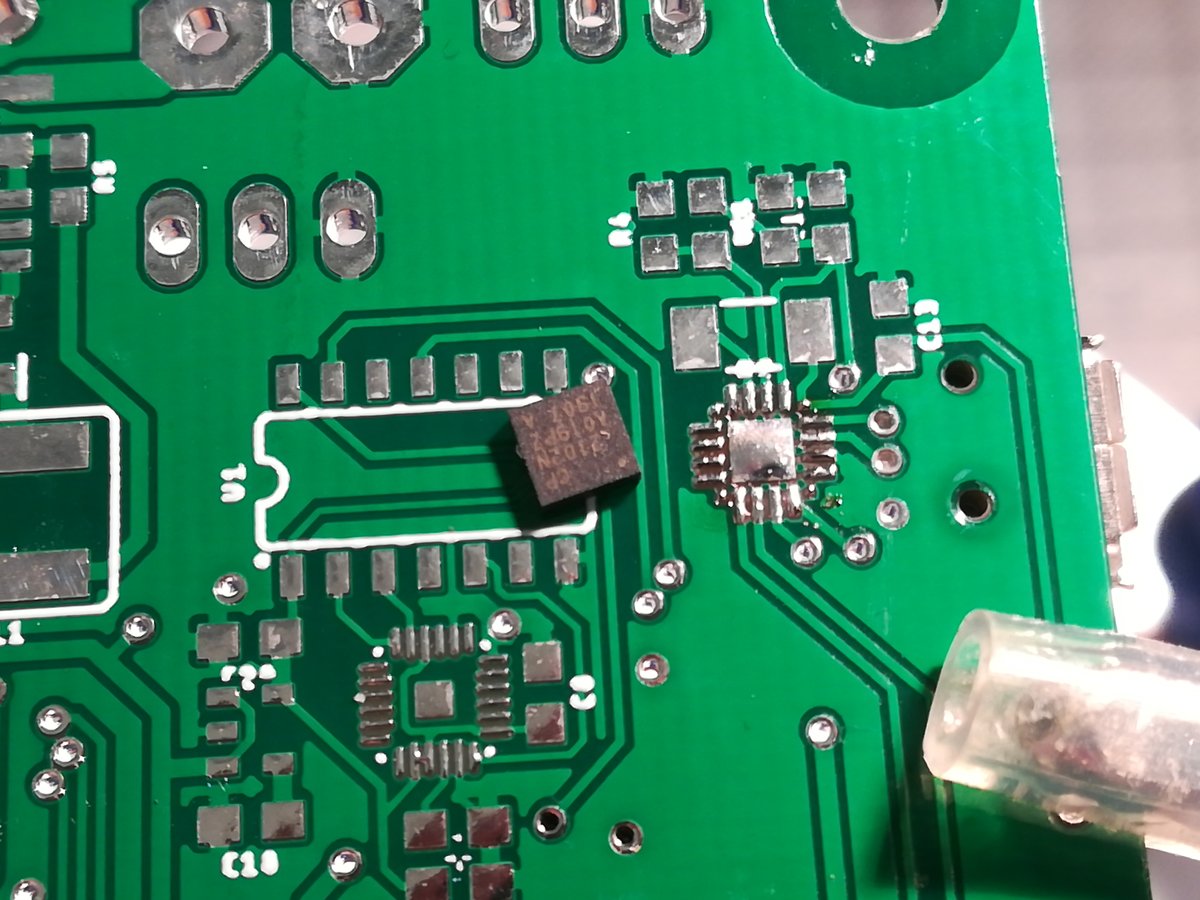
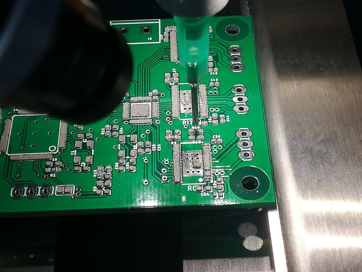
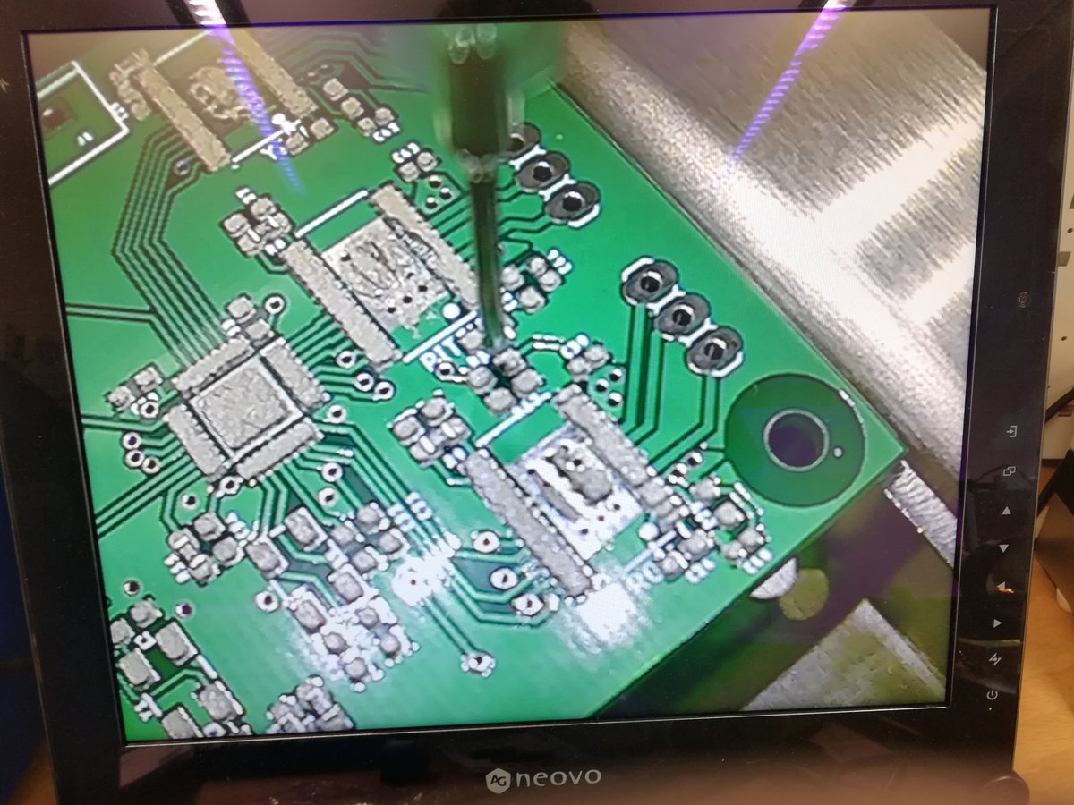
Fortunately, we also had solderpaste with lead, and after the other components arrived, I was able to build a working board.
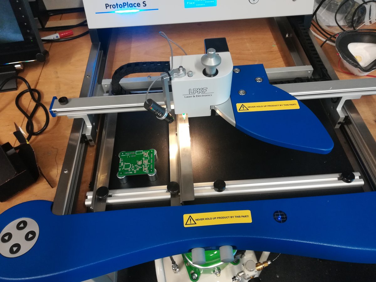
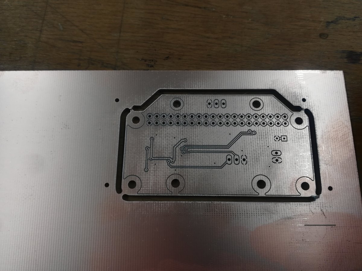
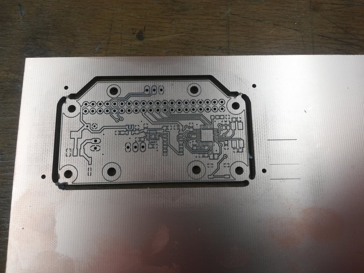
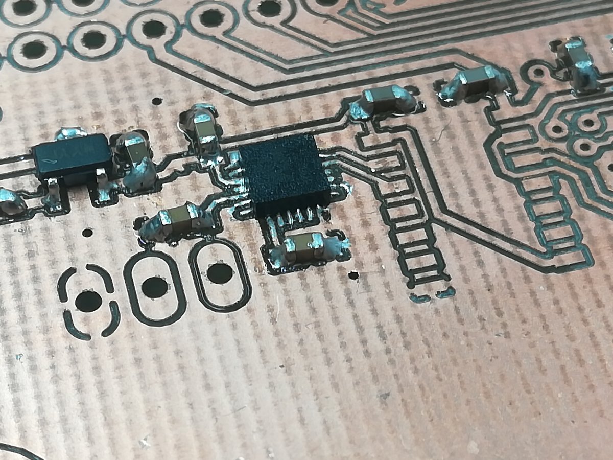
As soon as our PCB mill was working again, I milled the extension board to show that I am able to manufacture my own boards with it. Soldering the extension board was comparably easy, only the orientation sensor was challenging. However, this board worked on the first try.
Setting up the Pi
I downloaded a [raspbian lite] image and prepared the Micro-SD card with the following command:
$ unzip -p raspbian.zip | sudo dd bs=4M status=progress conv=fsync of=/dev/mmcblk0
Make sure to choose the right path to your SD card, or you might mess up your computer.
Under linux, you can find out which device the SD card is by using lsblk.
After the installation process is complete, I configured the pi to automatically connect to my WiFi and start a SSH server, by placing two files in the boot section of the SD card. An empty file named "ssh" will enable the ssh server. A file named "wpa_supplicant.conf" with the following content will setup the WiFi connection (just substitute your country code, SSID, and passphrase):
country=DE
ctrl_interface=DIR=/var/run/wpa_supplicant GROUP=netdev
update_config=1

network={
  ssid="Network name"
  psk="Network password"
}
Now it's possible to log in to the pi via ssh:
$ ssh pi@raspberrypi.local
I installed pip, the python package manager, and a couple of modules needed to capture video streams with the picam and send them over the network:
$ sudo apt-get update
$ sudo apt-get install python3-pip

$ pip3 install picamera[array] opencv-contrib-python zmq imutils
If you do this at home, make yourself a nice cup of tea, because this will take some time.
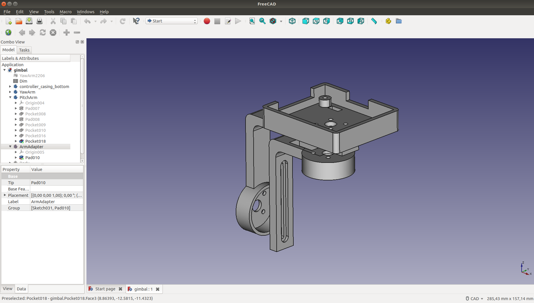
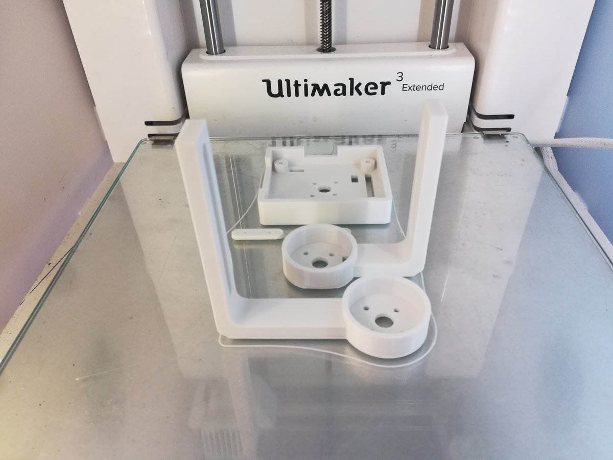
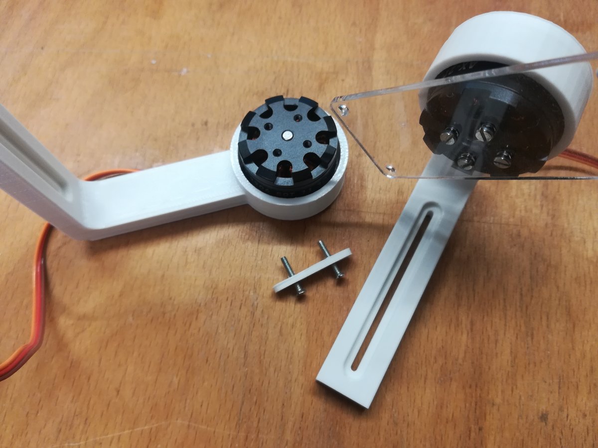
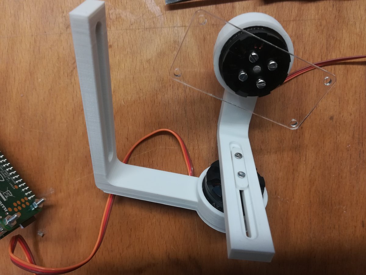
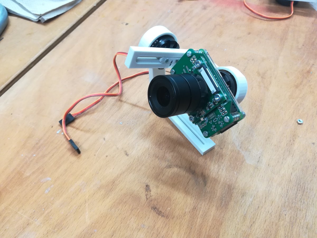
Designing and Printing the Frame
The gimbal frame was designed in FreeCad and consists of a casing for the main controller board, an arm attached to the yaw axis motor, another one attached to the pitch motor, and two adapters that aid in balancing each of the gimbals' axes. I printed the frame on an Ultimaker 3 extended with PLA, using a layer height of 0.15mm with a standard 0.4mm nozzle and 20% infill. The print turned out almost perfectly, with no stringing whatsoever. There were minor deformations on a couple of parts due to insufficient adhesion to the build plate, but all in all the print was fully functional.
Programming the STM32
The STM32F103 series chips are based on the ARM Cortex-M3 microcontroller architecture, which means they are 32-bit processors, unlike the 8-bit AVRs I've used so far. They are vastly more powerful and provide a lot more (and more sophisticated) peripherals and hardware/software features, but they are also considerably harder to program. While most of my programs for AVRs could were structured into one file (or sometimes, a small number of files), this project is too big for such a simple approach.
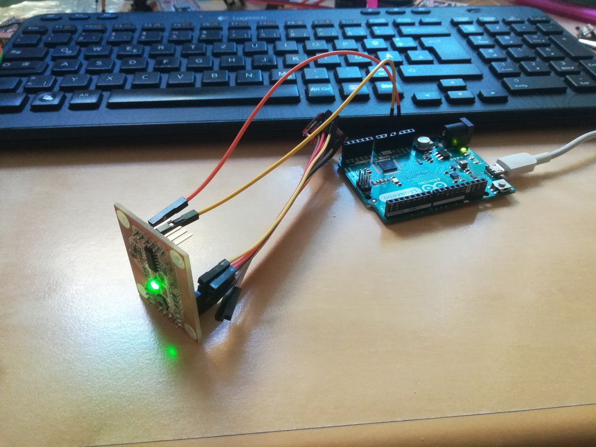
I used the STM32Cube IDE to program the three microcontrollers in C++. In order to upload the compiled binaries onto the chips, I used the ST-Link portion of a Nucleo breakout board. Using only three wires (SWDIO, SWCLK, and ground), the ST-Link provides the ability to program and to debug a target chip, which is helpful to find bugs in complex programs. This functionality is conveniently integrated into the IDE.
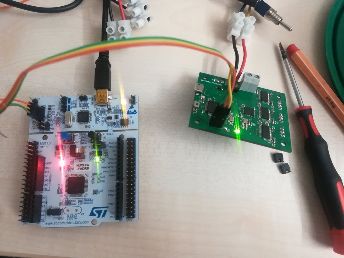
The yellow wire is ground, the other two are serial data and serial clock.
As another integrated tool, STM32CubeMX provides a graphical interface that aids in configuring the peripherals of the target chip and generates boilerplate code. Combined with the hardware abstraction layer (HAL), this makes it vastly easier to program the chip. STM32CubeMX can also be used standalone with your favorite text editor, but I think it's convenient to have it all bundled in one package.
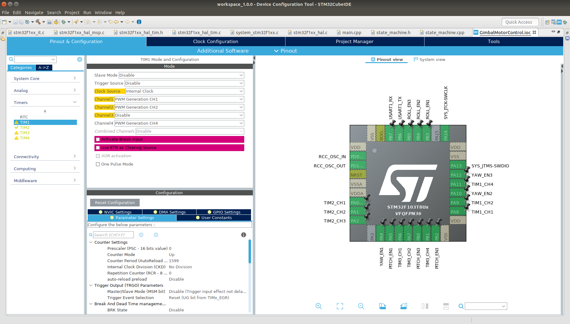
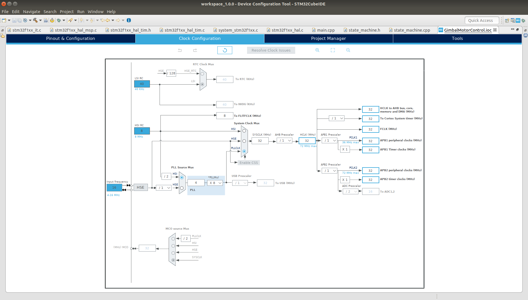
To give you an idea of how the code works, here's a brief explanation of the most critical parts. These are the motor control loop using hardware timers to generate three phase-shifted PWM signals driving the motors, the reading, filtering, and combination of IMU sensor values, and the PID control loop. Then there's also the communication between chips via UART, but most of this is handled by the hardware abstraction layer, so I only needed to implement a simple state machine triggering the correct actions when needed.
First, the motor control. I use sinusoidal control to drive the motors, because it provides smooth movement at low speeds and fine control over positioning. The idea is to generate three PWM signals that induce currents in the motor windings which are 120° phase shifted sine waves. Normally, one needs three half-H bridges (i.e. pairs of transistors) in order to generate these signals; however, on my boards, these are integrated into the BLDC motor drivers. All I have to do is generate three PWM signals with phase-shifted duty cycles on the three input pins of each motor driver. In order to do this, I generate a lookup table for the values of the sine function:
constexpr int table_size = 360;
struct Table {
  int  _values[table_size];

  inline int operator[] (int index) const { return _values[index]; }
};

constexpr Table generate_table() {
  Table tmp{};
  const int mid = 400;
  double a = 0.0;
  for(int i = 0; i < table_size; i++) {
    a = i * 3.141592 / (table_size / 2);
    tmp._values[i] = mid + (mid - 1) * sin(a);
  }
  return tmp;
}

const Table sin_table = generate_table();
The number of entries is rather arbitrary; a higher number corresponds to slower, but more precise movement. The entries in the table define the duty cycle of the PWM signal. I configured the timer so that it oscillates between 0% and 50% duty cycle. A higher duty cycle provides more torque, but generates more heat in the motor windings (and they can get quite hot even at 50% duty cycle). Now, to advance the motors, I update the compare register of the corresponding timer peripheral:
__HAL_TIM_SET_COMPARE(&htim1, TIM_CHANNEL_1, sin_table[motor_position[0]]);
__HAL_TIM_SET_COMPARE(&htim1, TIM_CHANNEL_2, sin_table[motor_position[1]]);
__HAL_TIM_SET_COMPARE(&htim1, TIM_CHANNEL_4, sin_table[motor_position[2]]);

__HAL_TIM_SET_COMPARE(&htim2, TIM_CHANNEL_1, sin_table[motor_position[3]]);
__HAL_TIM_SET_COMPARE(&htim2, TIM_CHANNEL_2, sin_table[motor_position[4]]);
__HAL_TIM_SET_COMPARE(&htim2, TIM_CHANNEL_3, sin_table[motor_position[5]]);

__HAL_TIM_SET_COMPARE(&htim3, TIM_CHANNEL_1, sin_table[motor_position[6]]);
__HAL_TIM_SET_COMPARE(&htim3, TIM_CHANNEL_2, sin_table[motor_position[7]]);
__HAL_TIM_SET_COMPARE(&htim3, TIM_CHANNEL_4, sin_table[motor_position[8]]);
The target motor position is provided regularly by the main controller. Whenever a byte arrives on the UART line, an interrupt gets triggered, and the arriving data is processed to update the state of the motor controller:
uint8_t id = (rxbuf[0] | ID_MASK) >> 5;
uint8_t cmd  = rxbuf[0] & CMD_MASK;

if(id != MY_ID) return;

if(state == FAULT) {
  send_byte(NOT_OK);
}

switch(cmd) {
case HELLO:
  txbuf[0] = MY_ID << 4 | state;
  HAL_UART_Transmit_IT(&huart1, txbuf, 1);
  break;
case CALIBRATE:
  if(state == READY) {
    state = CALIBRATING;
    send_byte(OK);
  } else {
    send_byte(BUSY);
  }
  break;
case START:
  if(state == INIT || state == CALIBRATING) {
    send_byte(BUSY);
  } else {
    send_byte(OK);
    enable_motors();
    start_pwm();
  }
  break;
case STOP:
  if(state == INIT || state == CALIBRATING) {
    send_byte(BUSY);
  } else {
    disable_motors();
    stop_pwm();
    send_byte(OK);
  }
  break;
case UPDATE:
  for(int i = 0; i < 3; i++)
    error_signal[i] = rxbuf[2+i];
  break;
default:
  send_byte(NOT_OK);
  break;
}
The state machine of the IMU unit looks very similar; when asked for updates, it provides the main chip with the latest orientation data. To calculate orientation reliably and consistently, I use a filter developed by Sebastian Madgwick, which combines the orientation sensors' gyroscope, accelerometer, and magnetometer readings to calculate the orientation of the sensor relative to its initial orientation. The algorithm returns a quaternion, which is transformed into euler angles, whose integer representation is sent via UART to the main controller. While updating the euler angles, interrupts need to be disabled to avoid sending inconsistent data.
MadgwickAHRSupdate(
  imu.gx, imu.gy, imu.gz,
  imu.ax, imu.ay, imu.az,
  imu.mx, imu.my, imu.mz
);

float tmp[3];
tmp[0] = atan2(2 * (q0 * q1 + q2 * q3), 1 - 2 * (q1*q1 + q2*q2));
tmp[1] = asin(2 * (q0 * q2 - q3 * q1));
tmp[2] = atan2(2 * (q0 * q3 + q1 * q2), 1 - 2 * (q2*q2 + q3*q3));

while(sending);
__disable_irq();
euler[0] = tmp[0] * 65535 / 3.141592f;
euler[1] = tmp[1] * 65535 / 3.141592f;
euler[2] = tmp[2] * 65535 / 3.141592f;
__enable_irq();
The main controller is constantly fetching updates from the IMU controller, recalculating the difference from actual orientation to desired orientation, and updating the motor controller's error signal. In the heart of these operations is the PID control: based on the errors up to the current time, it calculates three values that are summed up to decide how the motors should be actuated to compensate for the error. The proportional part is dependent on the current error rating only; the larger the error, the larger the corrective action. The integral part gets larger the longer the error persists, and the derivative part reduces overshoot by incorporating the rate of change in the error.
for(int i = 0; i < 3; i++) {
  cur_error[i] = -orientation[i];
  float P = KP * cur_error[i];
  integral[i] += cur_error[i];
  float I = KI * integral[i];
  float D = KD * (cur_error[i] - last_error[i]);

  last_error[i] = cur_error[i];

  error_signal[i] = P + I + D;

  if(error_signal[i] > max_signal) error_signal[i] = max_signal;
  else if(error_signal[i] < min_signal) error_signal[i] = min_signal;
}
The system is kind of working, but there is lots of room for improvement. But at least it's moving.