
Output devices in general
Anything that is powered by some electronic signal can be used as an output device. From simple LED's and LED strips/arrays over video output, displays (LCDs), speakers, servo/stepper/brushless motors or other stuff. All those devices need to get the information what to do and that can be done by some protocol specific for this device, standard communication (I2C, SPI, UART), or just pulse width manipulation. For more sophisticated devices like displays, you can use a controller board which takes away a lot of the low-level details, which might be too much work if you just want to display some information.
E-Ink display
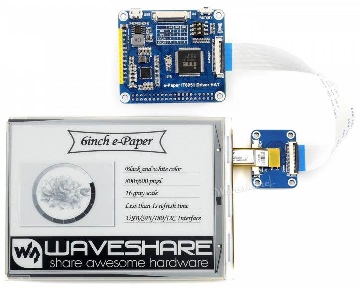
I wanted to work with an e-ink display because I like this technology. A display that is static, easily read under sunlight, needs nearly no power to work is just amazing. As the refresh rates are slow compared to traditional displays, it's more useful for displaying static information than videos. Today they are also mostly black and white displays. There are some that also have three colors, but they are definitely not full-color displays. I wanted to work with the waveshare 6-inch e-paper display, but it is not sold at the moment. This specific display has the advantage of being able to do a full refresh in under a second compared to the most other waveshare displays. Also it has the capability to update the image only partially, which is really nice. Displays with 4s refresh time and no partial update are not interactive enough for a lot of applications. It might be available in one week, so I hope I can update this in then next time!
LED strip
So I decided to play around with an LED Strip with individually addressable LEDs (W2812B). LED Strips are easily available and quite cheap, they are a great way to light up something. This way I would understand the strip in more detail than just using some library.
The board
I decided I want to use the ATTiny44, so I just used the same board from last week. If you want to learn more about this, have a look at the input device week.
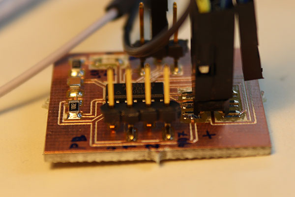
The attiny44 board
Fixing timing problem on the attiny44
Before I come to the LEDs at all I first need to fix some timing issues I realized during the last assignment. Because to address the LED strip you need to be able to exactly time when you send data. So I needed to set the clock divide fuse to the right value because with the standard value the fuse is set to divide the clock by 8, which means that the attiny is just running at 1 Mhz. You can set the clock fuse to a divider of 1 by the command avrdude -p t44 -P usb -c usbtiny -U lfuse:w:0xE2:m using the USBtinyISP and avrdude. Otherwise you could also set this in the software, but I prefer it this way. So now the clock is faster for all programs on the attiny.
The W2812B LEDs
Before programming I want to explain how the LED strip is addressed.
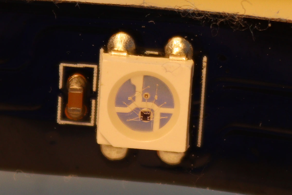
The LED in close up
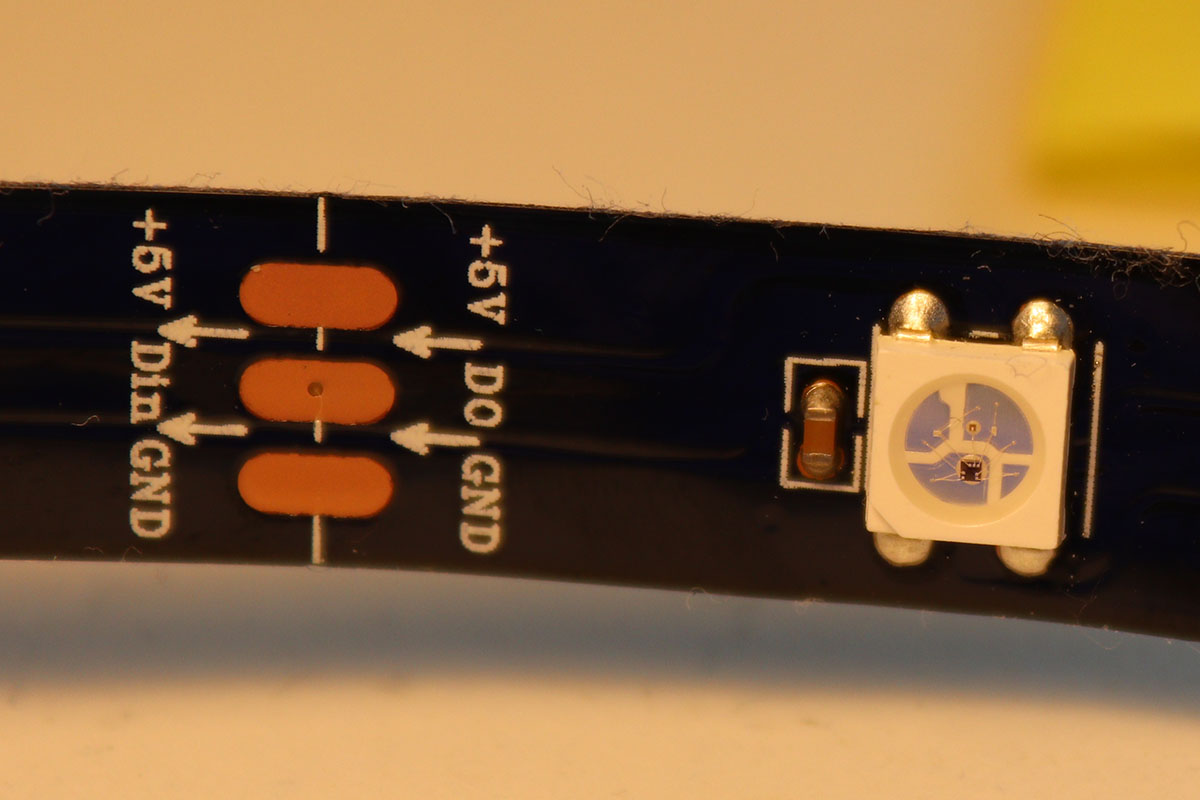
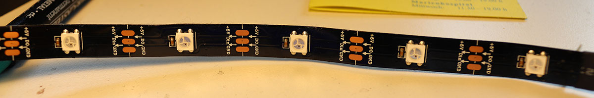
The connections on the strip
You can find the datasheet for the WS2812B LEDs here. With this datasheet I figured out how to work with the LEDs. The strip needs to be powered by 5V, a GND pin and a data pin. According to the datasheet the voltage levels for the data are 5V ones, but it also works with 3.3V logic levels. All the LEDs on the strip are connected together. So you send the color values for all the LEDs after each other and then a reset signal. Each LED removes it's own values from the sent values, stores the value and sents the rest of the data to the next LED. When the reset signal is read the LED updates it's color to the saved value. For each LED you send 24bit data, which is in the format GRB. So the first 8 bit are the green value, then red and then blue.
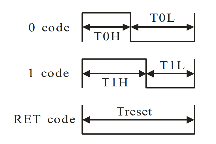
The logic of the WS 2812 LED
Above the signals for 0, 1 and reset are shown. The timing values are TOH: 0.4us, TOL: 0.85us, T1H: 0.8us, T1L: 0.45us and reset time is bigger than 50us. This is a really really small amount of time and one cycle on 8Mhz is already 0.125us long.
Programming
Last week I found that the attiny can give a current of 40mA per pin, to a max of 200mA. But each of the LEDs can draw over 50mA on full brightness, so I used an external power source to power the LED strip. In the group we also tested my LED strip for how much power the LEDs actually draw. We measured the current over 10 LEDs on full brightness white and full brightness each color individually. On white each LED draws 33mA, each single color 11mA. This is less then mentioned in the datasheet! This is also what is mentioned in the link above: It looks like there are two types of the same chip with different current consumptions. But nevertheless it is a lot of current when you want to light up a few meters of LED strip.
To address the LEDs you just send the data for the LEDs one after another. To get the timing right I wrote the function to send a 0 and a 1 as a define "function". So every send0() will be replaced in the rest of the code. This is necessary because function calls are an overhead that is too big and takes too long, remember that we can only have 3 cpu cycles for one signal. Then I apply a voltage to the pin, wait for as long as I need and put the voltage to 0. I wait using assembly inline code, which is written using the asm volatile keyword. Waiting in assembly can be done using the nop keyword, which just stands for "no operation". That means just doing one cycle nothing.
//Send 0
#define send0() PORTA |= (1 << LED_DATA_PORT); asm volatile("nop \n nop \n nop"); PORTA &= ~(1 << LED_DATA_PORT); asm volatile("nop \n nop \n nop \n nop \n nop \n nop \n nop");
//Send 1
#define send1() PORTA |= (1 << LED_DATA_PORT); asm volatile("nop \n nop \n nop \n nop \n nop \n nop"); PORTA &= ~(1 << LED_DATA_PORT); asm volatile("nop \n nop \n nop \n nop");
Above is the first implementation I did, which was straight from the datasheet. But it didn't work, because applying a voltage to a pin also needs time. So I wrote different versions, where I assumed the I/O operation would take 1,2,3 cycles and so on. Then I tested which worked and the ones with 2,3,4 cycles for the I/O operation worked, the rest didn't. So below is the real function to send 0 and 1 to the LED strip.
// I/O 3 cycles
//Send 0
#define send0() PORTA |= (1 << LED_DATA_PORT); PORTA &= ~(1 << LED_DATA_PORT); asm volatile("nop \n nop \n nop \n nop");
//Send 1
#define send1() PORTA |= (1 << LED_DATA_PORT); asm volatile("nop \n nop \n nop"); PORTA &= ~(1 << LED_DATA_PORT); asm volatile("nop");
In my code the setup of the pins is done in the following way:
#define LED_DATA_PORT PA3
// Set the LED port number as output.
DDRA |= (1 << LED_DATA_PORT);
// Init LED data pin with 0
PORTA &= ~(1 << LED_DATA_PORT);
Lighting up a LED in the main code works as following. This will ight up the LED green.
send1(); send1(); send1(); send1(); send1(); send1(); send1(); send1(); // GREEN
send0(); send0(); send0(); send0(); send0(); send0(); send0(); send0(); // RED
send0(); send0(); send0(); send0(); send0(); send0(); send0(); send0(); // BLUE
// RESET to light up the LED
PORTA &= ~(1 << LED_DATA_PORT); _delay_us(50);
You can put as many LEDs before the reset as your program memory allows. I tried to refactor the code and make a real function from it, so every LED would take considerably less program memory. Now it is kind of hard-coded, which is really bad. But somehow function calls and if statements take too many cycles and also not the same amount every time, so I wasn't able to change the code to something better. I think one time it would have worked, but then I could only light up the LED one time and not change the value anymore. I have no idea what the problem there was, but I guess the attiny just has too less memory to work with these LED strips with this high data frequency dynamically.
My code which is at the bottom of the page lights up the first 10 LEDs in different colors and the first one is blinking from red to green.
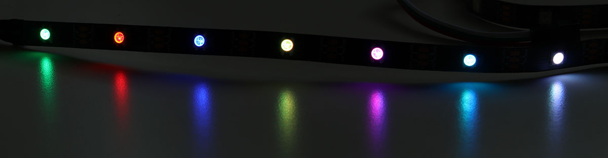
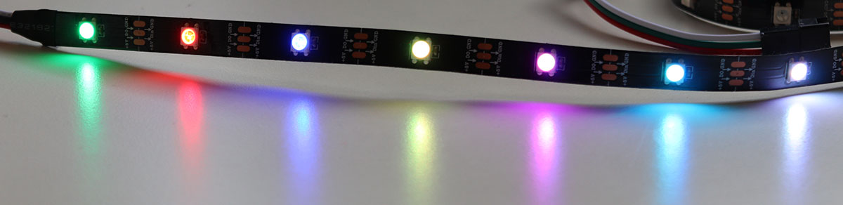
Demonstration
Here you can see the LED strip light up. When taking the picture with my DSLR and using a very fast shutter speed, you can really see the colors, and where exactly on the W2812B LED chip which color LED is placed.

The LED strip lit up
The LED strip lit up
The LED strip lit up
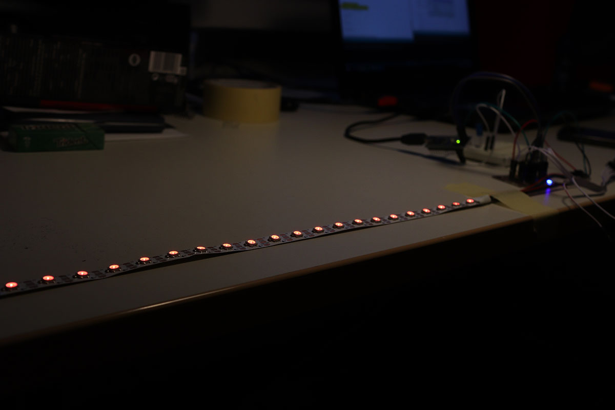
The LED strip lit up all in red, 60 LEDs/m
Files
Here you can download the files created during this week:
The code to control the LED strip