Board
First of all I created a new board for this week, because the Bluetooth module has 3.3V logic levels. So I designed a new board around the ATtiny44 with a 3.3V voltage regulator on it. With a jumper you can choose if the attiny should be powered with 5V or 3.3V, depending on your use case. Also I added a few pins on the board for the power supply of devices used with the board. There are ground, 5V and 3.3V pins which each can supply more current than can be drawn from the attiny itself. 5V is only limited by the power supply which powers the board and the voltage regulator gives 1A at 3.3V. As I have already shown the process of creating a board extensively in the last weeks today I will only show the board design. The schematic is also not very interesting. I also had a Micro USB connector on the board to power it from a standard USB cable, but unfortunately the ordered ones were upright and broke off after the first connection.

The board design
Bluetooth Networking
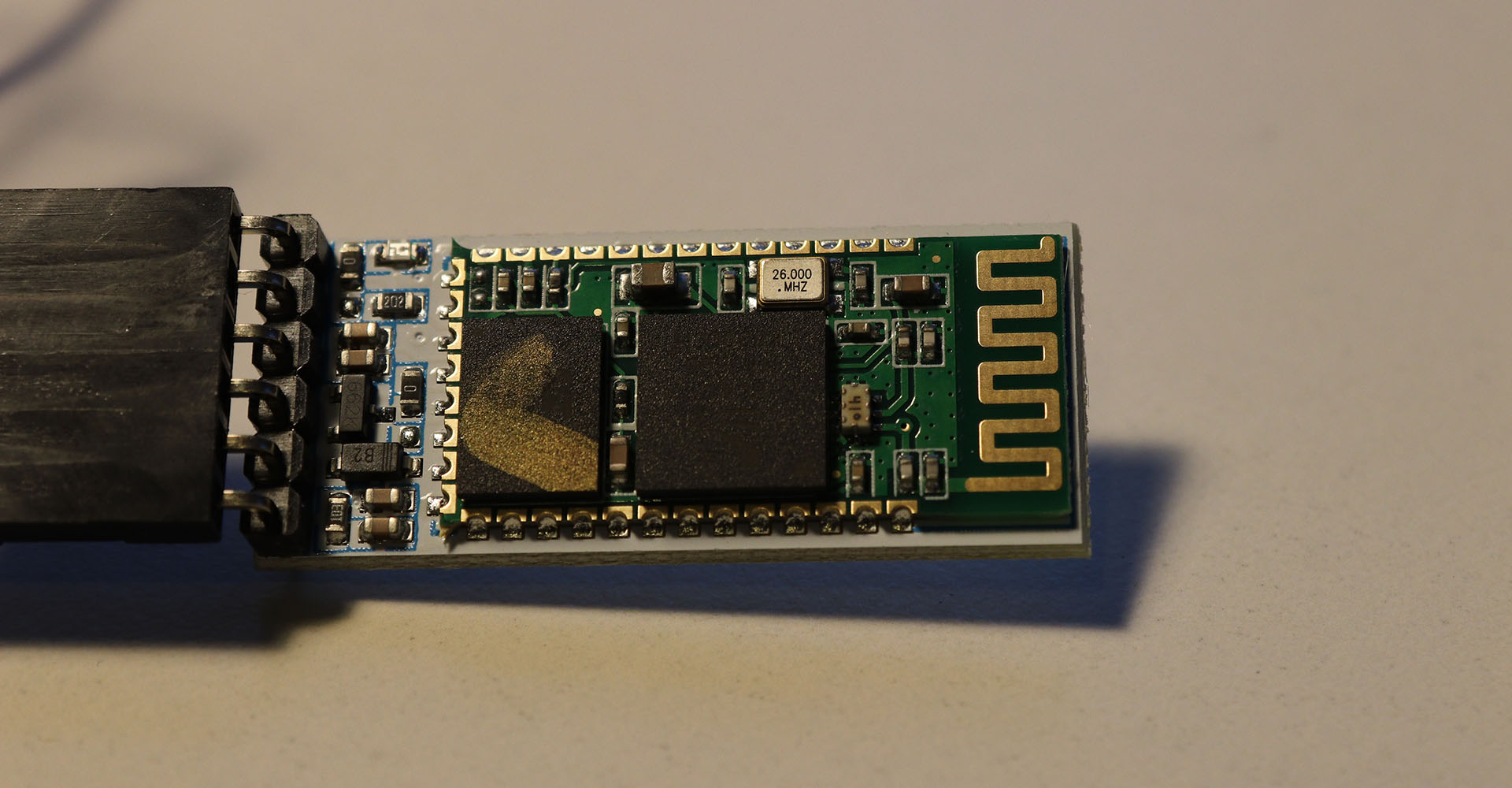
To get a start with the world of bluetooth I decided to use the HC-05 module, which is a very easy hobbyist module. Below is the setup I used: I used the arduino nano again as programmer, the board was directly connected with the bluetooth module and the LED strip on the left. Every time I wire up the module I get RX and TX switched around, but that is something that is easily found.
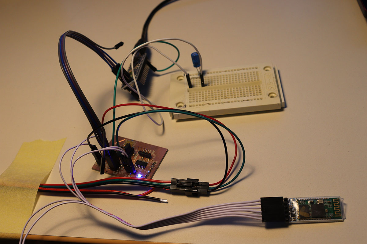
The HC 05 module wired up
I found a nice german webpage which explained the module and the basic commands as well as the connection to it from various devices. You can just connect to the HC-05 Module from any of your devices with a serial terminal and the bluetooth module will open a serial connection over bluetooth. So you can communicate with your board via easy text commands. On my Laptop I used this program, under Android I used this app.
Programming
For the programming I used the Arduino IDE again and there I used the SoftwareSerial library, which did all the low-level UART stuff for me. To open the connection you just need to tell the SoftwareSerial library which pins and baud rate to use. The library is quite big, but for this program it was still okay. If it is too big for you, you can also make the software serial incoming buffer smaller.
#include "SoftwareSerial.h"
#define RxD 2
#define TxD 1
SoftwareSerial blueToothSerial(RxD,TxD);
pinMode(RxD, INPUT);
pinMode(TxD, OUTPUT);
setupBlueToothConnection();
The setupBlueToothConnection function sets the HC-05 Module into the correct mode to connect to it and sets a name for the module:
void setupBlueToothConnection()
{
  blueToothSerial.begin(9600); //Set Bluetooth Baud Rate to default
  blueToothSerial.print("\r\n+STWMOD=0\r\n"); //set the bluetooth work in slave mode
  blueToothSerial.print("\r\n+STNA=HC-05\r\n"); //set the bluetooth name as "HC-05"
  blueToothSerial.print("\r\n+STOAUT=1\r\n"); // Permit Paired device to connect me
  blueToothSerial.print("\r\n+STAUTO=0\r\n"); // Auto-connection should be forbidden here

  delay(2000); // This delay is required.
  blueToothSerial.print("bluetooth connected!\n");

  delay(2000); // This delay is required.
  blueToothSerial.flush();
}
In the main program I then wait until data is sent over the bluetooth connection and if so I read it and turn the LEDs on according to what was sent. So '1' means white, '0' means turn off, 'r' means red, 'g' green and 'b' blue. Here is the code for the command '1':
while(blueToothSerial.available()){
recvChar = blueToothSerial.read();

if ( recvChar == '1' ) {
    for (char i = 0; i<25; i++) {
      //LED1
      // GREEN
      send0(); send0(); send0(); send1(); send0(); send0(); send0(); send0();
      // RED
      send0(); send0(); send0(); send1(); send0(); send0(); send0(); send0();
      // BLUE
      send0(); send0(); send0(); send1(); send0(); send0(); send0(); send0();
    }
}
If the connection doesn't work it is a good idea to use the following main loop in the program, this will send the message Bluetooth Test to the connected device. So if you think you are connected but you can't receive this message, you should check the connections from the bluetooth module to your chip. If you are connected to the module is indicating by the blinking frequency of the module, slow frequency means somebody is connected.
void loop()
{
  while(1){
    blueToothSerial.println("Bluetooth Test");
    delay(1000);
  }
}
Demo
In the video I show the working connection.
Files
Here you can download the files created during this week:
The eagle files for the new board
The program file