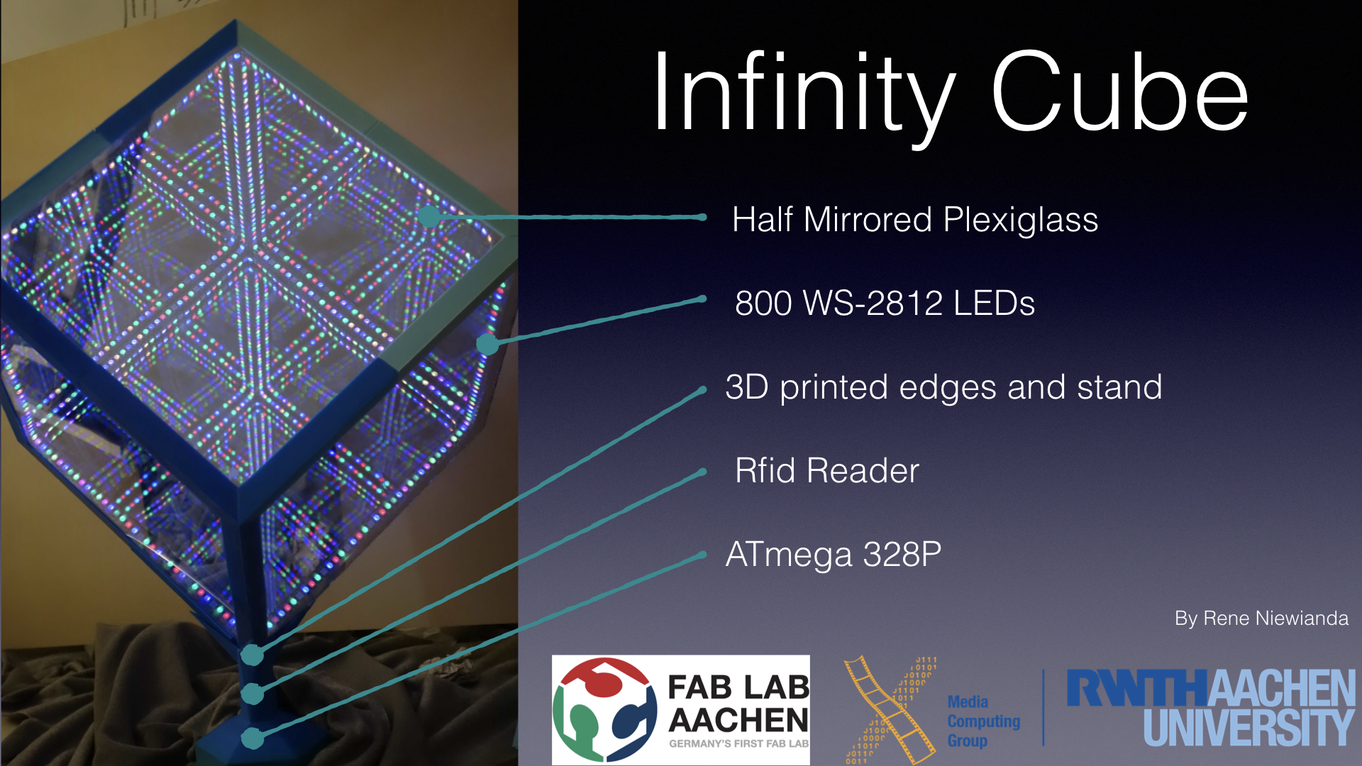
RFID Controlled Infinity Cube
Project Details
- 3d printed Base
- Laser cut sides
- Different light and (sound) settings based on sensor input
- Settings changeable via nfc tagged parts/app
- The instructable that inspired me
- Initial proposal
Planned Materials
- 1x Spy Mirror acrylic glass
- 1x RFid Card reader
- 1x Ws28/12 Stripes (144 Leds per Meter)
- 1x Acrylic Glass
- 1x (Fancy PLA for the Base)
- 1x Microcontroller ATMega 328P
Plan
- Calculate things for the cube
- Cut corpus
- Glue Leds
- Cut Mirrors
- Glue cube
- Design and Print Cube Base
- Design and solder electronics
- Maybe mill base for sensor casing etc.
How To build the Cube
I started by Laser cutting the cube itself. I made the svg with a tool called
Box Designer where you simply enter the measurements of
the desired box and it generates an svg that you can cut. I provided 2 ready to cut files (ist a simpler version)
you need to cut on 4 times and one 2 times they are labeled, so you know which is which.
I had a few problems with or Lasercutter because the
parts are about 28x28 cm long and the maximum cutting size of you cutter is 30x60cm. The software tends to resize
svg when the size is near the maximum cutting size, so i had to resize them again by hand (after looking up the exact measurements via inkscape).
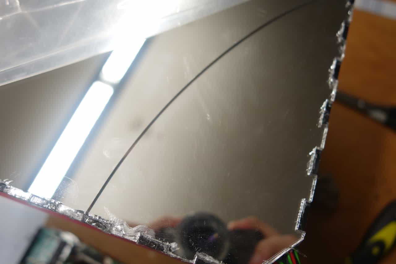
Another thing worth mentioning is that you should leave the protection foil on the glass because the mirror surface is scratched very easily.
Next thing I designed was the inner corpus this is used to hold the Leds in place. This is necessary because if
you glue the Leds directly onto the mirrors the mirror surface might be damaged. Here I used inkscape to
make the svg. The individual parts are basically rectangles with cutouts. I used 5mm acrylic glass for the corpus.
Assemble the corpus like this and glue is together. I recommend that you use special glue for acrylic glass.
Do not forget that you need to remove the protection foil before assembling it.
Do not forget that you need to remove the protection foil before assembling it.

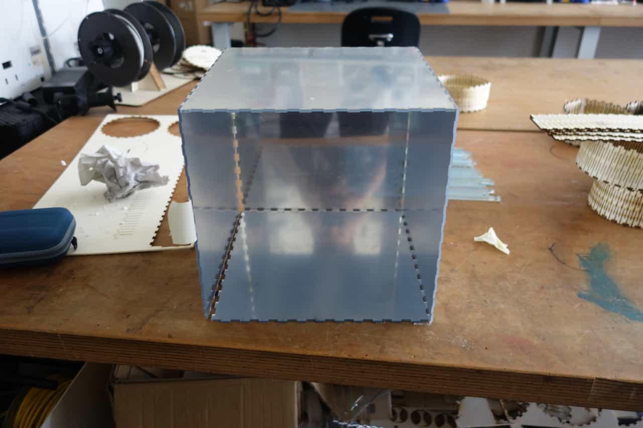
The assembled corpus should look like this.
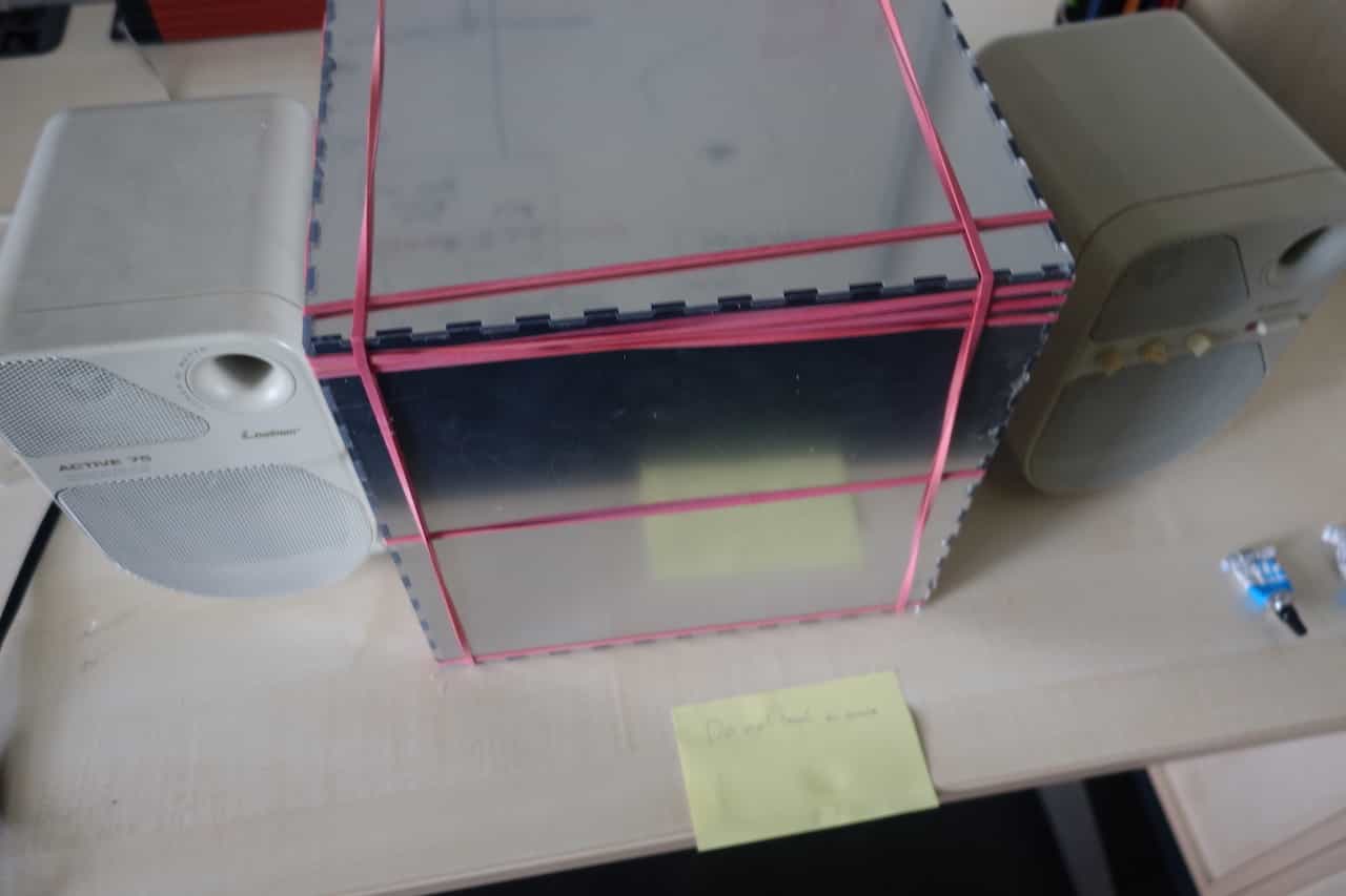
Next assemble the mirrors. Pre assemble it (without glue) and use tape to keep it together. This is to make sure
that you know where every part has to be placed. Then disassemble it again, lay it out in a way that you remember
were you have to put every part and start gluing. Remove the inner foil
and use the corpus as support and orientation. Leave one tile "unglued" so you still have access to the inner
parts of the cube. To hold everything in place while drying you can use clamps or rubber band.
(Warning: If you use rubber bands and they come in contact with the glue the solvent of the glue makes them rigid so they might snap and fly across the room).
When the glue has dried remove the corpus.
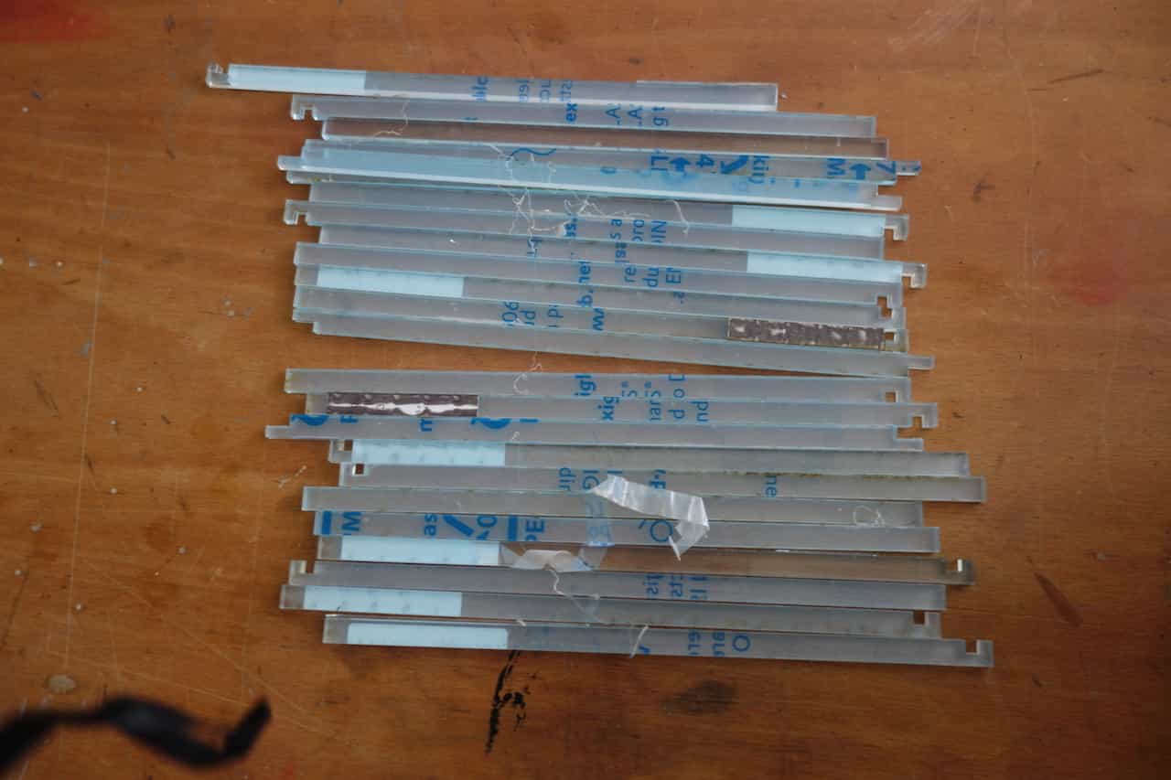
Now you have to cut the Led-stripes to the correct length when using my files you need around 99cm per side.
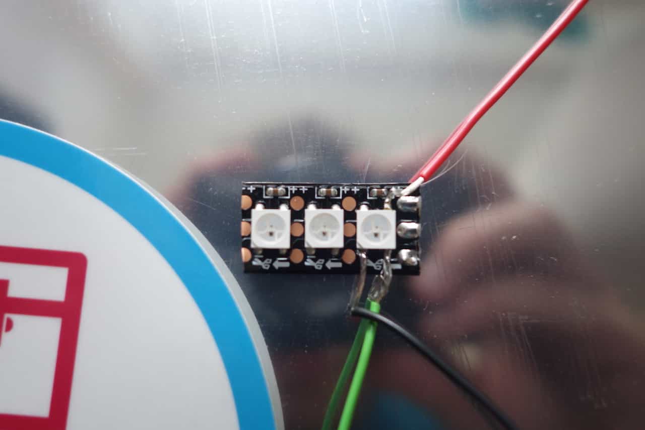
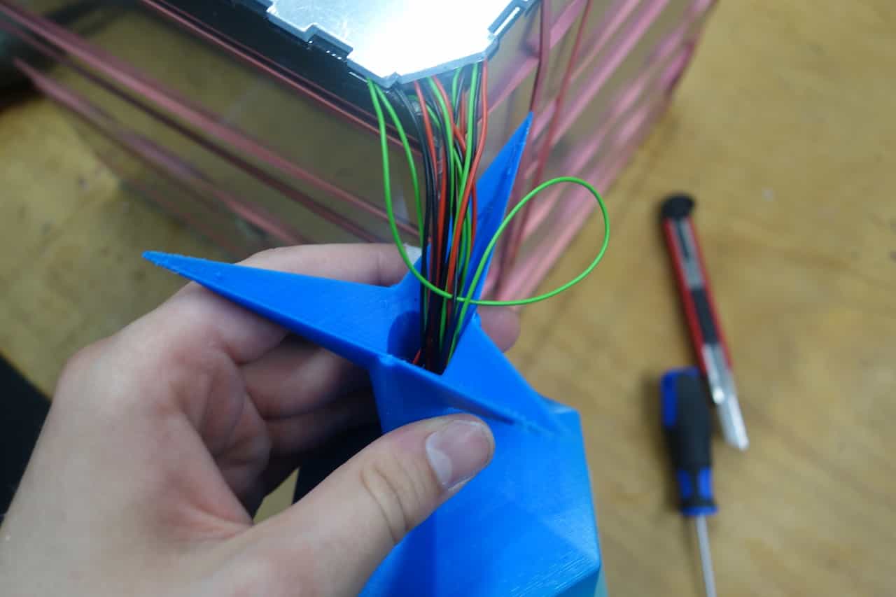
Keep in mind that the stripes only work in one direction. So sometimes you have to solder new wires to the stripes. Normally the are pad to do this bun in my case the pads where to small after cutting. As a workaround you can solder the wires directly to the Led like this: green = Data In , Black = GND , red = VCC. If you using other stripes you can look up the pin layout in the datasheet of Leds. My stripes had tape on the back so I did not need additional glue to attach them to the corpus.
Keep in mind that the stripes only work in one direction. So sometimes you have to solder new wires to the stripes. Normally the are pad to do this bun in my case the pads where to small after cutting. As a workaround you can solder the wires directly to the Led like this: green = Data In , Black = GND , red = VCC. If you using other stripes you can look up the pin layout in the datasheet of Leds. My stripes had tape on the back so I did not need additional glue to attach them to the corpus.
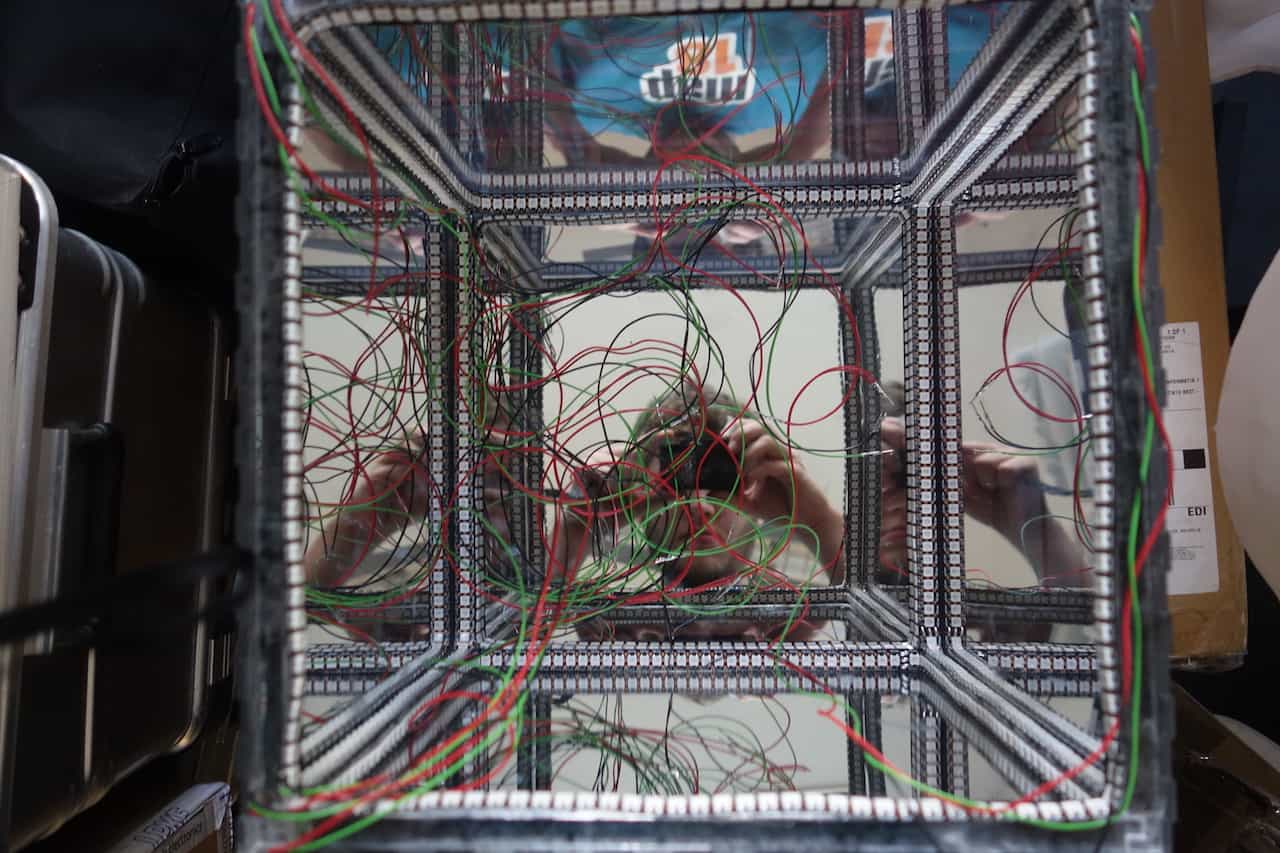
The corpus should now look like this when placed into the cube.
While attaching the Leds put the corpus into the cube one in a while to make sure that it still fits. If it doesnt fit you have to push the Leds a little more to the inside of the cube (In my case the stripe was slightly wider than the corpus). You should layout the wire in such a way that the all end up in a single corner. use tape to hold the in place and make sure that they cannot be seen from the outside i.e. that the are always between the corpus and the mirror hull because there they will be hidden by the 3D printed edges later on.
While attaching the Leds put the corpus into the cube one in a while to make sure that it still fits. If it doesnt fit you have to push the Leds a little more to the inside of the cube (In my case the stripe was slightly wider than the corpus). You should layout the wire in such a way that the all end up in a single corner. use tape to hold the in place and make sure that they cannot be seen from the outside i.e. that the are always between the corpus and the mirror hull because there they will be hidden by the 3D printed edges later on.
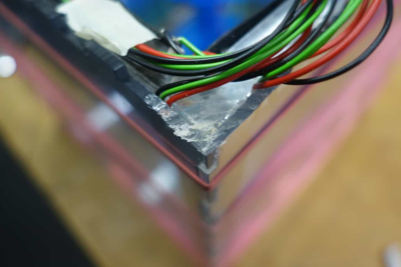
Make a little cutout in the edge were the wires to "leave" the cube. I used a Dremel for this.
Warning: Do not cut the wires. Sometimes the acrylic glass will melt while cutting so to not touch the cutting area or you will burn your fingers like me.
Warning: Do not cut the wires. Sometimes the acrylic glass will melt while cutting so to not touch the cutting area or you will burn your fingers like me.
Before you attach the last plate check if every stripe works correctly. simply wire it to an Arduino or my
Fakeduino and use some code from from the Output Assignment.
Now can can glue the top part onto the cube. While I was doing that some Leds in the inside
got loose, so I tried to reopen the cube again. At this point the glue had dried a little bit and I used to
much force and broke the glass plate. When you try opening the cube a gain be very careful while opening it an you
might as well apply some solvent to the edges so the glue will dissolve.
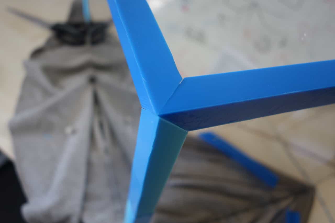
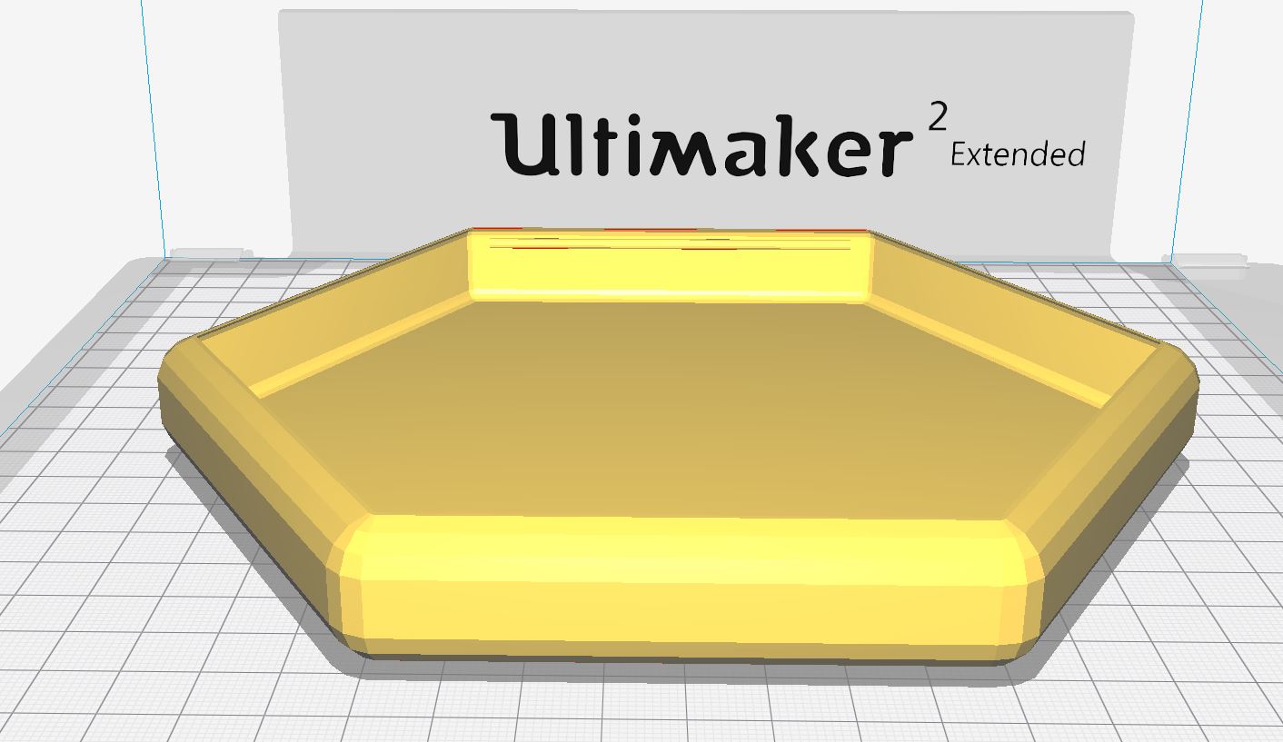
To attach the stand simply guide the wires to the hole in the center the stand is not glued to the cube. The stand was 3D-printed on a Prusa Mk2 (PLA) without support. For the part where
the cube connects to the stand (topmost part) I got help from Jan Thar because the calculations where quite complicated.
I made the stand using Open-Scad and then Cura to 3D print it.
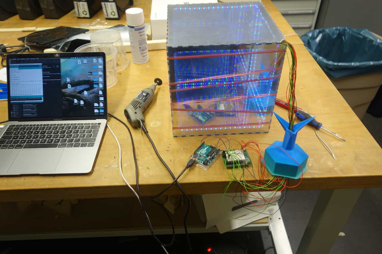
Now I tested everything again. Usually i use an Arduino Uno to test my systems because it has an USB-Serial
connection other then the board I will use in the final product. The LEDs brightness should be turned down
to 5 so a 5v/1A power source can power all Leds at once if you use a bigger power source you need to use separate
sources for the Leds and the board otherwise the chip might get fried.
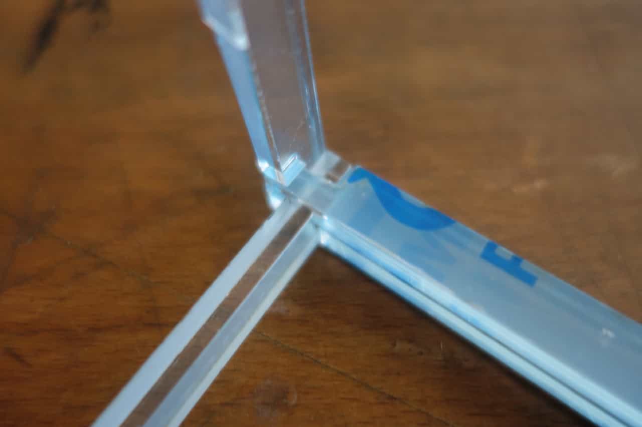
The last thing thats left to glue are the edge-tiles of the cube. Here you must be careful not to spill glue
on the center of the surfaces. These parts are 3D printed on the Prusa again without support. For the complete
cube you need 24 parts, two for each edges. You may need to cut the tiles where the cables leave the cube for
this I used a pair of scissors.
Programming the RFID chips
RFID (radio-frequency identification) is a technique for sender-receiver-systems and works without contact.In this project I use a simple RFID transmitter and rewritable Tags. The advantage of the tags is that they do not need any power source they are powered inductively from the antenna of the transmitter. I will only write use three bits of the tag so its capacity is irrelevant.
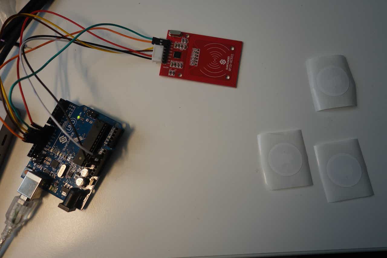
To write on the tags use the write code And connect the pins like this:
SDA -> 10
SCK -> 13
MOSI-> 11
MISO -> 12
IRQ -> Not needed
RST -> 9
VCC -> 3,3V
GND -> GND
You can configure the pins individually in the code via the defines. I used the MFRC522-RFID Module with this Library.
SDA -> 10
SCK -> 13
MOSI-> 11
MISO -> 12
IRQ -> Not needed
RST -> 9
VCC -> 3,3V
GND -> GND
You can configure the pins individually in the code via the defines. I used the MFRC522-RFID Module with this Library.

The programm waits for input when a string is provided via the Serial the programm waits for a chip top be
placed on the transmitter then it writes the input in blocks of 4 byte onto the chip. If you use ASCII symbols
every symbol has the size of 1 byte. When everything is written the first 3 bytes saved on the chip are read
to see if everything has worked correctly. The number of bytes read can be changes if you like but I only need
3 byte here.
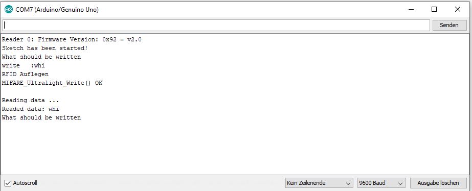
The serial in and output looks like this.
Write 3 chips: one with "red", one with "blu" and one with "whi".
In the picture you can see the process for "whi"
Wiring up
Connect all data cables from the Leds to pin 6 of the fakeduino and the RFID-reader like this:
SDA -> 10
SCK -> 13
MOSI-> 11
MISO -> 12
IRQ -> Not needed
RST -> 9
VCC -> 3,3V
GND -> GND
Connect everything to your power source (Leds,rfid, and Fakeduino). Since the RFID-reader needs 3.3V instead of 5V like the rest I reused the voltage divider I used for the Bluetooth-Assignment.
SDA -> 10
SCK -> 13
MOSI-> 11
MISO -> 12
IRQ -> Not needed
RST -> 9
VCC -> 3,3V
GND -> GND
Connect everything to your power source (Leds,rfid, and Fakeduino). Since the RFID-reader needs 3.3V instead of 5V like the rest I reused the voltage divider I used for the Bluetooth-Assignment.
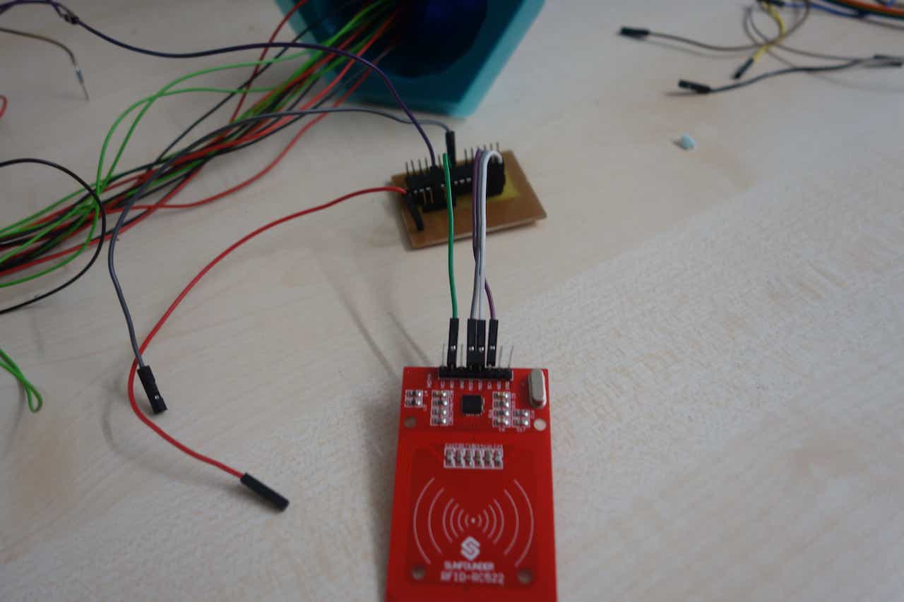
Place the RFID-reader like this it works better with a one where pins are straight when the bis are straight like
here it is a tight fit.
The RFID-Reader should detect the chip when is placed like in the picture.
The RFID-Reader should detect the chip when is placed like in the picture.
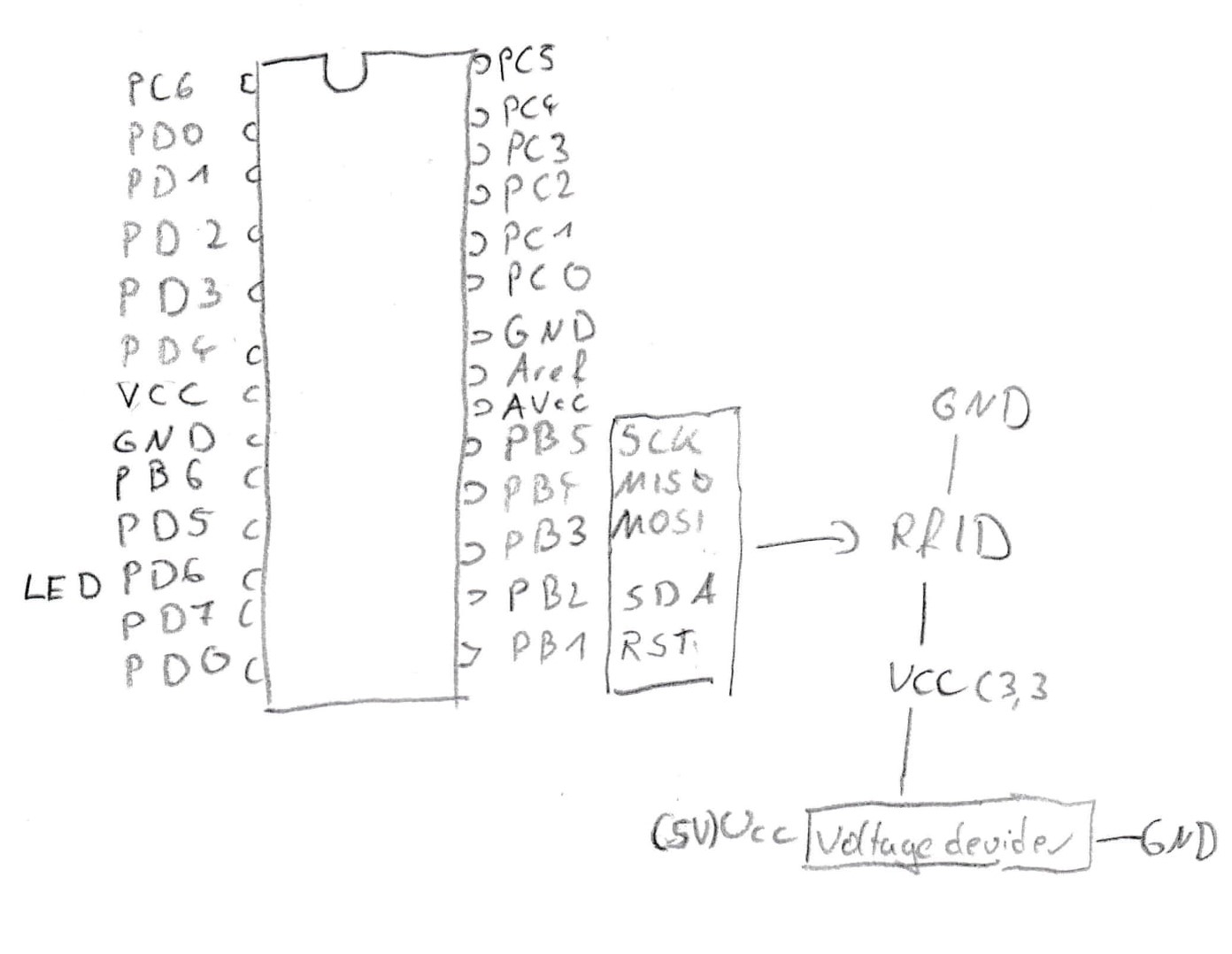
This is how you connect every cable to the fakeduino.
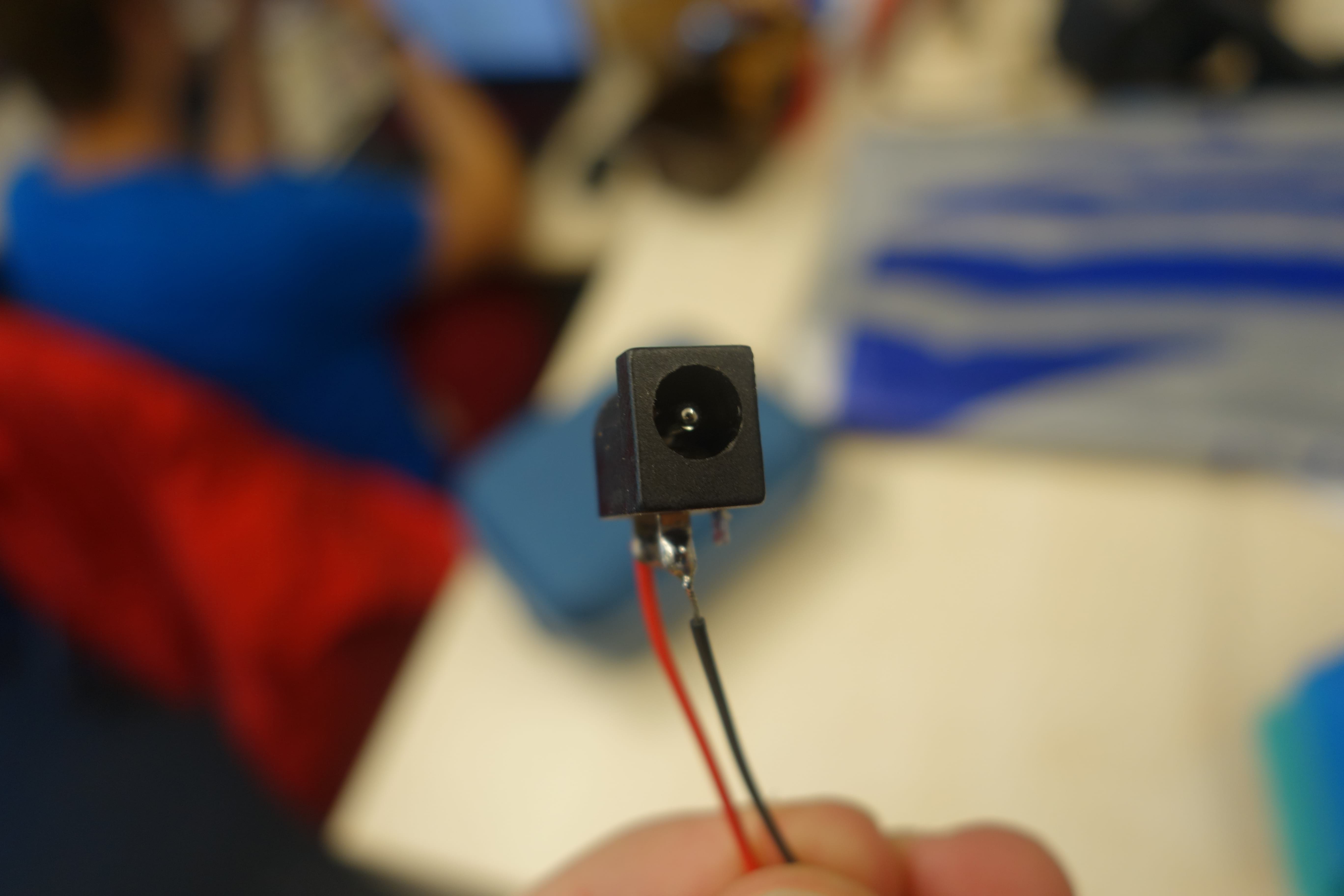
Here you can see the power plug, whether VCC or GND is in the middle depends on your charging cable so look it up in the manual.
In my case VCC was in the middle and GND on the outside.
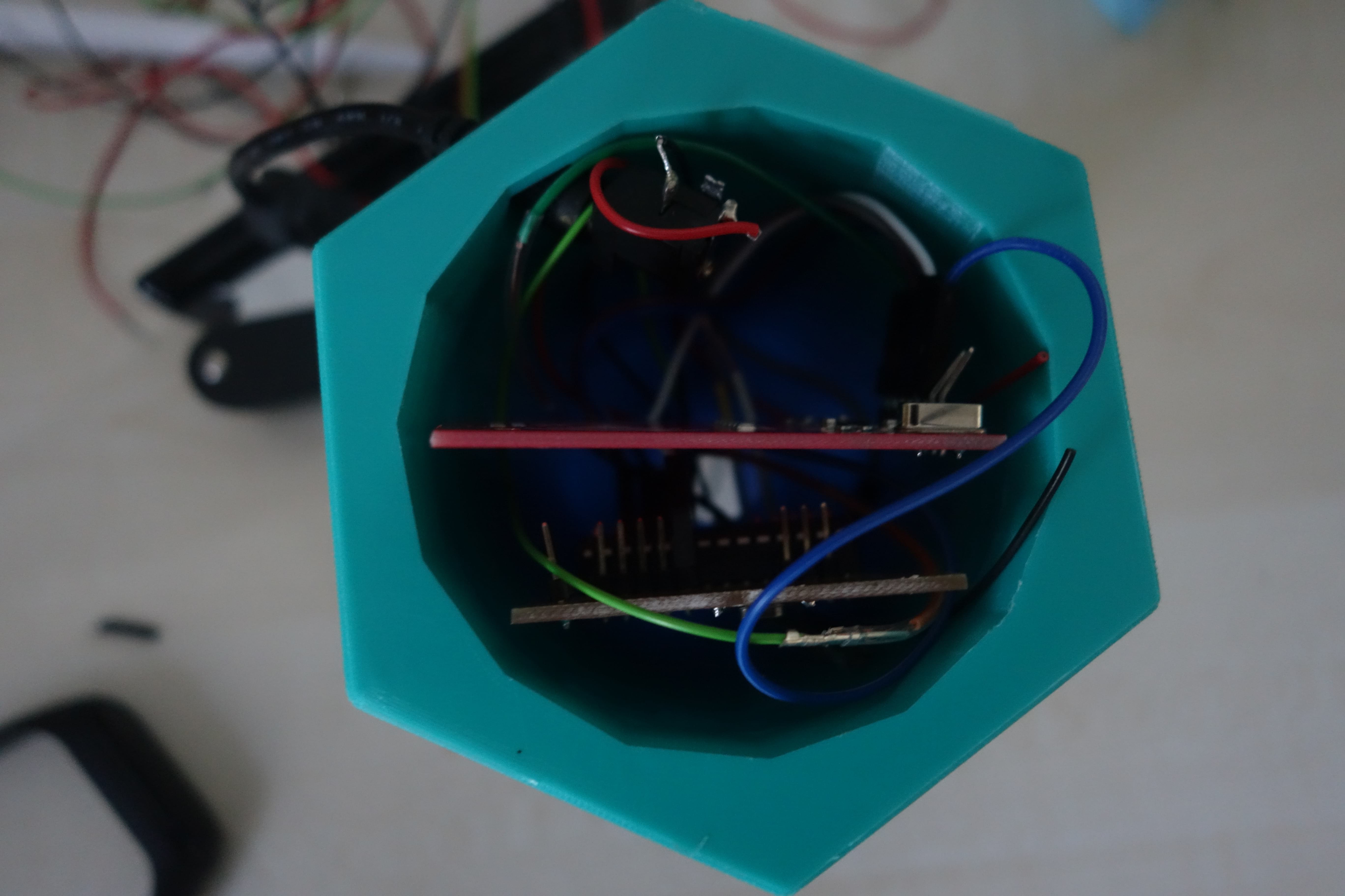
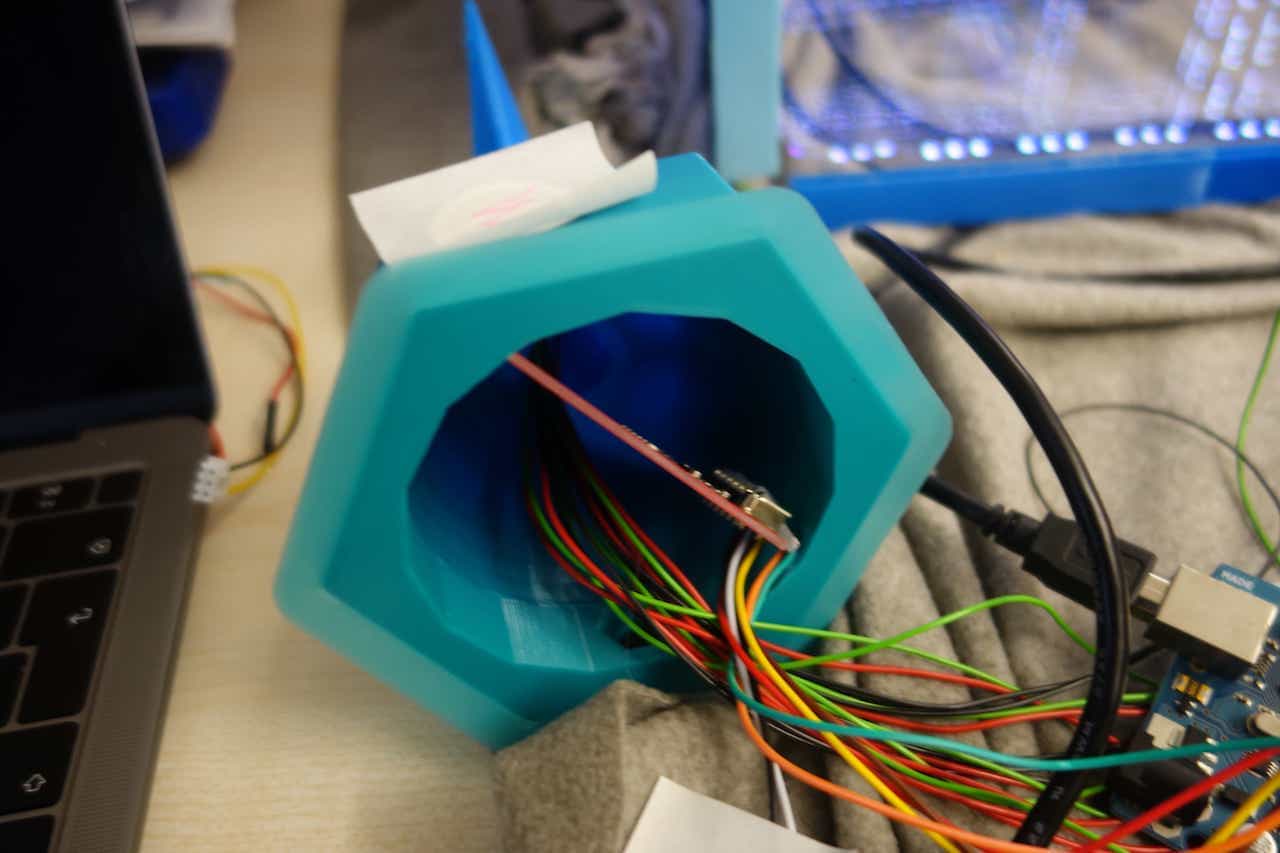
If you have connected every cable it should look like this. I shortened every cable and soldered the GND, VCC and
LED cables together to connect each to a single pin. The fakeduino is at the bottom so i does not obstruct
the RFID-sensor. At the top you can see the power plug if this makes any problems just put it next to fakeduino-board.
In my case it worked fine.
If I had to rebuild it it is maybe better to make a bigger base here everything is a tight fit.
If I had to rebuild it it is maybe better to make a bigger base here everything is a tight fit.

So the code creates "moving" groups of 3 illuminated Leds. It first overwrites the every Led-color so that
every Led would be turned off. Then it sets the colors of the Leds that should lights up the color saved in "curColor".
When that is done it displays the current state of the Leds using the "strip.show()" command. Now the program
waits for 200ms and then checks if a new RFID chips is present. If there is one it reads the data on it and
depending of what is read "curColor" is changed to white, blue or red. For debug reasons everything is dumped
into the serial as well.
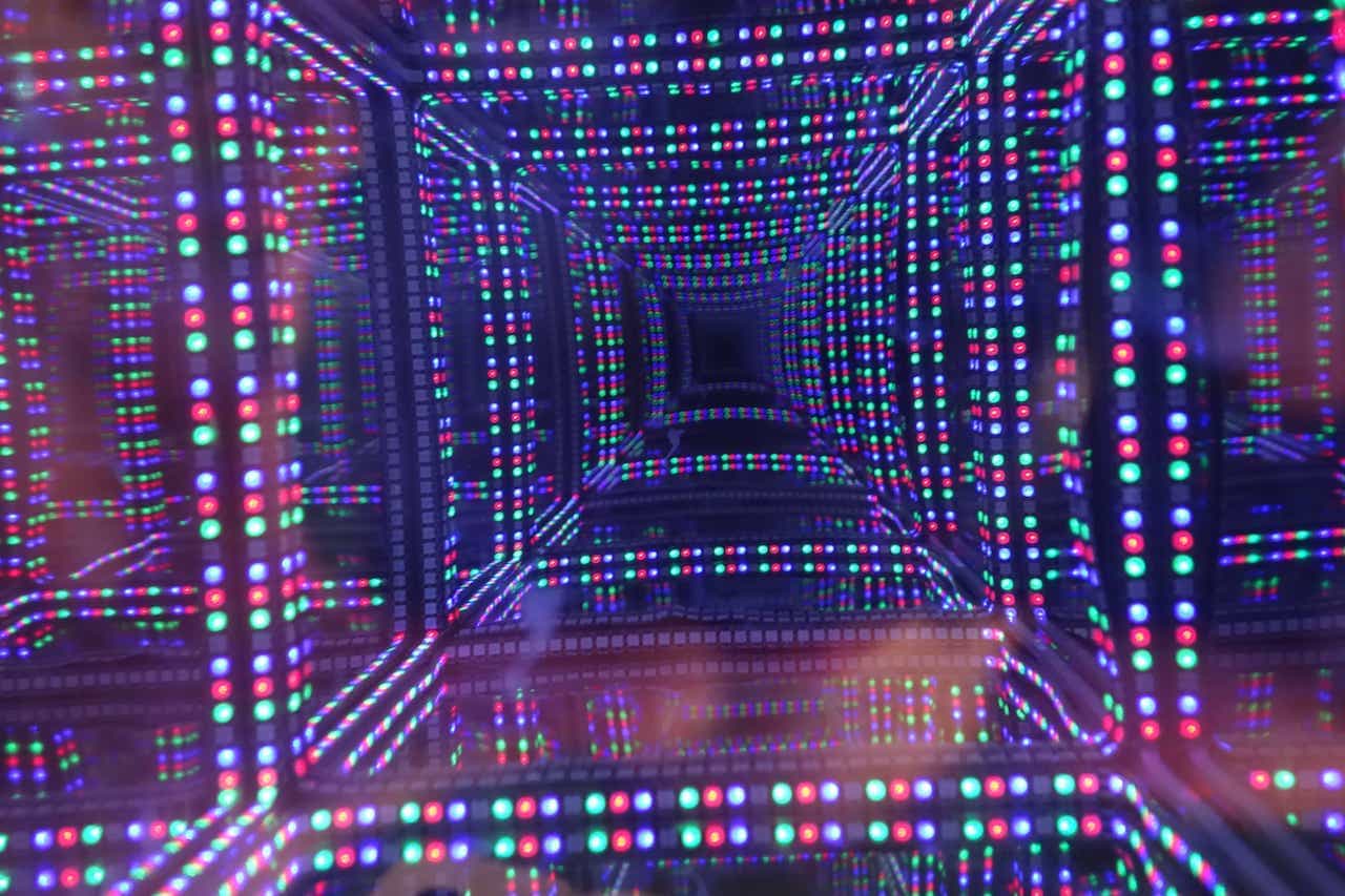
And that's it all that is now left to is shortening the wires turn off the lights and watch your Infinity cube

Since there space inside was not optimal and the base had no cover on the bottom I remade it.
Everything is the same except that the lower part is a little bigger and has spaces with clips for the fakeduino and the RFID-reader. They are clip-on since the most RFID-readers and the fakeduino have no holes to screw them to something. The power plug hole got a little bit bigger too, so you can now glue the 5V-Power plug inside of it.
These Files are marked with "V2" in the download section.