3. Computer-Aided Design
Assignment
- Model (raster, vector, 2D, 3D, render, animate, simulate, …) a possible final project, and post it on your class page.
2D Softwares
Vector vs Raster
Before starting It was important to learn about “vector” and “raster” files. There are two types of digital graphics- vector and raster. Vector images are made of pixels of hundreds of thousands of tiny lines and curves to create an image. Raster images are composed of pixels.
You can identify a vector image by looking at its edges. A vector image will always appear smooth no matter how large you make it or how close you zoom in. Text is one of the most common types of vector image. No matter how much you increase a font’s size, for example, its look never changes. Vector images are the most used options for creating logo or illustrations.
Raster images are often called bitmap images because they are made of millions of tiny squares, called pixels. you can identify a raster or bitmap image by looking at it very closely. If you zoom in enough, you will be able to see the square outlines of each pixel.
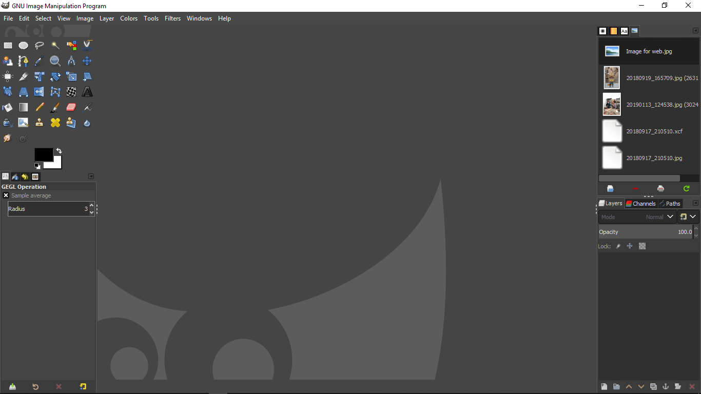
GIMP
GIMP is a free open source raster graphics editor used for image retouching and editing. I downloaded GIMP from here.
-
The user interface is somewhat similar to Adobe Photoshop.
-
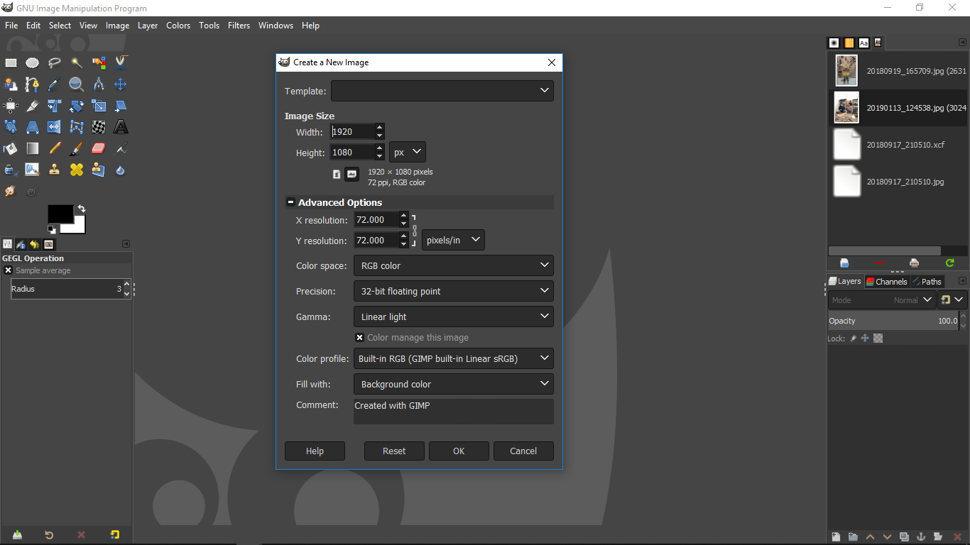
To create a new image, Go to File-> New.
-
Here you can select the size of the image, image resolution and background color(For PNG images, select Transparency option).
-
Resolution - X and Y resolutions are the resolution for the final image. 300 ppi is best for printers but for digital displays, 72ppi is better. This is important as there’s a difference in printing images on paper and displaying image on a digital screen. So, when you are displaying image on your website you want to compress image without being a noticeable quality loss because site speed and size of the webpage affects your SEO rankings on google which will affect overall traffic.
-
Precision is the precision with which images process when you use GIMP. If your PC is slow, then use lower precision. 32-bit floating point is for high-end machines.
-
Undo History in GIMP is somewhat similar to version control. you can switch to any version by clicking that on that version.
-
In GIMP, there are various tools that can be used for the combination of things include image editing, drawing, creating selection areas, manipulating, moving objects, adding texts, coloring areas and a lot of things.
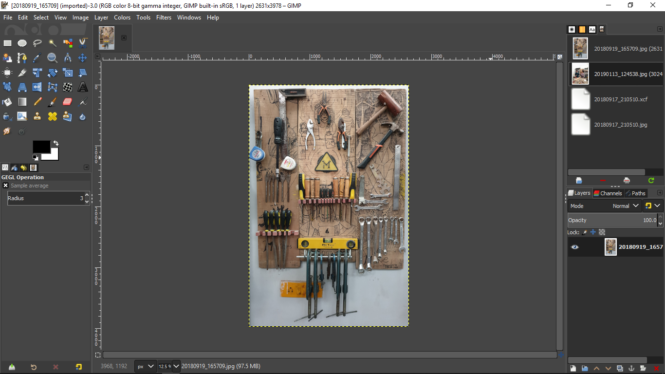
How to resize an image.
After playing with various tools, using the software was really easy for me.
- I tried to change the size of an image whose actual size was 5MB.
Steps
-
Open the image (File->open).
-
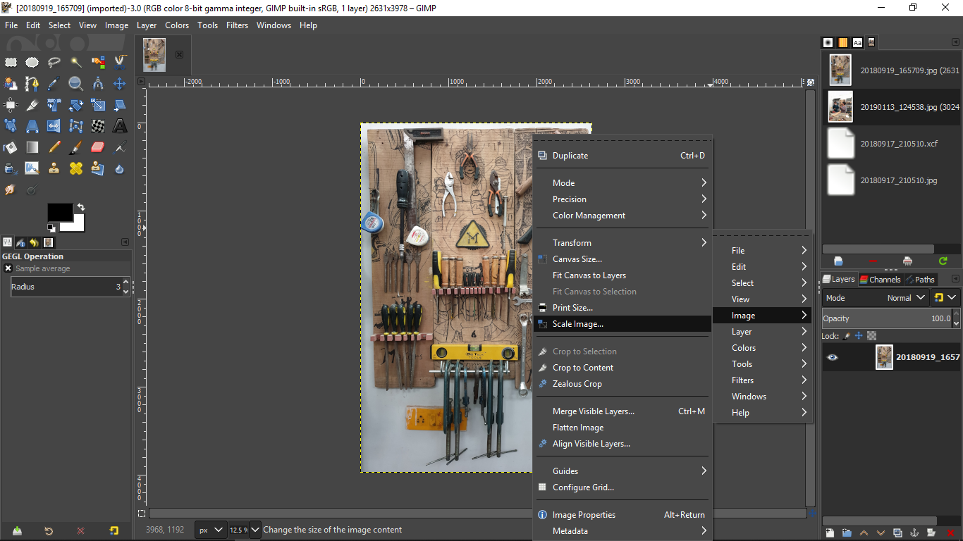
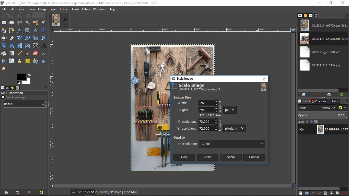
Right click on the image and select scale image-> image.
-
In the pop-up window, we can change the size and resolution of the image.
-
Export the image, Go to File-> Export.
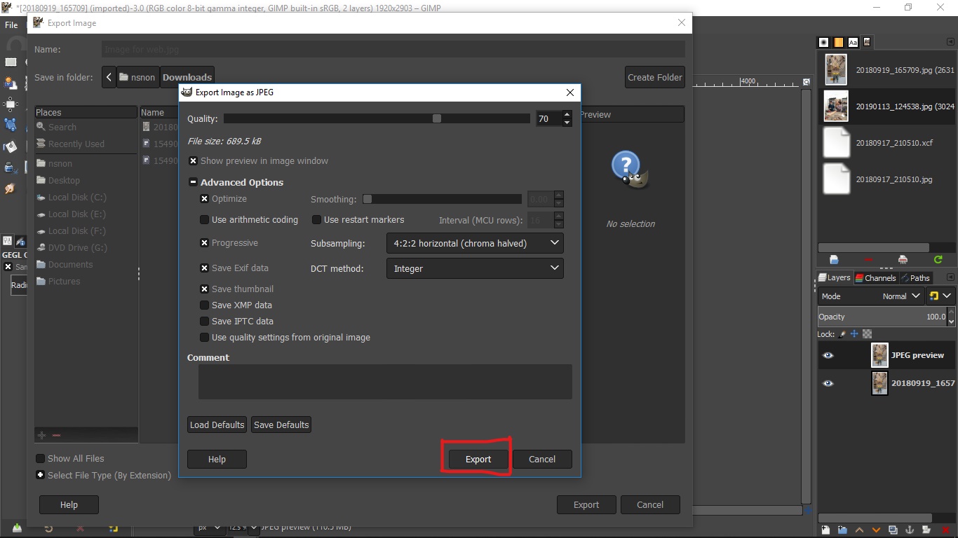
-
Here you can change the quality of the image to decrease image size and also try various options.
This reduced the size of the image from 5MB to 685 KB

Vector tools
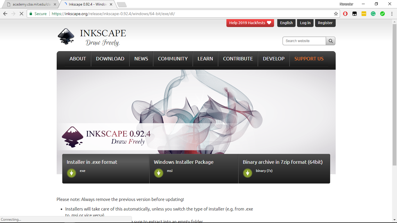
I already knew CorelDraw and Adobe Illustrator so I chose Inkspace for vector drawings.
- To download the software go to Incscape website and download according to your operating system.
Fun Fact: While it was installing I was working on another window and after installation, I switched the window to inkspace and I was like “why the hell I opened CorelDraw”:o. It was because the interface of CorelDraw and InkSpace look almost similar.
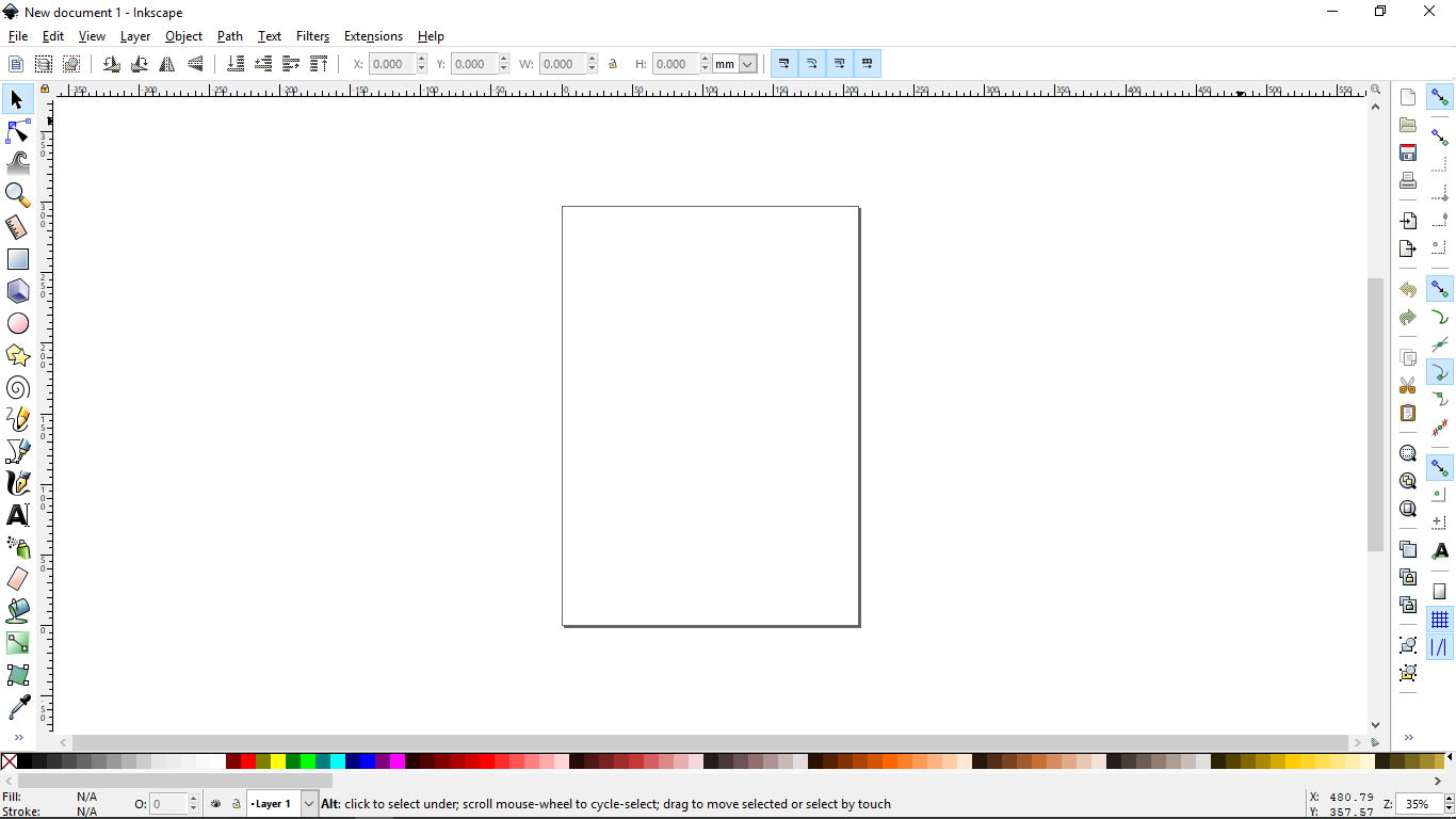
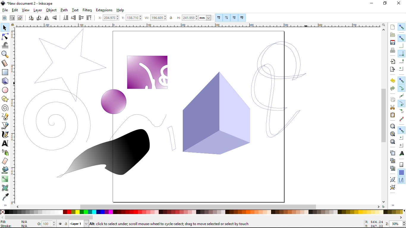
- I tried some tools to check their functions. It didn’t take too much time for me to understand most of the basic tools. After testing various tools I came to know that except one or two tools(“Create 3d boxes”, “Draw calligraphic strokes” etc.) everything is the same as is in CorelDraw.
Tracing a bitmap in InkSpace
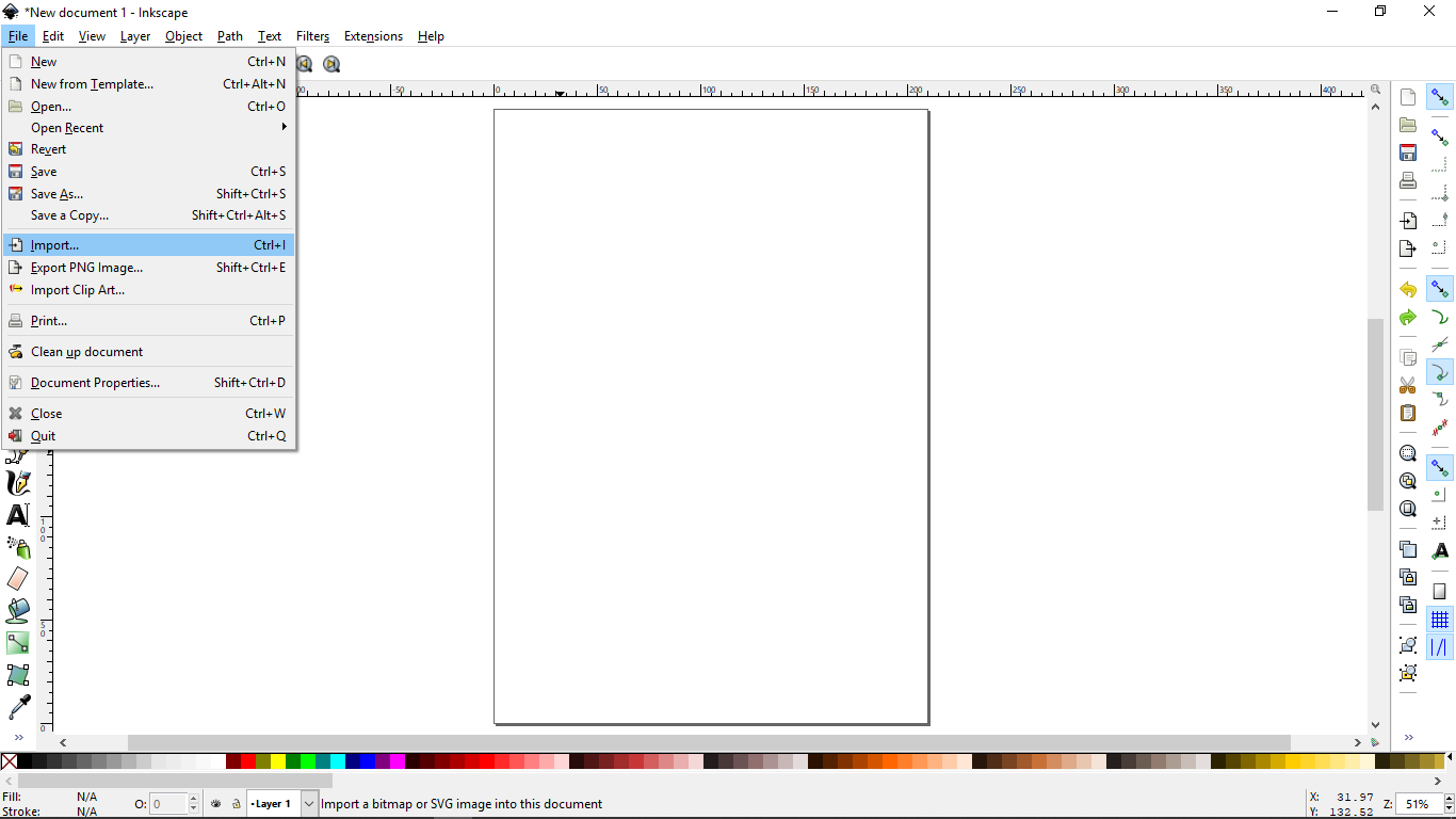
- Import the image (File->Import).
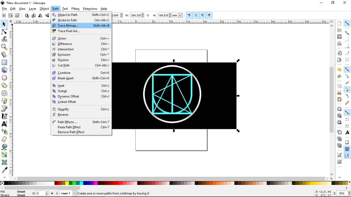
- Trace bitmap (Path->Trace bitmap).
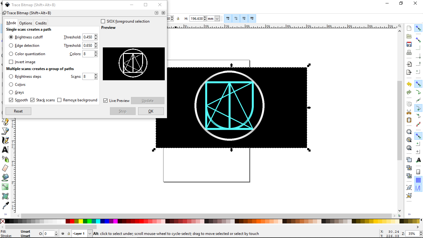
- In the window, you can set threshold values for tracing. I used o.450 as brightness cutoff.
- Next, break apart all the objects (Path-> Break apart).
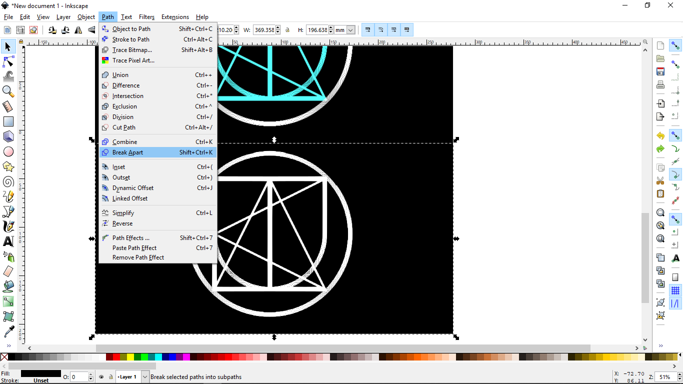
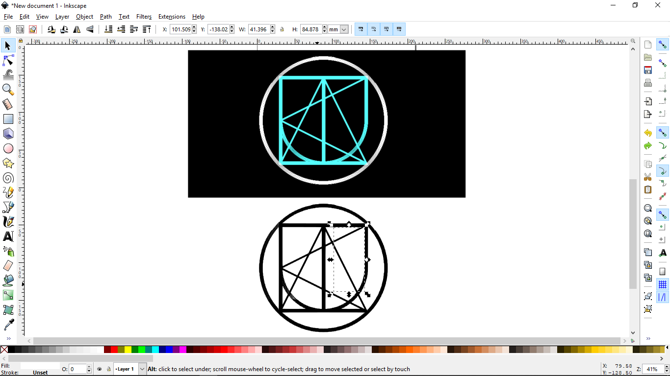
- Now, the image has been converted into vector.
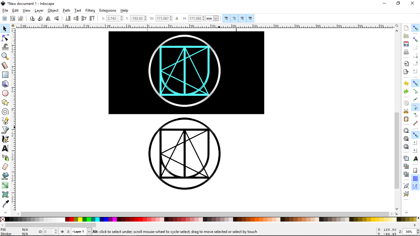
- You can check by selecting different objects.
Comparisons
-
InkSpace is free software and easy to learn and work with. If you are just starting to learn any vector software then InkSpace would be the best option. It has fewer CPU demands and can run smoothly on low-end computers. Also, it works on all operating systems. But there are some limitations too with this software, It doesn’t have the ability to output files in a CMYK-color format, making InkSpace, not a very good choice for designing anything needing to be printed.
-
Coreldraw is advanced software for designing vector files. It is mostly used for designing signs and banners as it has a much larger canvas than illustrator. Also, unlike InkSpace CorelDraw allows you to create print-ready files in CMYK format as Illustrator does, but without its price tag(It’s cheaper than Illustrator). The only disadvantage I know about this software is that it runs only on Windows.
-
Illustrator is the industry standard for vector design, there’s more upside to learning it over any other vector application. In Illustrator you can work on multiple artboards. Work on digital graphics can be done very easily. One thing I love about Illustrator is vector graphics created with Illustrator can be imported easily into other software.
3D Time
In the lecture Neil talked about various file extensions of 3D models(.step, .obj etc.) I had heard about all formats before but I didn’t know what’s the difference in these formats and why we have these many formats at first place. So, I researched about different file formats of 3D models.
Below is the description of each file extension.
DXF
DXF is short for Drawing Interchange Format or Drawing Exchange Format. Commonly known as AutoCAD DXF format, is a CAD data file format. It was developed by Autodesk to enable data interoperability between AutoCAD and other programs. DXF file format was first introduced in 1982. The key purpose of this format was to produce the exact representation of AutoCAD native DWG files on other applications. For many years, the importing process of DXF files had been very difficult because of the unavailability of specifications of the format. Presently the format specifications are available as PDF but this format is rarely used in AutoCAD applications.
STL
An StL (“StereoLithography”) file is a triangular representation of 3-dimensional surface geometry. The surface is tessellated or broken down logically into a series of small triangles (facets). Each facet is described by a perpendicular direction and three points representing the vertices (corners) of the triangle. These data are used by a slicing algorithm to determine the cross sections of the 3-dimensional shape to be built by the fabber.
OBJ
OBJ (or .OBJ) is a geometry definition file format first developed by Wavefront Technologies for its Advanced Visualizer animation package. The file format is open and has been adopted by other 3D graphics application vendors.
The OBJ file format is a simple data format that represents 3D geometry alone — namely, the position of each vertex, the UV position of each texture coordinate vertex, vertex normals, and the faces that make each polygon defined as a list of vertices, and texture vertices. Vertices are stored in a counter-clockwise order by default, making an explicit declaration of face normals unnecessary. OBJ coordinates have no units, but OBJ files can contain scale information in a human-readable comment line.
STEP
STEP-File is the most widely used[citation needed] data exchange form of STEP. ISO 10303 can represent 3D objects in Computer-aided design (CAD) and related information. Due to its ASCII structure, a STEP-file is easy to read, with typically one instance per line.
IGES
The Initial Graphics Exchange Specification (IGES) (pronounced eye-jess) is a vendor-neutral file format that allows the digital exchange of information among computer-aided design (CAD) systems. Using IGES, a CAD user can exchange product data models in the form of circuit diagrams, wireframe, freeform surface or solid modeling representations. Applications supported by IGES include traditional engineering drawings, models for analysis, and other manufacturing functions.
Almebic
Its primary focus is the interchange of geometry (models) between different groups working on the same shots or the same assets. This is often different departments in the same company or different studios working on the same projects. Alembic supports the common geometric representations used in the industry, including polygon meshes, subdivision surface, parametric curves, NURBS patches, and particles. Alembic also has support for transform hierarchies and cameras. With the latest version comes initial support for materials and lights as well. Alembic is very specifically not concerned with storing the complex dependency graph of procedural tools but instead stores the “baked” results.
CAD Softwares
I started with Sketchup, then tried Fusion360 and after that openSCAD.
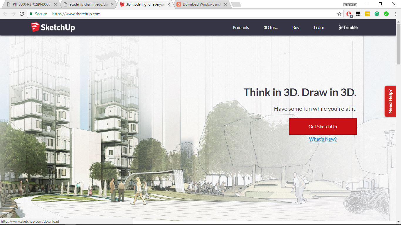
SketchUp
I watched these video tutorials before starting SketchUp. After watching tutorials, It was easy to work with the software and I figured out that it is the easiest software for CAD modeling.
Downloading and installation
- To download SketchUp, go to their official website.
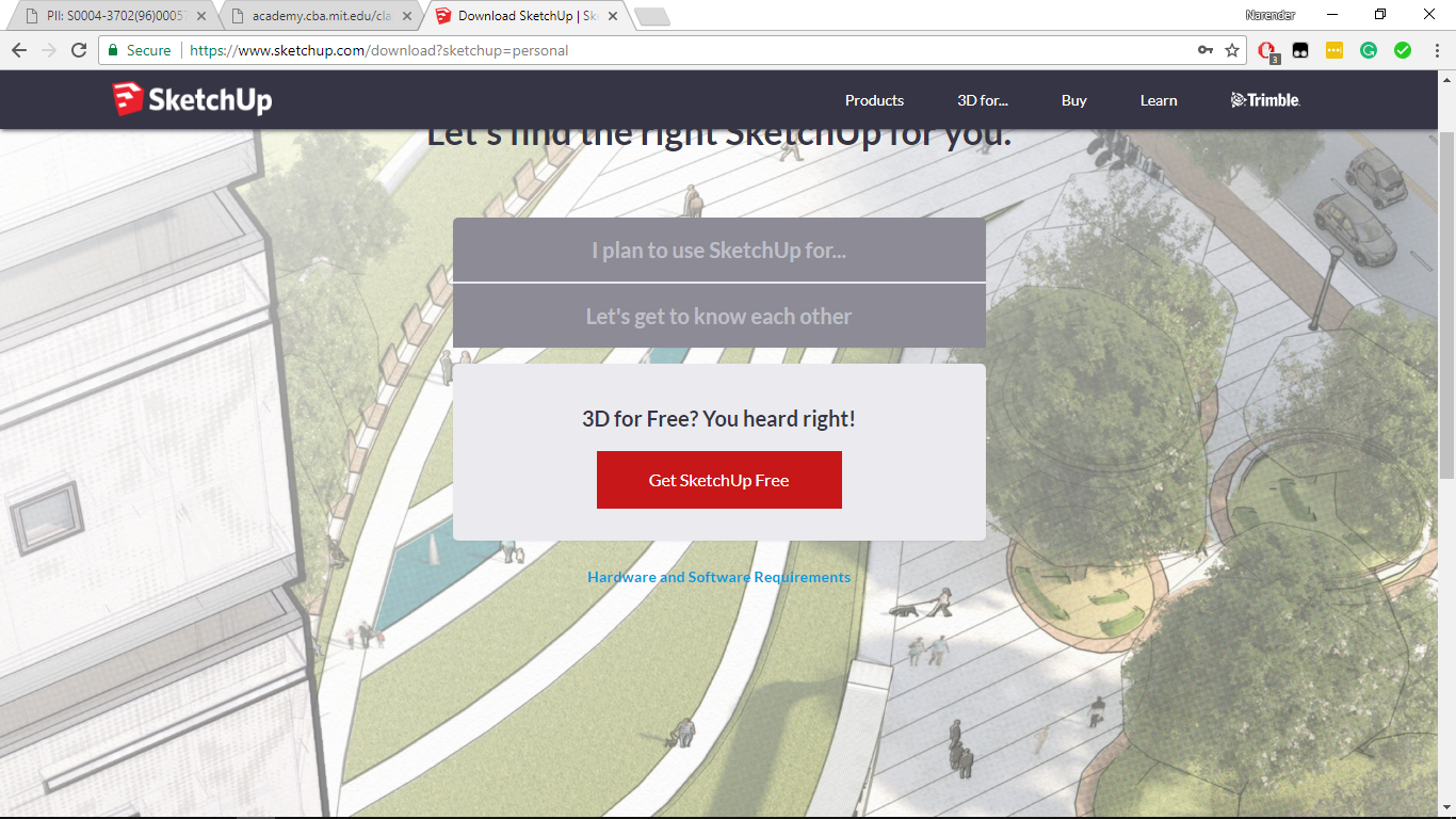
- Select the plan to use sketchup for.
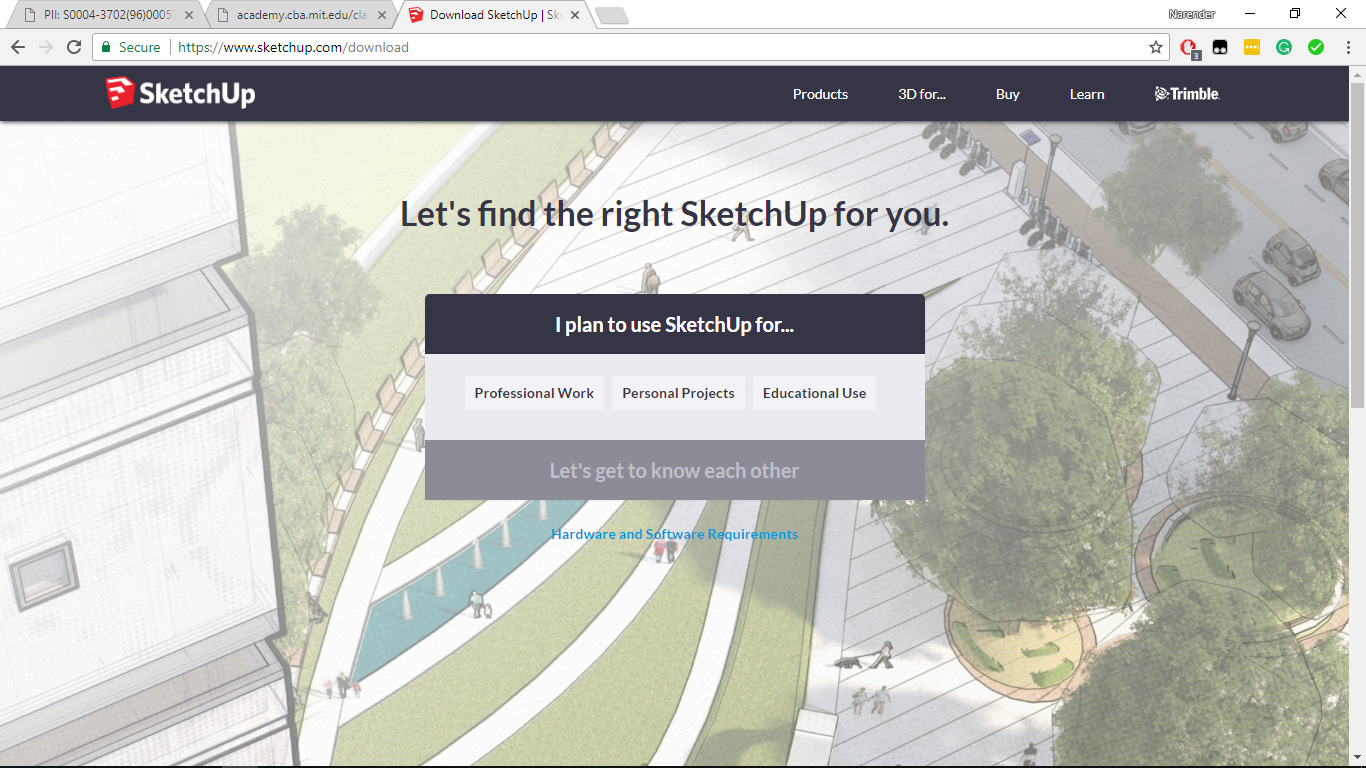
- Then create an account on “Trimble”. you can also sign in with google account.
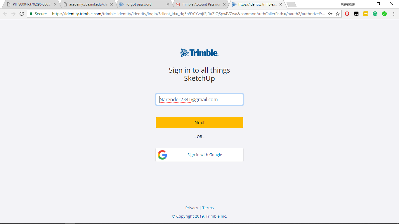
- Download and Install.
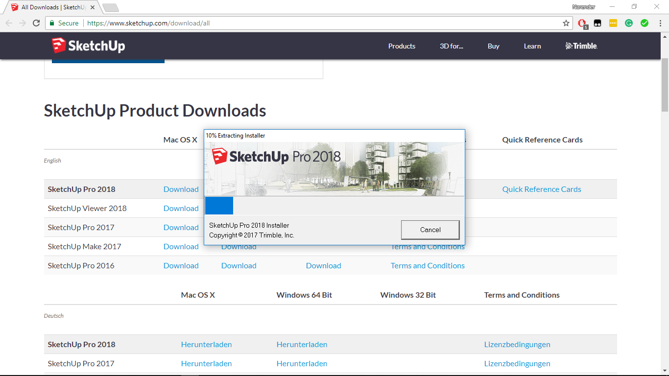
To start, one has to make a Trimble account, then it can be used in the web browser and also can be downloaded as an application for all operating systems.
-
The UI of SketchUp is very simple and one can easily start working in SketchUp.
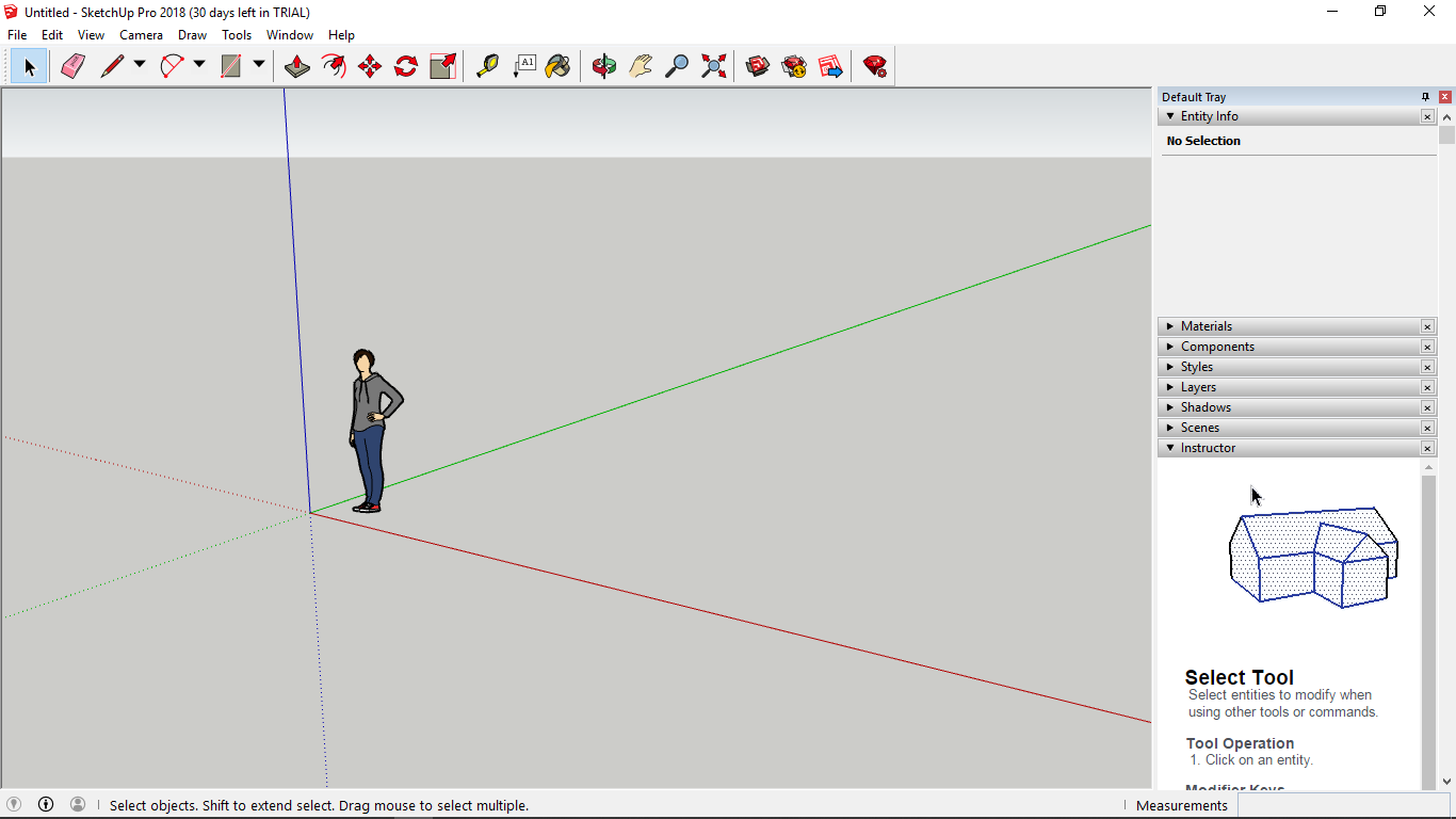
-
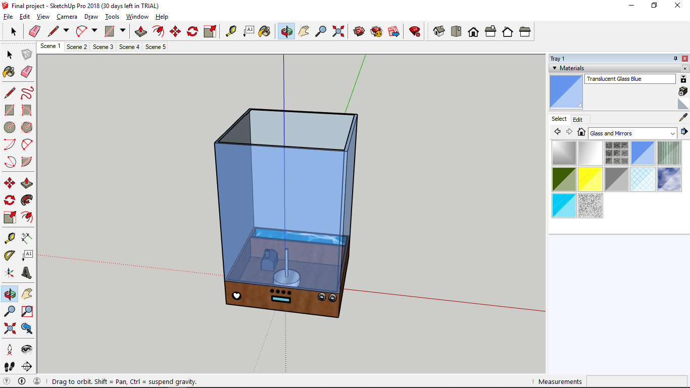
Then I tried to model my final project. This is not the detailed version but just to give an idea how it would look like.
Learning outcomes from SketchUp
- It was really easy to use this software, I used this software for the first time, still, I was able to model some parts of my final project.
- Here you don’t have to select a plane every time you want to sketch something, It automatically detects plane when you hover over any surface.
- I liked the animation feature in the software.
- I figure out that this software is mostly used for architectural models.
Fusion360
- To download Fusion360, go to their official website.
- Create an Autodesk account. Autodesk provides 3 years of free license for students.
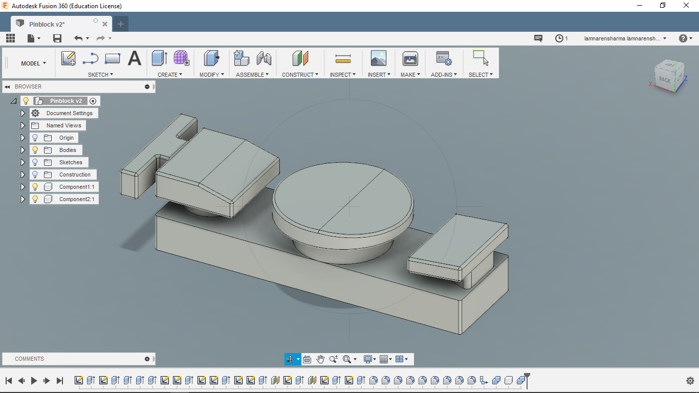
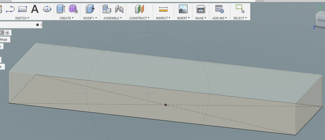
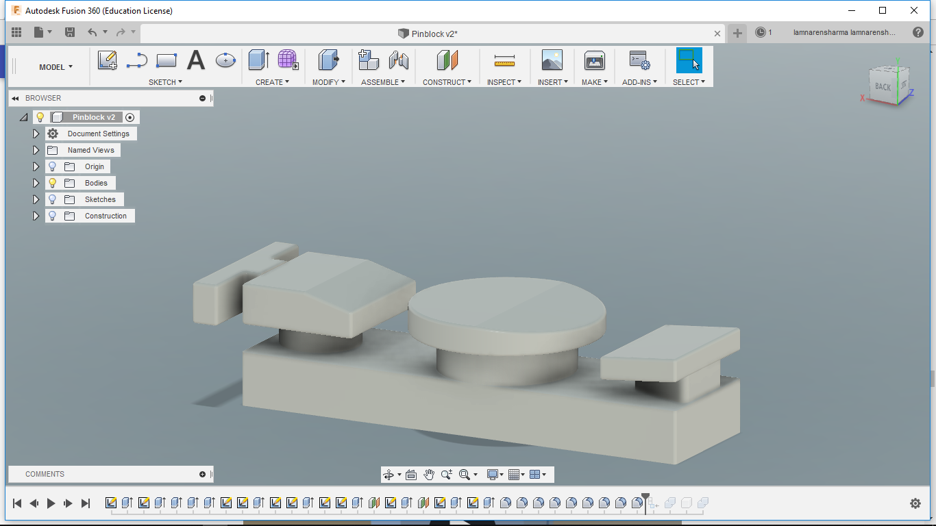
After SketchUp, I tried Fusion360. I already knew how to use Fusion360. So, I opened Fusion and started to model whatever I had on my table at that time. And the outcome is worth sharing :p
Steps
-
Go to sketch –> rectangle and create a rectangle choosing the xy plane.
-
Click on create –> Extrude, and then extrude the created rectangle to 10mm
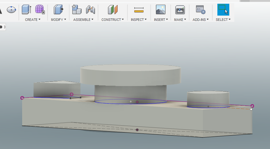
-Again go to sketch and select center diameter circle and draw two circles. Also, selecting line tool, create a quadrilateral at the left.

-
Go to create–>. Extrude and extrude all three sketches.

-
Then again create and extrude a circle on the top of the center circle.
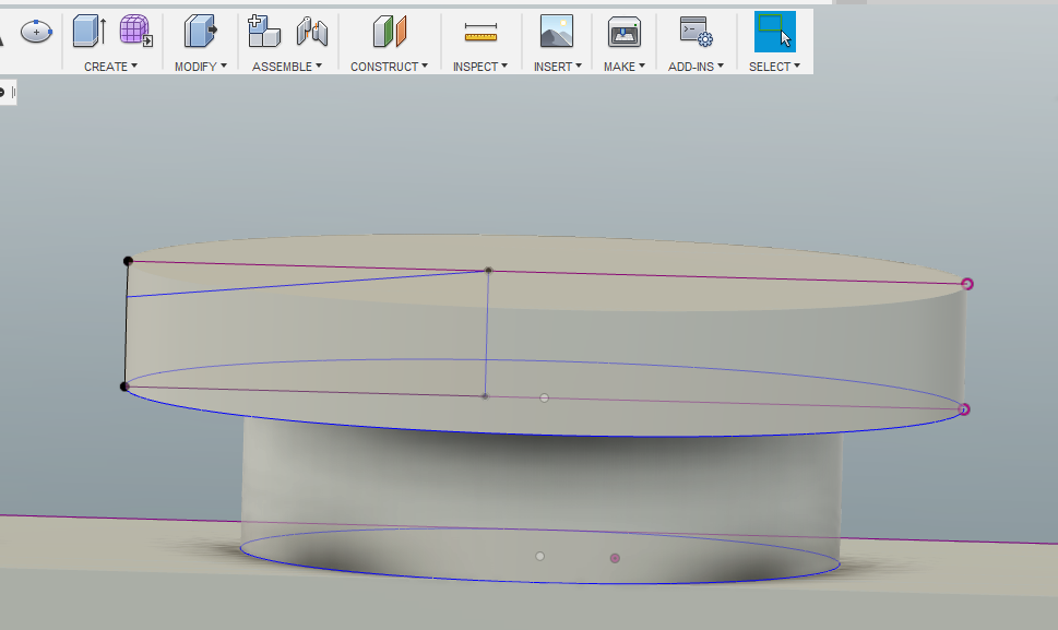
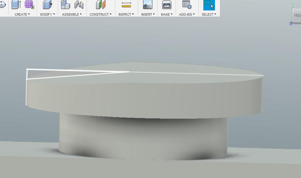
-
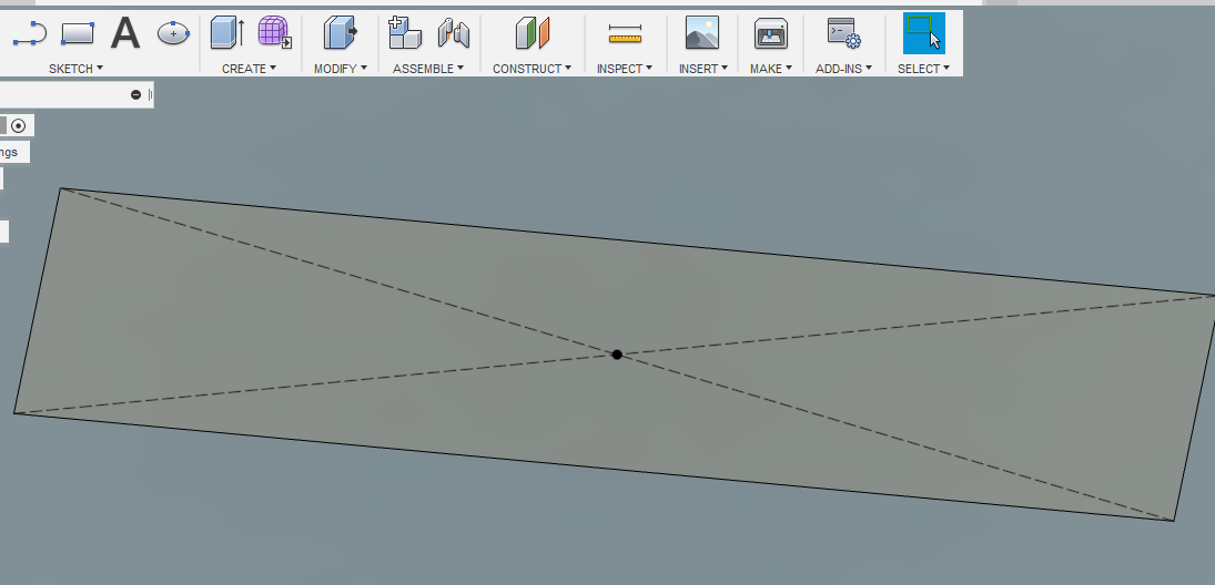
Here, I needed to taper the top circle. So on the xz plane I drew a quadrilateral and rotate it to 180degree and selected mode to cut instead of join.
-
Again, draw a quadrilateral in xz plane on the rightmost circle and extrude it to 20 mm both side.
-
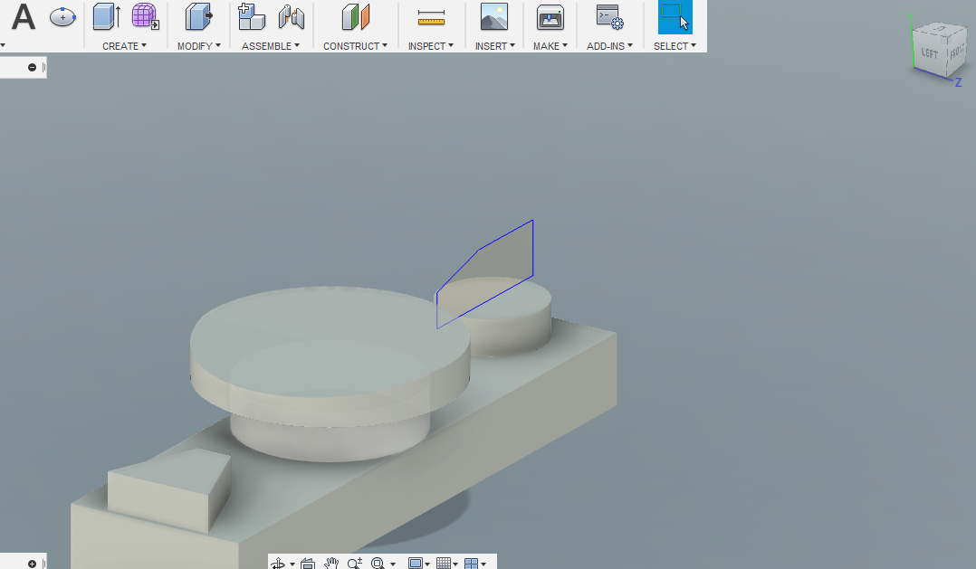
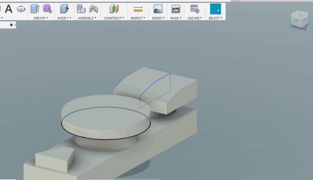
Go to construct–> offset plane and create a plane above 20 mm to the base. and using line tool draw the sketch showed in the picture. Next, extrude it to 15 mm.

-
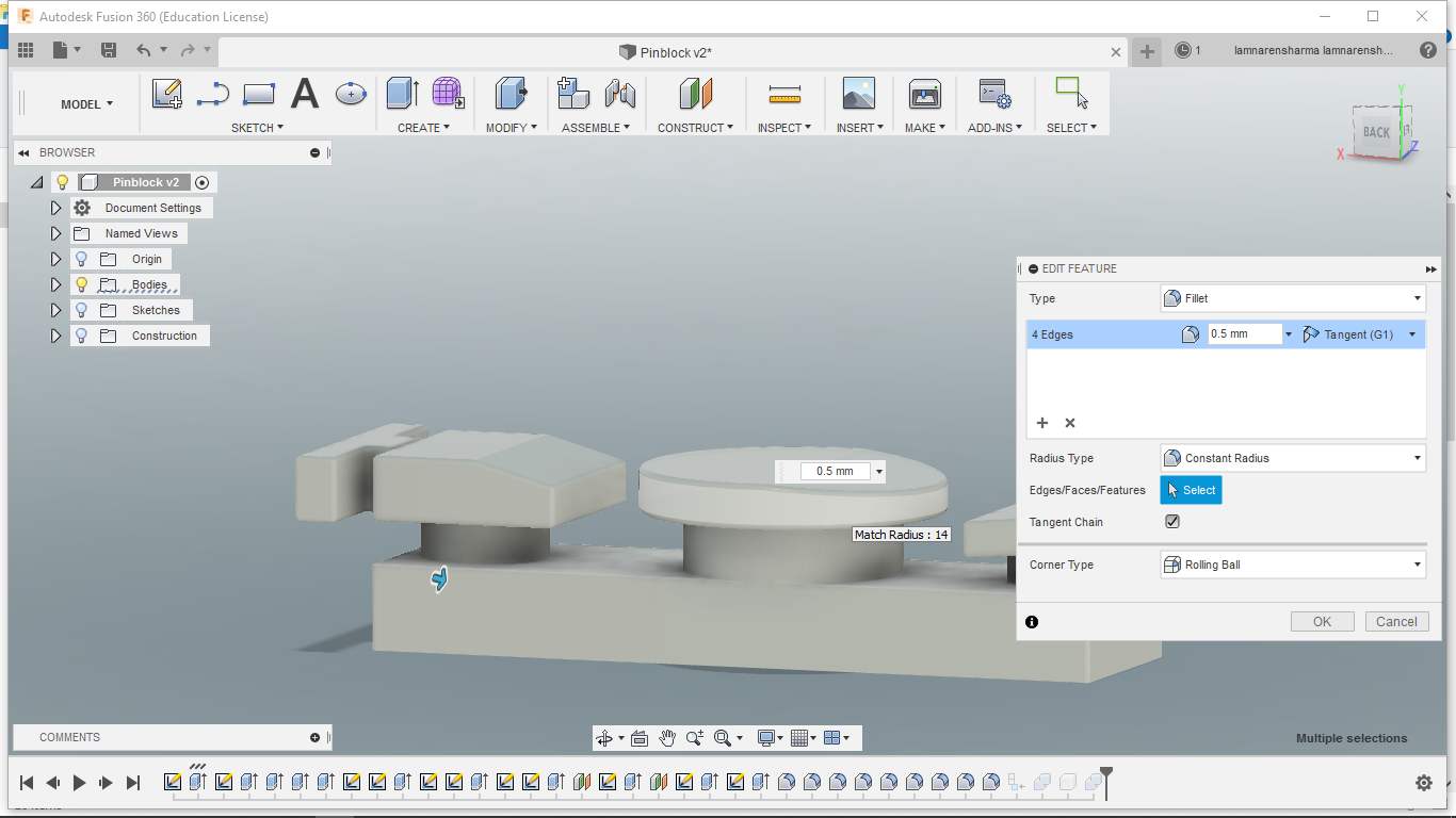
Lastly, Go to Modify–>fillets and add select all the edges in the design and fillet them to 0.5mm to make them a lil bit rounded.
Learning outcomes from Fusion360
- Fusion is free software(For students and startups) still very powerful for CAD modeling.
- Sculpting is one of the great features of this software.
- I also liked the timeline feature, with this you can go back at any step, make some changes there and all subsequent steps updates automatically.
OpenSCAD
OpenSCAD is an open source free CAD modeling software. In this, you can make complex figures using the intersection, union, subtraction etc. of basic geometrical shapes. For me, this was a new experience as I never designed anything before using programming. But it was fun to do this. I followed these tutorials.
- First I tried to model basic shapes like Sphere, Cylinder etc.
- Next, I learned how to do union, subtraction, intersection etc.
- Then I tried to move places from one position to another.
- Here you can find some important commands for OpenSCAD.

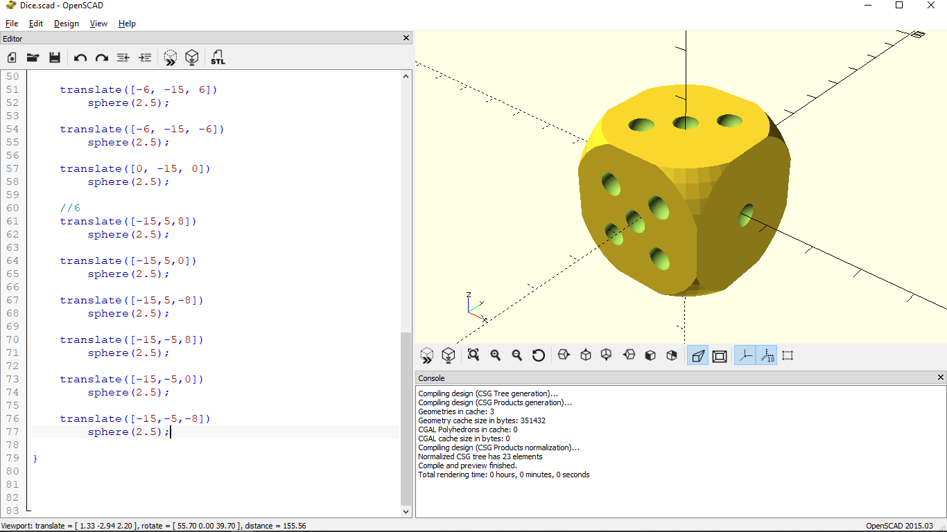
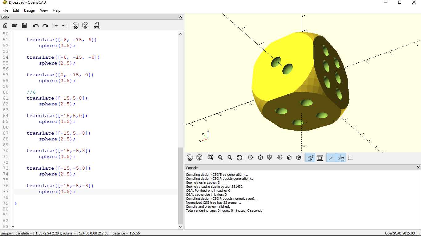
After learning some basic commands, I wanted to make dice.
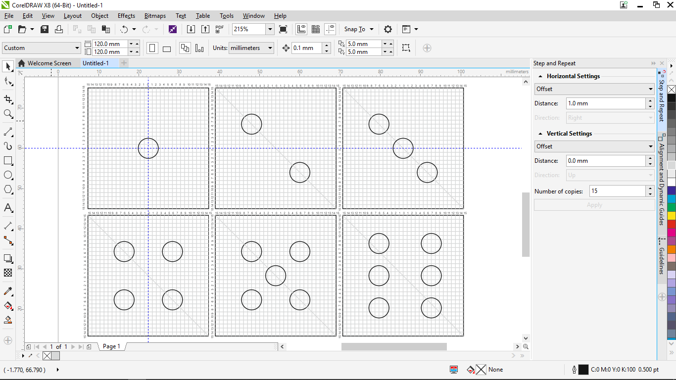
-
To start, I needed to do some mathematical calculation to get coordinates of all dots. So, I used CorelDraw this time instead of InkSpace to create the 2D graphical representation of dots because for me it was easier to work with CorelDraw.

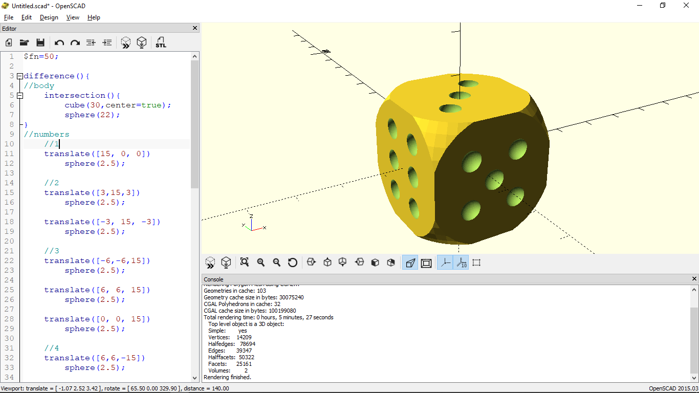
-
Final outcome in OpenSCAD-
Steps
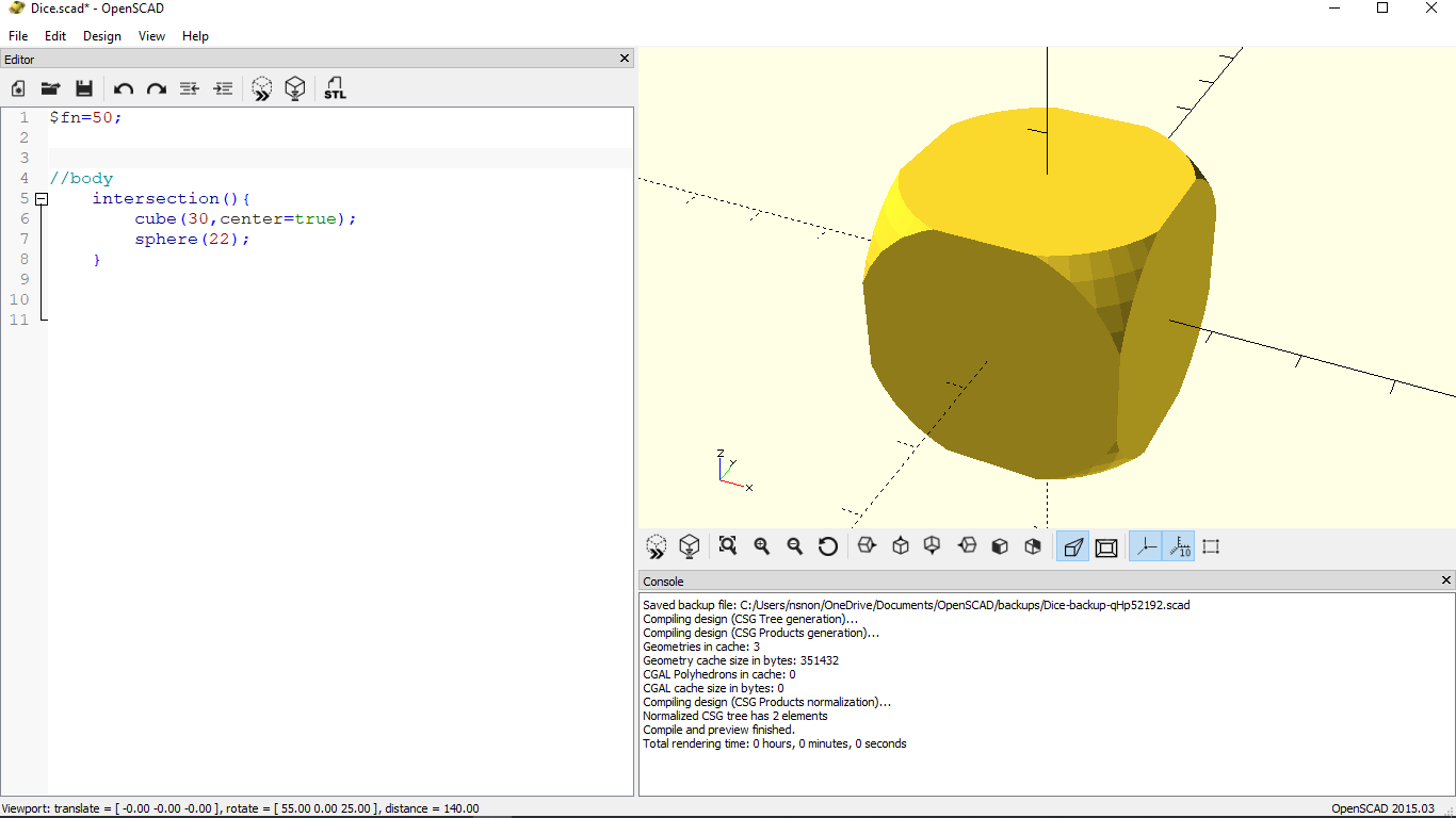
-
First, I created a cube of side 30cm and sphere of diameter 22. then did the intersection of both to get the rounded corners of the cube.
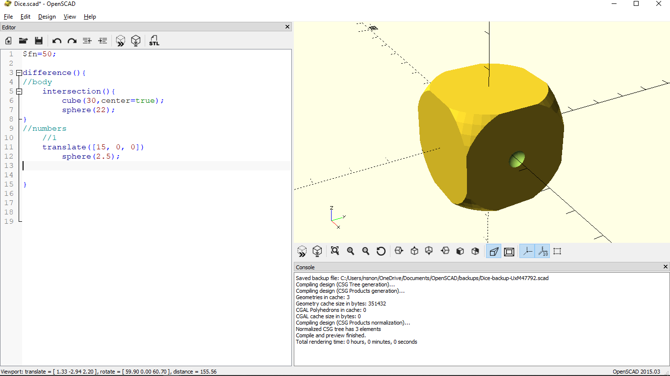
-
To create number 1, I made a sphere of 2.5cm and move the center of it on to the one face of the cube. then, subtract this sphere from the cube to get a cavity on the face.
-
I repeated the 2nd step to get the numbers 2 to 6 on the faces of the dice. I just made the sphere at different positions and moved them on their respective faces.
Here You can download all the design files.
Inkscape tracing
Learning outcomes from OpenSCAD
- This software is something different from all other CAD software.
- To model in this, one needs to work on mathematical computations and graphical representations.
- Programming is always fun as I have already mentioned in my previous assignments :)
Useful links
Tutorials
DESIGN is creativity with Strategy

This work is licensed under a Creative Commons Attribution-NonCommercial-ShareAlike 4.0 International License.