12. Output devices
Assignment
-
Individual assignment:
Add an output device to a microcontroller board you’ve designed, and program it to do something -
Group assignment: Measure the power consumption of an output device
Output Devices
An output device is any piece of hardware item which utilizes whatever data and commands from your microcontroller/processor in order to perform a task. This leads to the results of data processing carried out by an information processing system (such as a microcontroller) which converts the electronically generated information into human-understandable form.
Devices which perform an “Output” function are generally called Actuators and are used to control some external device
Common output devices

I decided to drive the stepper motor using ATtiny 44. The first step is to know about stepper motor, how it works.
Stepper motor
Intro
Stepper motors are different from all other types of electrical drives in the sense that they operate on discrete control pulses received and rotate in discrete steps. On the other hand, ordinary electrical a.c and d.c drives are analog in nature and rotate continuously depending on magnitude and polarity of the control signal received. The discrete nature of the operation of a step motor makes it suitable for directly interfacing with a computer and direct computer control. These motors are widely employed in industrial control, specifically for CNC machines, where open loop control in discrete steps are acceptable. These motors can also be adapted for continuous rotation.
Construction
Stepper motors are normally of two types:
- (a) permanent magnet
- (b) variable reluctance type.
In a stepper motor, the excitation voltage to the coils is d.c. and the number of phases indicates the number of windings. In both the two cases the excitation windings are in the stator. In a permanent magnet type step motor the rotor is a permanent magnet with a number of poles. On the other hand, the rotor of a variable reluctance type motor is of a cylindrical structure with a number of projected teeth
Unipolar vs Bipolar motor
The unipolar stepper motor operates with one winding with a center tap per phase. Each section of the winding is switched on for each direction of the magnetic field. Each winding is made relatively simple with the commutation circuit, this is done since the arrangement has a magnetic pole which can be reversed without switching the direction of the current.
In bipolar stepper motors, there is only a single winding per phase. The driving circuit needs to be more complicated to reverse the magnetic pole, this is done to reverse the current in the winding. This is done with an H-bridge arrangement, however, there are several driver chips that can be purchased to make this a more simple task.
Wire connection diagram
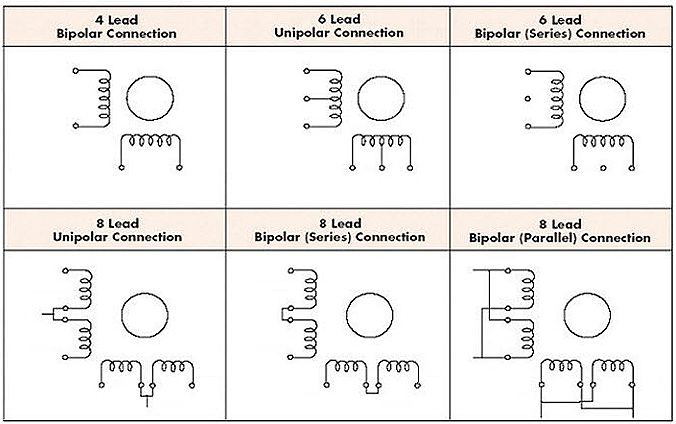
Let’s Start
I had a stepper motor Nema17. This is a unipolar stepper motor with 6 wires. I tried to test it first and control it using Attiny 44.
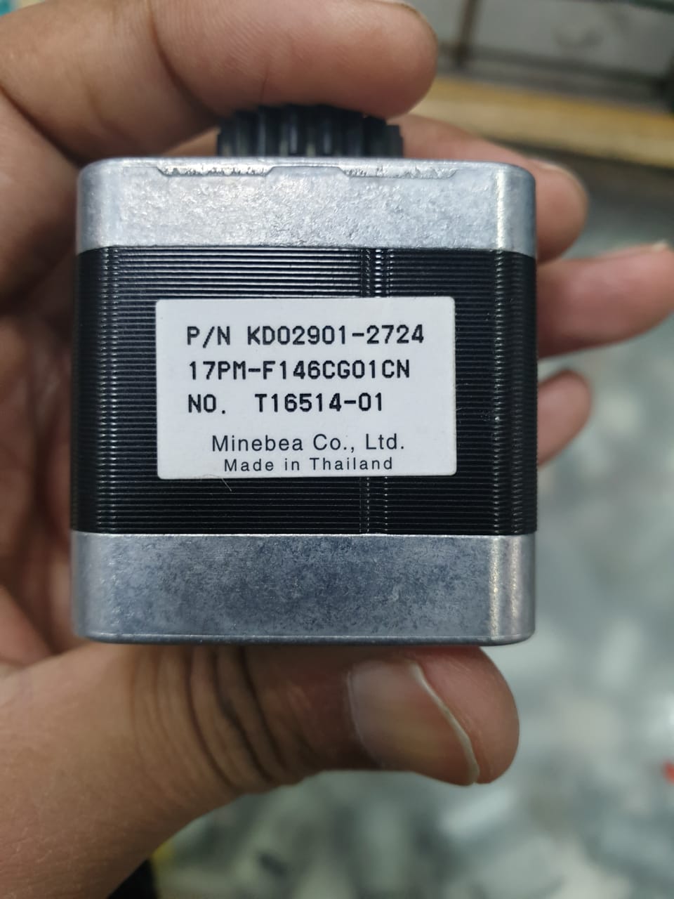
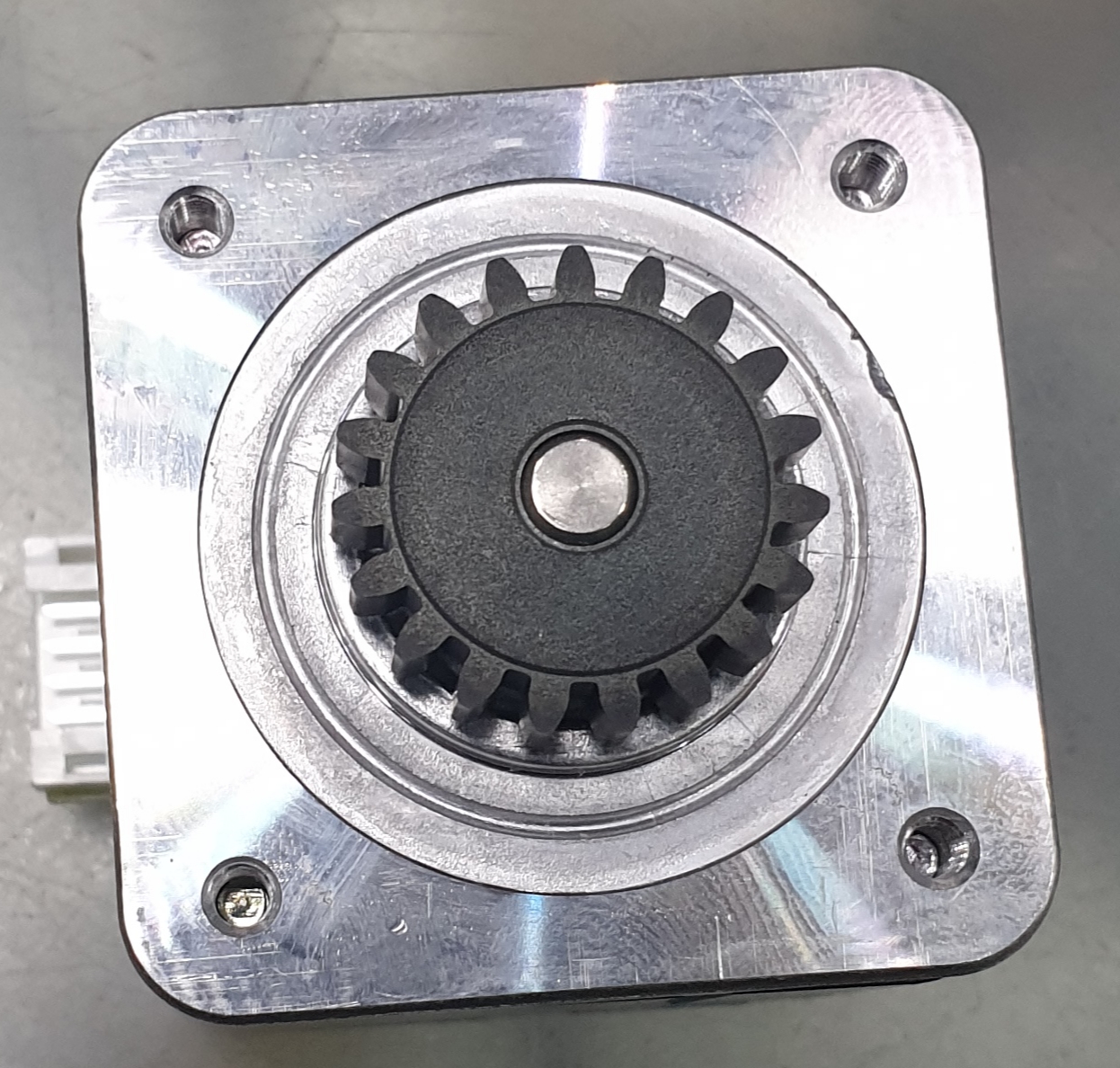
Testing of the motor
In 6 wire unipolar stepper motor, the first 3 wires belong to coil A and next 3 wires belong to coil B. Check the resistance between wire 1-2, 2-3 and 1-3. The resistance between 1-2 and 2-3 should be the same and double the resistance between 1-3. If it so then the winding of that coil is perfect. Repeat this step for other coils too.
Driver
I used DRV8825 driver from Polulu to drive my stepper motor.
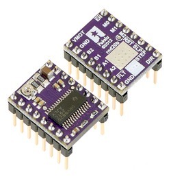
Some key features of this driver are:-
- Simple step and direction control interface
- Six different step resolutions: full-step, half-step, 1/4-step, 1/8-step, 1/16-step, and 1/32-step
- Adjustable current control lets you set the maximum current output with a potentiometer, which lets you use voltages above your stepper motor’s rated voltage to achieve higher step rates.
- Built-in regulator (no external logic voltage supply needed
Wiring digram
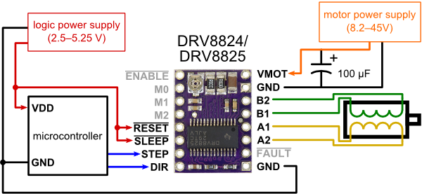
Step:- This is input is given as pulses, the frequency of which determines the rotational frequency of the motor, and the number of pulses corresponds to the number of steps. So if we need the stepper to move 10 steps, we just give 10 pules, and the rate at which we give the pulse determines how fast the stepper moves those 10 steps.
Dir:- This controls the direction in which the stepper moves. This pin can be High or Low, and obviously high and low corresponds to the CW and CCW rotations.
Then there are more pins which we could use or somehow bypass. Including
MS1, MS2, MS3 :- Micro-stepping selection
Normally low, could be set high as per the table to enable micro-stepping for higher resolution movements.
Enable:- (Normally Low) Setting this Pin High, will disable the FETs in the chip, killing the power to the motor.
Sleep:- (Normally High) Set this pin Low to put the chip in sleep mode to save power when the Motor/Chip is not in use.
Reset:- (Normally Floating) This is a floating pin and should be kept high to use the motor normally, when set low the motor shall return to the original position the motor was in when the chip was turned on. Should refer to the Data-sheet for more information. If this pin is low all STEP signals are ignored.
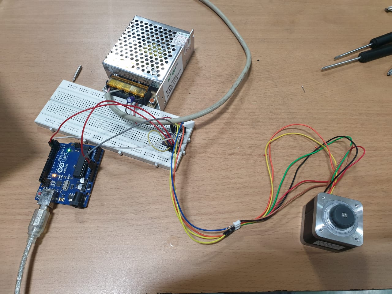
Testing on breadboard
I connected the driver, motor and the power supply(12V, 5A) according to the wiring diagram given above.
Code
#include <AccelStepper.h>

AccelStepper motor1(1, 32, 30);

void setup()
{
   stepper.setMaxSpeed(1000);
   stepper.setSpeed(50);
}

void loop()
{
   stepper.runSpeed();
}
Group Assignment
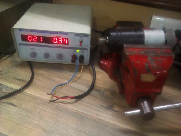
Our group assignment was to measure the power consumption of an output device. For this, we chose a dc motor and connected it to the variable power supply and observed the current drawn by the motor at different voltages.
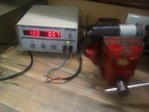
Observations
- The current drawn by the motor at 12volts is about 570mA and at 2.1 volts is about 340mA.
- To calculate the power, we used the formula P= VXI.
- Power consumption at 12 volts is, 12 * 0.570/1000 = 6.84 Watts.
- Power consumption at 2.1 volts is, 2.1 * 340/1000 = 0.714 watts.
- So the power consumed by the motor at No load ranges from 0.714 W to 6.84 W.
Speaker
I then also tested speaker to play some tunes using arduino.
A loudspeaker is an electroacoustic transducer; a device which converts an electrical audio signal into a corresponding sound. The dynamic speaker operates on the same basic principle as a dynamic microphone, but in reverse, to produce sound from an electrical signal. When an alternating current electrical audio signal is applied to its voice coil, a coil of wire suspended in a circular gap between the poles of a permanent magnet, the coil is forced to move rapidly back and forth due to Faraday’s law of induction, which causes a diaphragm (usually conically shaped) attached to the coil to move back and forth, pushing on the air to create sound waves. Besides this most common method, there are several alternative technologies that can be used to convert an electrical signal into sound. The sound source (e.g., a sound recording or a microphone) must be amplified or strengthened with an audio power amplifier before the signal is sent to the speaker. Speakers are typically housed in a speaker enclosure or speaker cabinet which is often a rectangular or square box made of wood or sometimes plastic. The enclosure’s materials and design play an important role in the quality of the sound.

Code
int speakerPin = 9;

int length = 15; // the number of notes
char notes[] = "ccggaagffeeddc "; // a space represents a rest
int beats[] = { 1, 1, 1, 1, 1, 1, 2, 1, 1, 1, 1, 1, 1, 2, 4 };
int tempo = 300;

void playTone(int tone, int duration) {
for (long i = 0; i < duration * 1000L; i += tone * 2) {
digitalWrite(speakerPin, HIGH);
delayMicroseconds(tone);
digitalWrite(speakerPin, LOW);
delayMicroseconds(tone);
}
}

void playNote(char note, int duration) {
char names[] = { 'c', 'd', 'e', 'f', 'g', 'a', 'b', 'C' };
int tones[] = { 1915, 1700, 1519, 1432, 1275, 1136, 1014, 956 };

// play the tone corresponding to the note name
for (int i = 0; i < 8; i++) {
if (names[i] == note) {
playTone(tones[i], duration);
}
}
}

void setup() {
pinMode(speakerPin, OUTPUT);
}

void loop() {
for (int i = 0; i < length; i++) {
if (notes[i] == ' ') {
delay(beats[i] * tempo); // rest
} else {
playNote(notes[i], beats[i] * tempo);
}

// pause between notes
delay(tempo / 2);
}
}
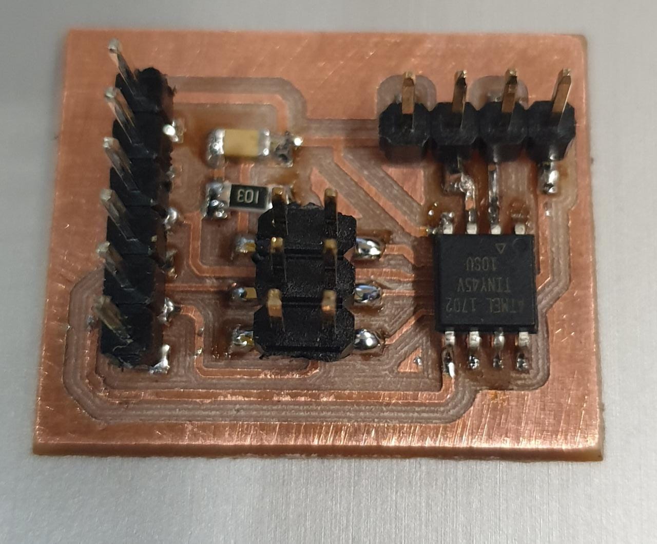
Schematic
I made the PCB to play a speaker. For that, I just edited my input week board and created a new board.
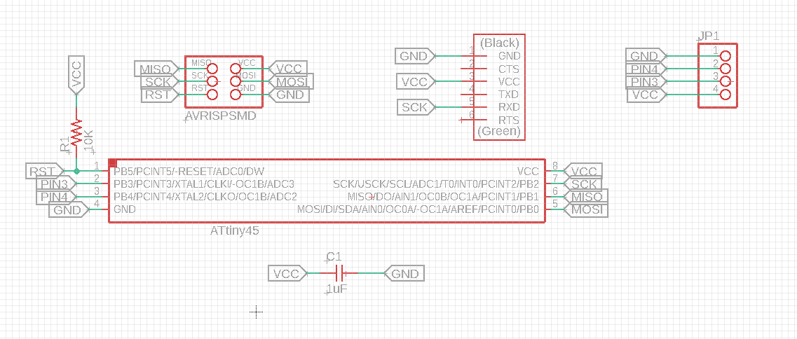
Click here to download the schematic.
Board
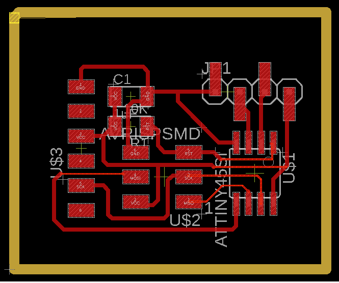
Click here to download the board.
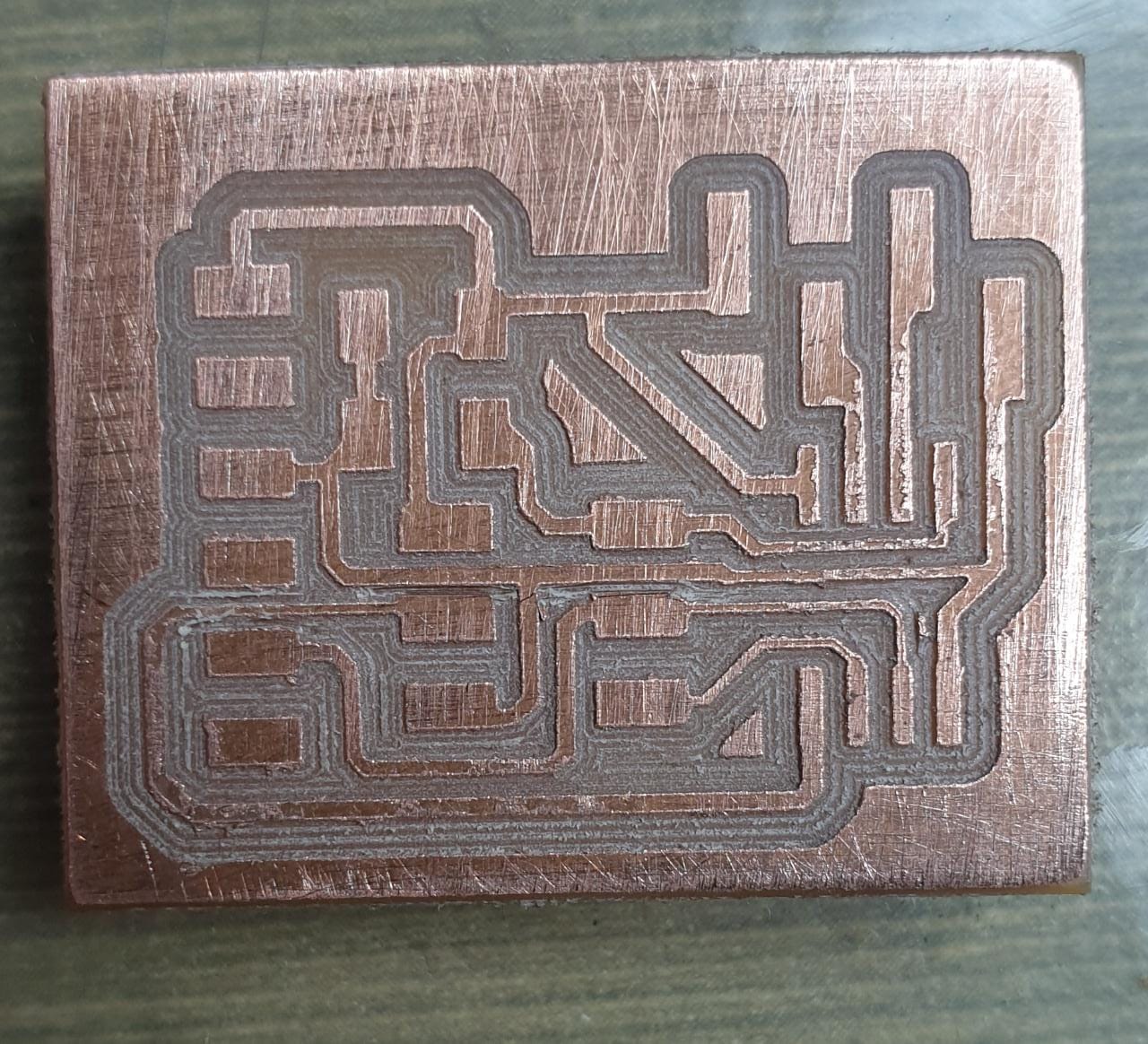
Milling
Soldering
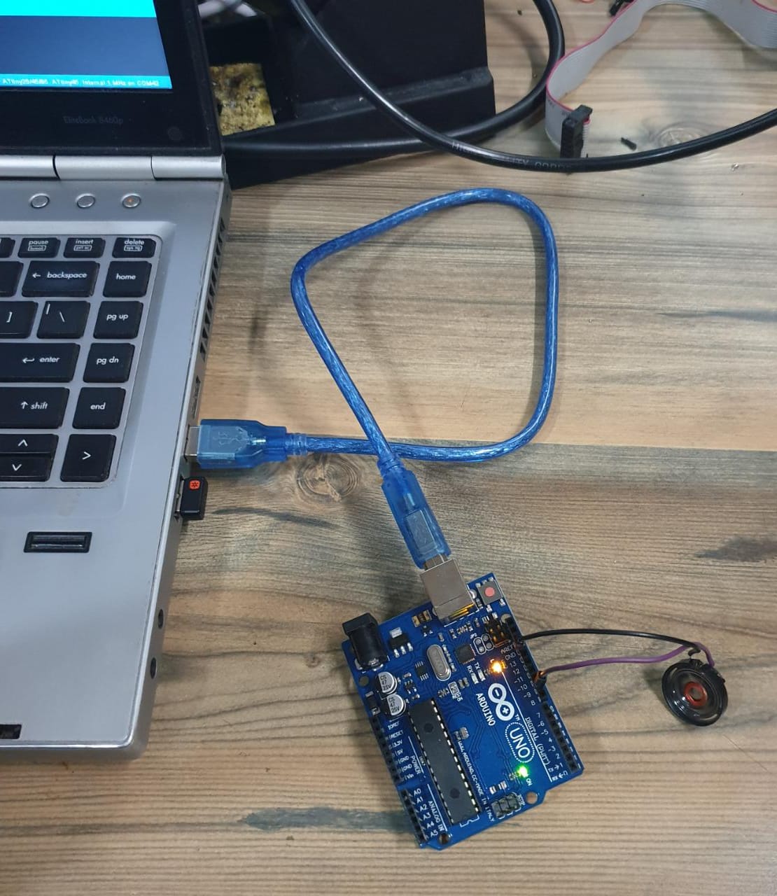
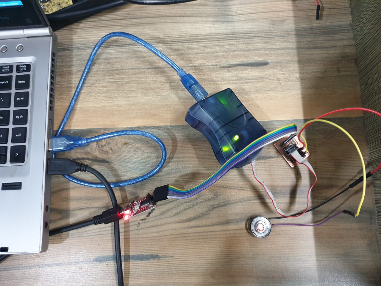
Connections
For programming I used avr programmer and gave 5v to the board from ftdi programmer. Connect one pin of the speaker to the pin 3 and other to ground.
Program
int speakerPin = 3;

int length = 15; // the number of notes
char notes[] = "ccggaagffeeddc "; // a space represents a rest
int beats[] = { 1, 1, 1, 1, 1, 1, 2, 1, 1, 1, 1, 1, 1, 2, 4 };
int tempo = 300;

void playTone(int tone, int duration) {
for (long i = 0; i < duration * 1000L; i += tone * 2) {
digitalWrite(speakerPin, HIGH);
delayMicroseconds(tone);
digitalWrite(speakerPin, LOW);
delayMicroseconds(tone);
}
}

void playNote(char note, int duration) {
char names[] = { 'c', 'd', 'e', 'f', 'g', 'a', 'b', 'C' };
int tones[] = { 1915, 1700, 1519, 1432, 1275, 1136, 1014, 956 };

// play the tone corresponding to the note name
for (int i = 0; i < 8; i++) {
if (names[i] == note) {
playTone(tones[i], duration);
}
}
}

void setup() {
pinMode(speakerPin, OUTPUT);
}

void loop() {
for (int i = 0; i < length; i++) {
if (notes[i] == ' ') {
delay(beats[i] * tempo); // rest
} else {
playNote(notes[i], beats[i] * tempo);
}

// pause between notes
delay(tempo / 2);
}
}
Working video
Learning Outcomes
- This week I learned to program the stepper motor.
- I never tested or played a tone in speaker using arduino or microcontroller. I learned to program it and was able to program it successfully.

This work is licensed under a Creative Commons Attribution-NonCommercial-ShareAlike 4.0 International License.