15. Mechanical design
This week basically was a group project to do following things
-
For the Group assignment: 1. Design a machine (mechanism + actuation + automation) 2. Build the mechanical parts and operate it manually. 3. Document the group project
-
For the Individual assignment we had to document our individual contribution.
Getting Started
You can find all details about the machine on our group page
Deciding the machine
- We spent quite a lot of time on discussing and debating about what we should build, what activities will be required and who will be doing what. Some of the group members wanted to build a machine that could make another machine and others wanted to build an injection molding machine. I felt that this was too ambitious given that none of us in the group had built a machine before. I wanted the group to build something simpler to start with where we could get help from the instructors if we stumbled along the way, the parts for which were readily available so that we could finish within time and we had the necessary skills to finish the machine building in time. What we agreed on as a group was to build a modular machine which had a common motion control system for x, y and z directions. There should be scope to change the end-effector to achieve different functions such as adding an extruder system to make a 3d printer, adding a spindle for cnc engraver, a laser for laser cutting, a pen for a plotter, adding a microscope for a tele-medicine system, etc. So we decided to do rapid prototyping first and explore all options like few members of the group would work on building Hector, which is an open access medium sized CNC machine started by Jens as his fab academy project. Few team members wanted to build a motion control system for x, y and z and make an xy plotter machine. I personally was intrigued by the idea of cardboard CNC as part of Machine that make machine and wanted to pursue that. This seemed achievable as it was just cardboard. If we are successful, others could learn from the mechanisms and electronics and they could also add further functionalities.
Deciding the Mechanical Design
-
As there was no consensus on working on just one machine we decided to try all options but with common electronics section. Only thing that was changing was mechanical design of machine.
-
We decided to work on three different type of mechanical mechanisms HECTOR for rack and pinion.
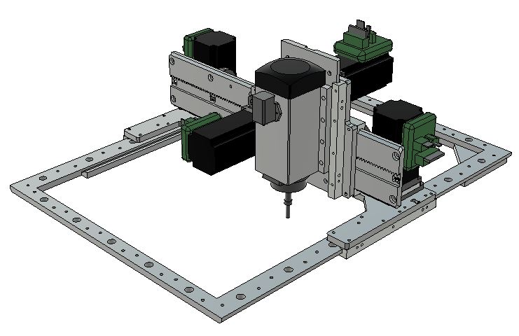
- Machine that make machine cardboatd CNC by Nadya Peek using Lead Screw Mechanism
- XY Plotter using Lead Screw and timimg Belt Mechanism
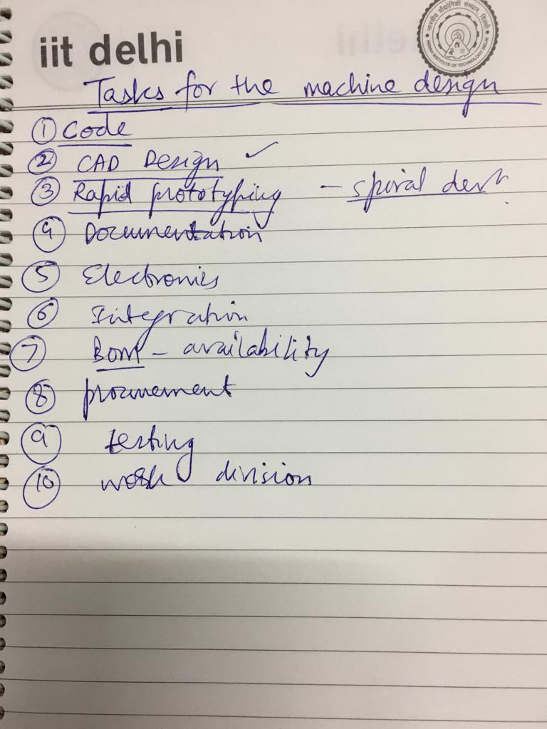
Deciding the tasks
As a team we decided like what we need for this group project and segregated each task within the group. First we agreed that we need to do Rapid prototyping to understand it better what actually is needed.
Number 1 priority for the task we agreed amoung ourselves was to do Rapid prototyping and try out following options before we decide the segregation of work.
- Try hector mechanism after cutting its design files on CNC/Laser
- Try out nadya peek cardboard based design on laser
- Outsource the milling of aluminum parts for hector as in fab lab we dont have metal CNC available
Division of Roles
This was a crucial step to ensure that the machine is made within time and operational. So we decided to divide the roles as per everybody’s comfort and experience.
So here’s how we divided the roles :
-
Rajat Ratewal(that’s me): Overall group project co-ordination, Electronics, Documentation for MTM, Mechanical design MTM machine
-
Narender Sharma: Mechanical Design for MTM machine
-
Jai Dhariwal: XY Plotter design and assembly, Documentation for XY Plotter, firmware and electronics
-
Shakti Sharma: XY Plotter design and assembly
-
Ali Ahmad: Hector design and assembly, Documentation for Hector
-
Ashish Sawhney: Hector design and assembly, Co-ordination with vendors on metal CNC
After the division of roles our group started working on the mechanical design first. For the raw materials we used what was available in the lab . We used some older projects which we dismanteled (ohh.... we are heartless people ) and then used them to make the sturcture of the machine. Apart from that we outsourced metal cutting for Hector and used 3d printing to build custom part.
MTM Mechanical Design
Mechanisms
- First thing me and Narendra stared was to understand Lead screw mechanism.
- We then started with the respective design available at Nadya page
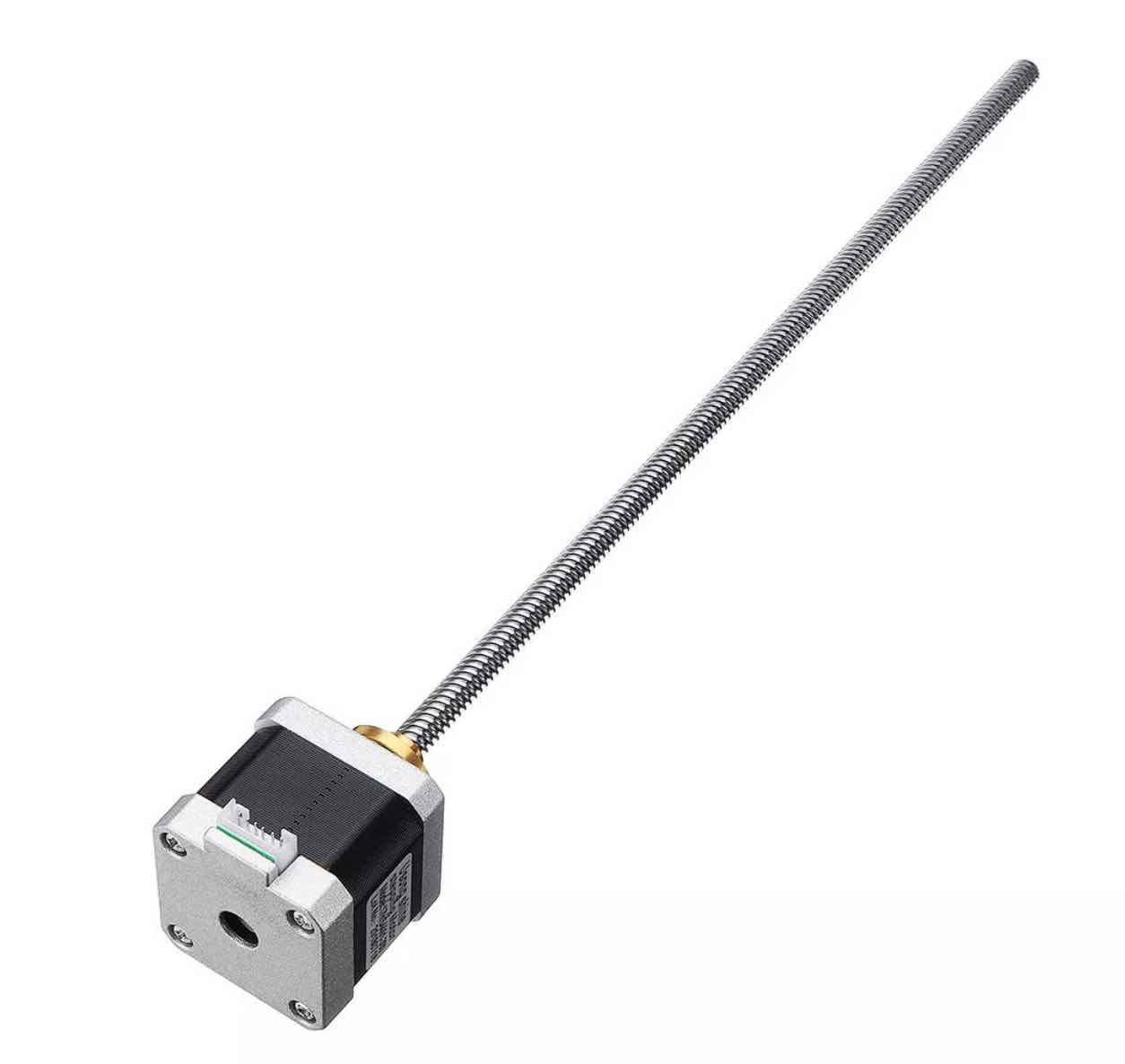
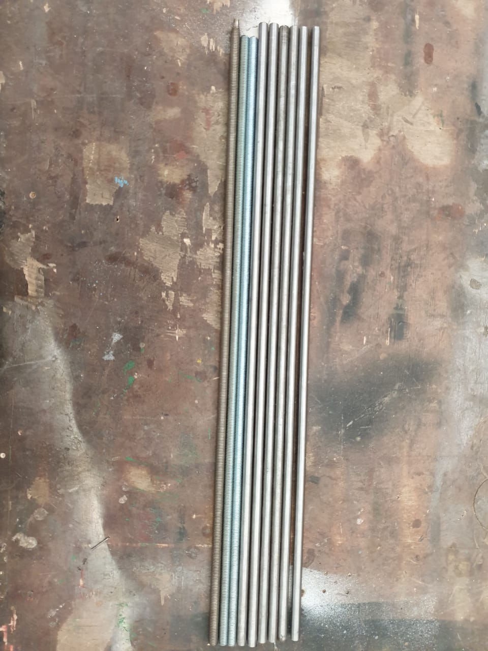
- We needed guide Rod , Threaded rod attached to stepper motor for the mechanism to work. So basically to get a mechanical motion we just need to attach stepper motor to threaded rod.
Actuation
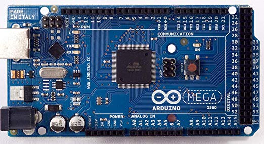
The actuation was achieved with the help of nema 17 stepper motors. The stepper motors used A4988 motor drivers for getting the right current. The signal pins of motor drivers were connected to an Arduino Uno.
Automation
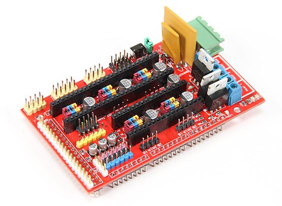
Also this weeks assignment was to automate the movement of motor and achieve desired positioning through mechanical system i.e we have to make it work. So my role in this weeks assignment was to work on the firmware and electronics of the system. So I started with understanding the working of stepper motors then I moved ahead towards its drivers. And then I learnt about interfacing it with arduino. Finally we decided automation using CNC shield placed on an Arduino Uno. The stepper motors and the corresponding motor drivers, servo motor and power supply were connected to the CNC shield. GRBL 0.9 firmware was uploaded on Arduino Uno. Inkscape version 0.47 vector 2D software was used to create the sketch. An extension was used in Inkscape to convert the sketch to tool path in g code format. This g code was sent to the microcontroller using universal g code sender software for automation.
Gaps we found in making of MTM design
- First thing was the design files on Nadya page were missing for that i raised a gitlab issue and hurrah we got some response these are the new links which were shared by Nadya MTM Machine new link, link to the cutfile, rhino model,grasshopper file
- We don’t had the right stepper motor (with lead screw rod attached) in lab and also the lead time to get it was also not sufficient to get this part. This was something that we needed to fix for machine to work.
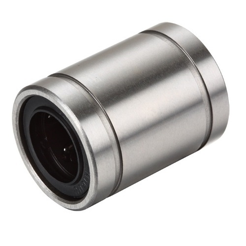
- We were missing linear bearings used in the design
Fixing the Gaps
We were hell bent on making MTM so we decided to improvise the design. Key aspect was to test the mechanism in this week for MTM. Though our state was like this below we decided to look for alternatives.

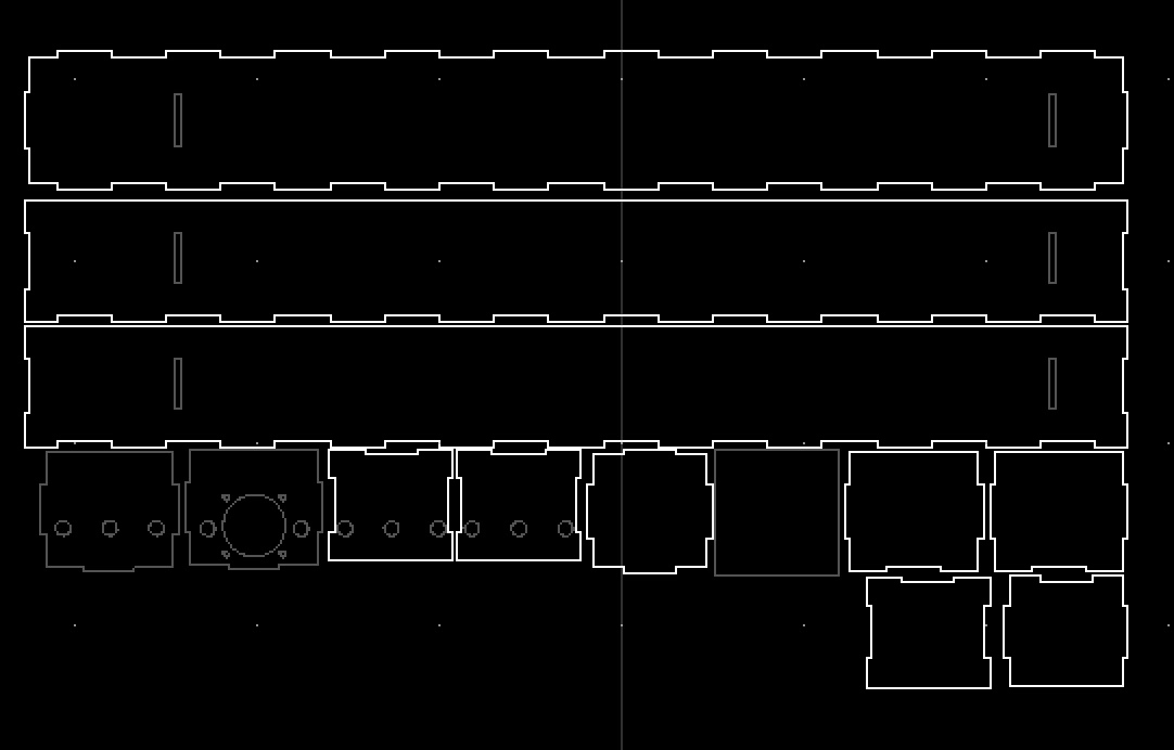
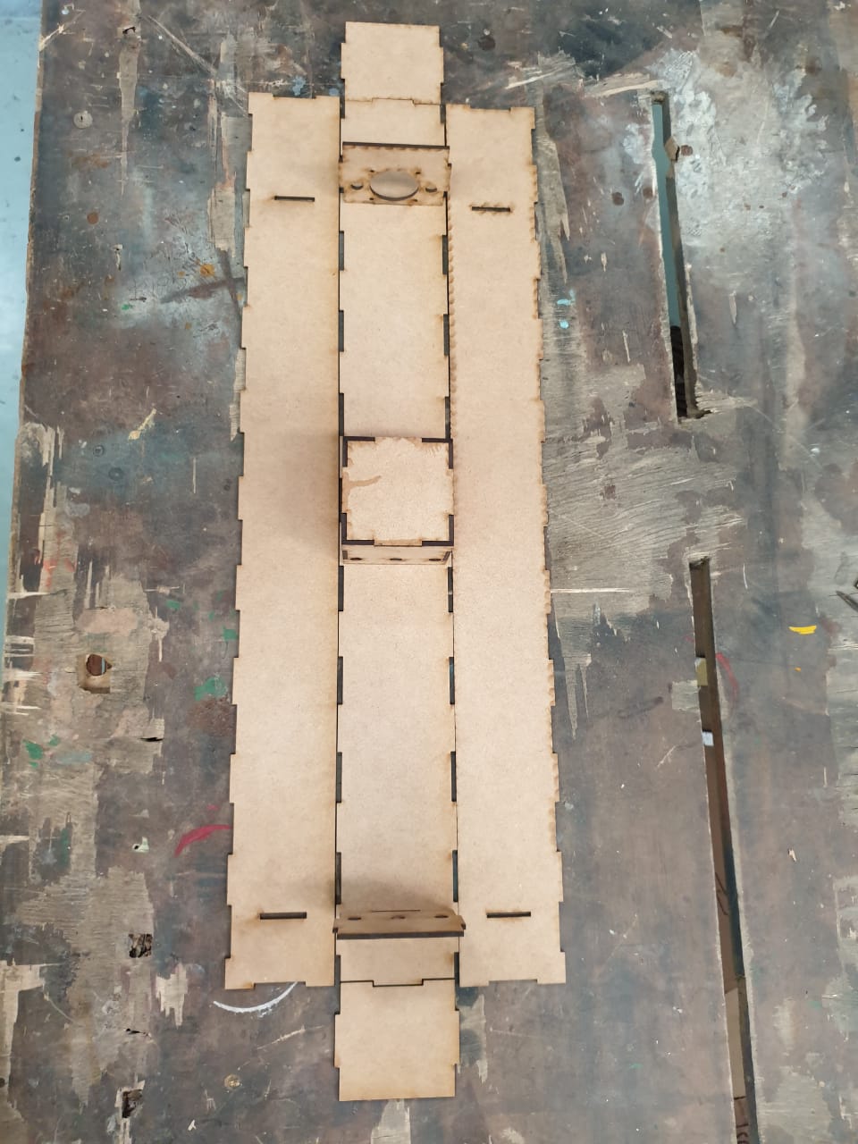
Design the Cut Files
As we were unable to get response in time we decided to go ahead and design the files from scratch for design. It was simple enough so we faced no issues. Please refer group page for more details.
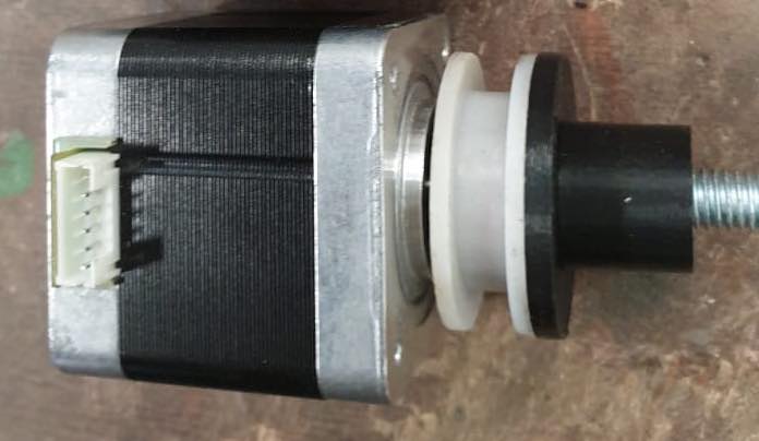
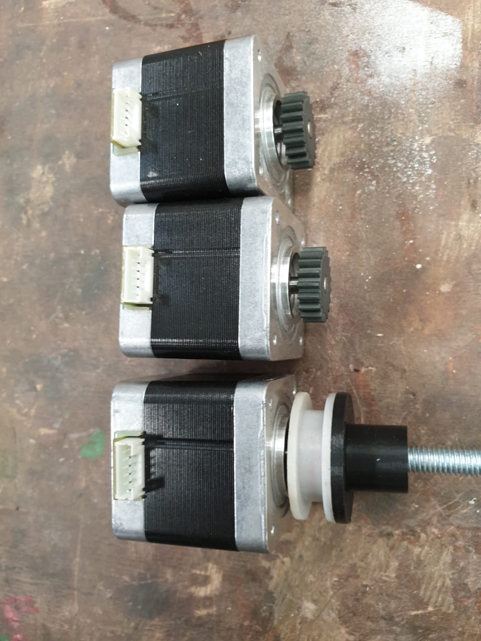
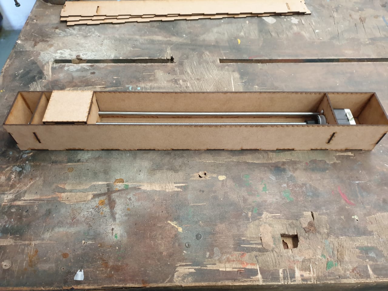
Create our own version of Threaded Rod coupling with stepper motor
Please refer group page for more details and files on how this was designed group page. This is what we had to improvise as we were unable to get coupler and right stepper motor.
BOM for the MTM machine
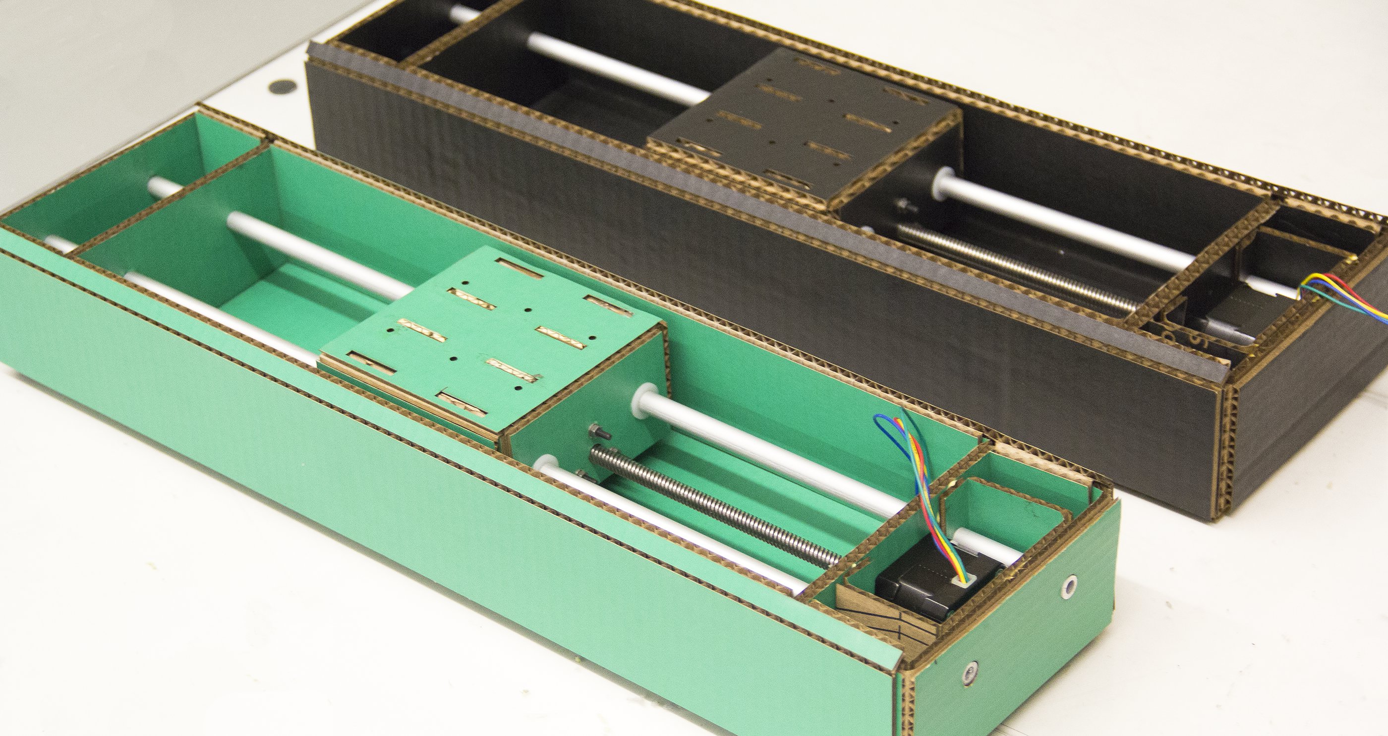
Guide Rods and Threaded Rods
Stepper Motors
CardBoard

RAMPS
Arduino
Screw and Nuts

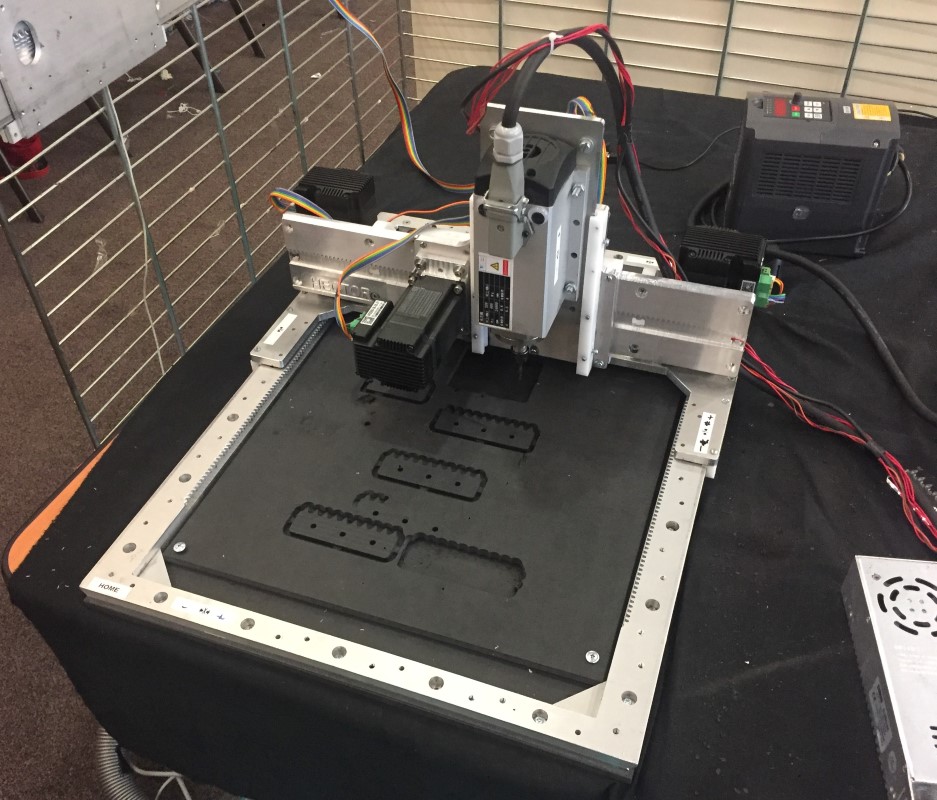
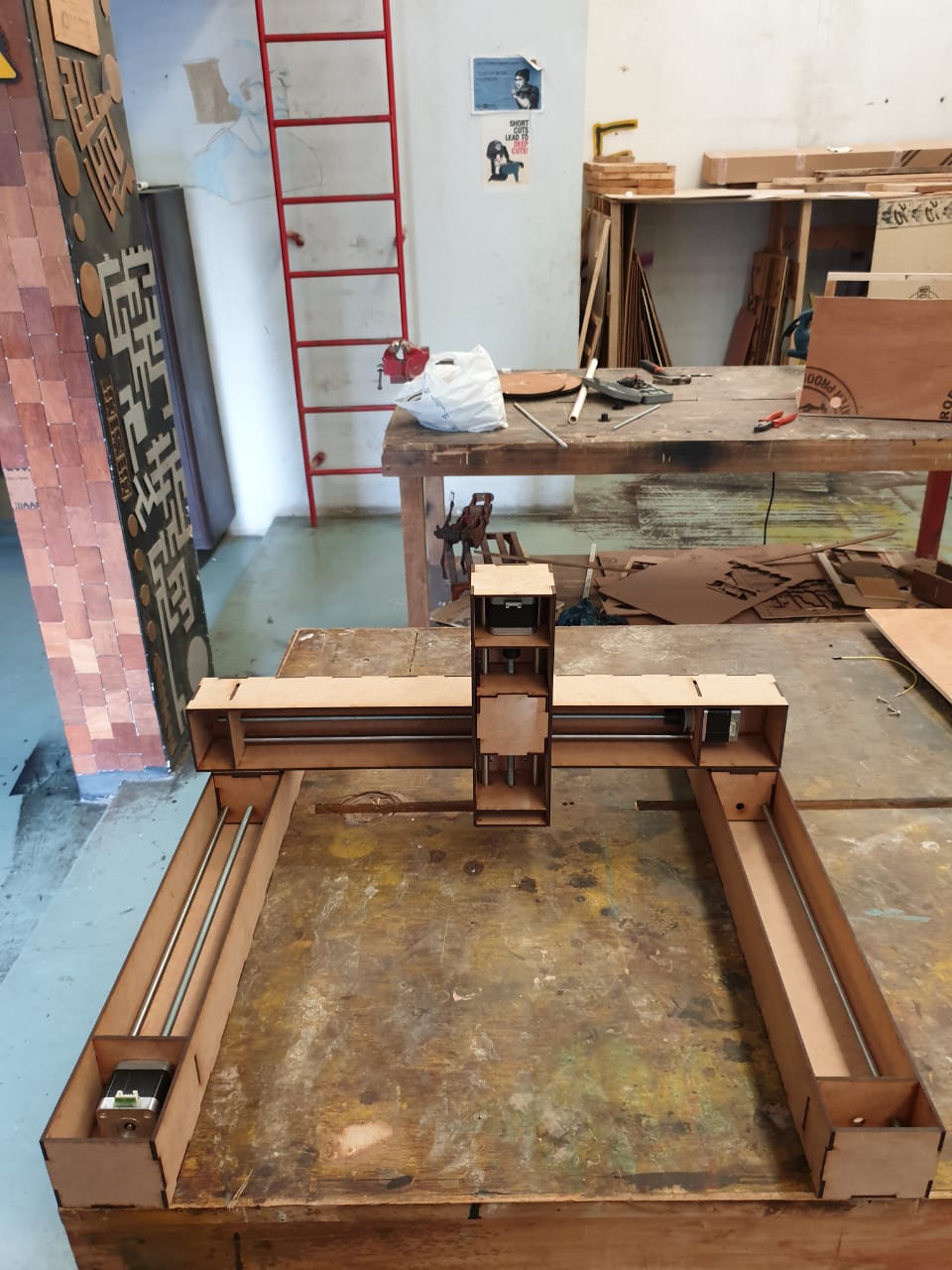
Final assembly of X,Y,Z Axis
Once we had these parts available and design gaps fixed we were able to achieve below outcome.
Machine Operation
The test result were not that perfect but the key thing was that we were able to understand the Lead screw mechanism in detail.
Here is the hero video for Lead screw mechanism working.
Overall Learning
- Personally this week was all new to me as i had never build a machine
- I was able to understand the Lead screw mechanism and how this is used in various machine. Like in Makerbot replicator this is getting used to caliberate the machine and move the platform up and down. So its a widely used mechanism
- Learnt about how to improvise in case of missing parts
- Bringing everyone on same page and agreeing on way forward was tough but we were able to work on a plan
- Looking forward for machine design week and see what we build up, i am excited for next week. Please refer this link to go to check details on final machine working.