9. Embedded programming
Group assignment:
For the group assignment we had to try different controllers.
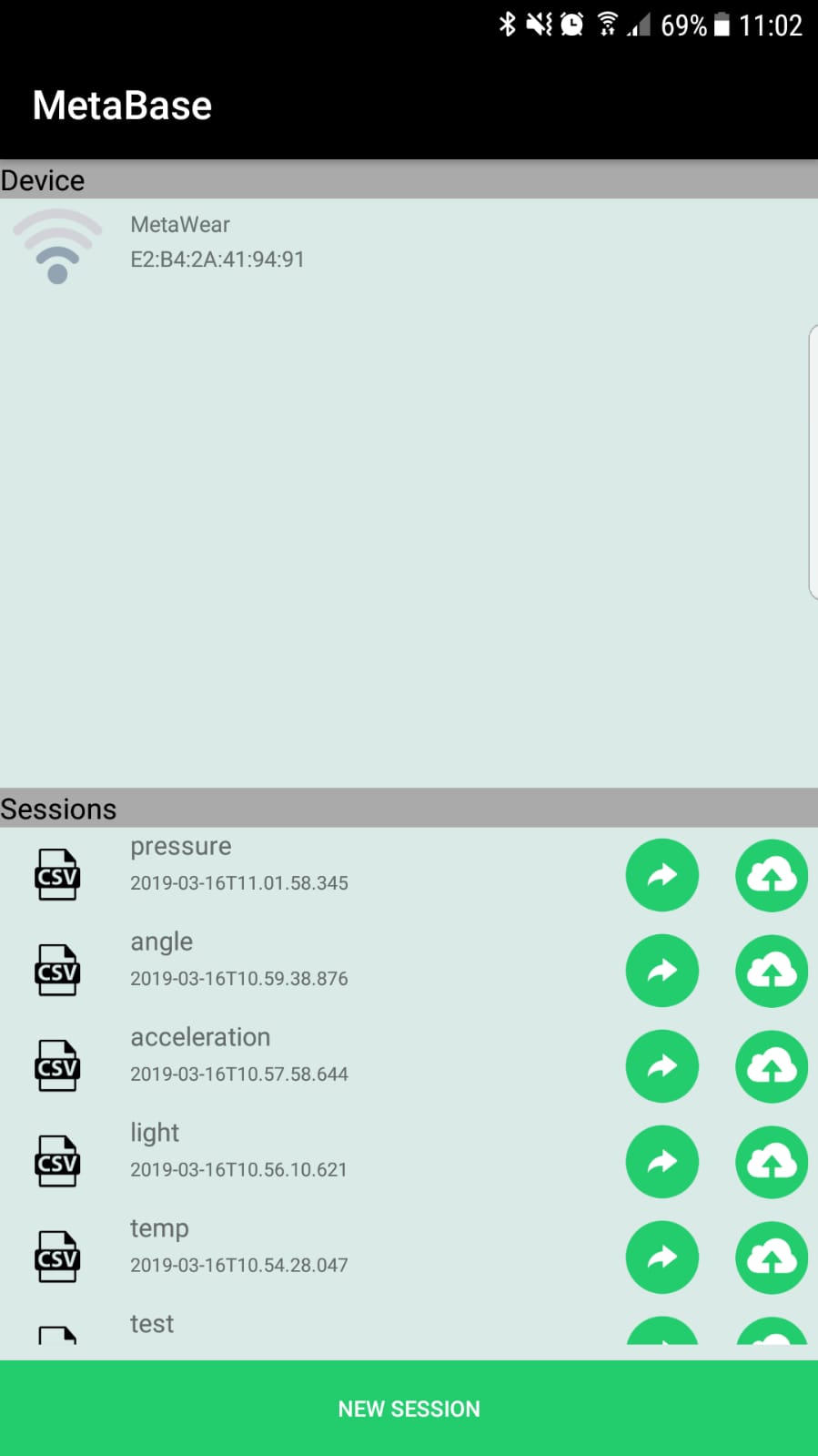
I started with the “MetaMotionR” its a chip the has alot of sensors such as pressure, temprature and accelerometer. It is connected to the phone through buletooth and controlled by an app.
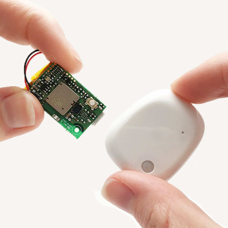
This is how you Setup your board.
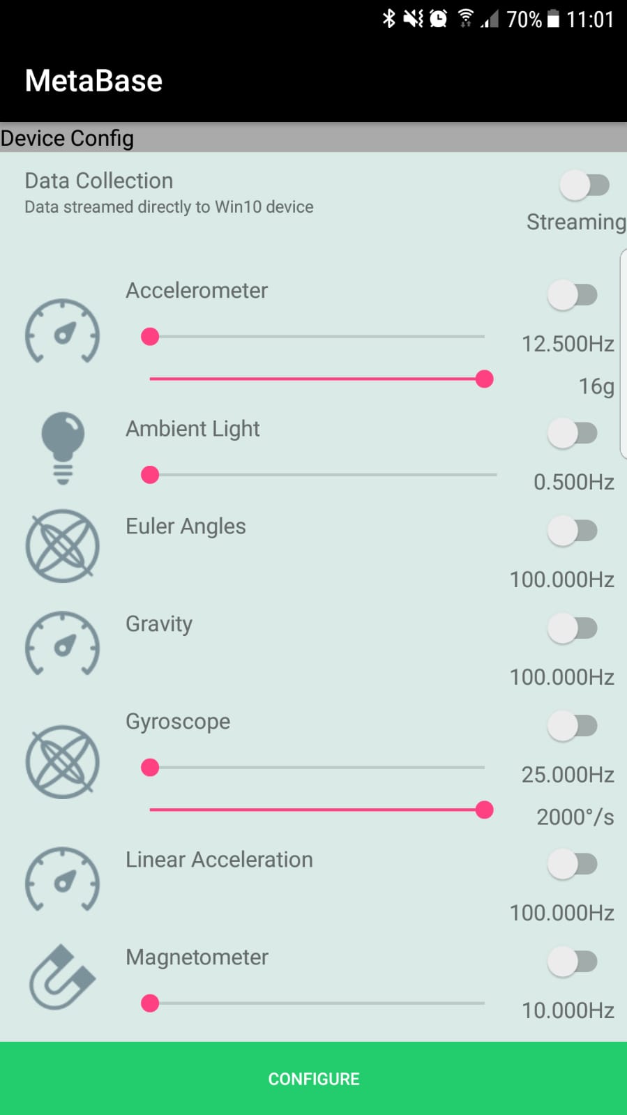
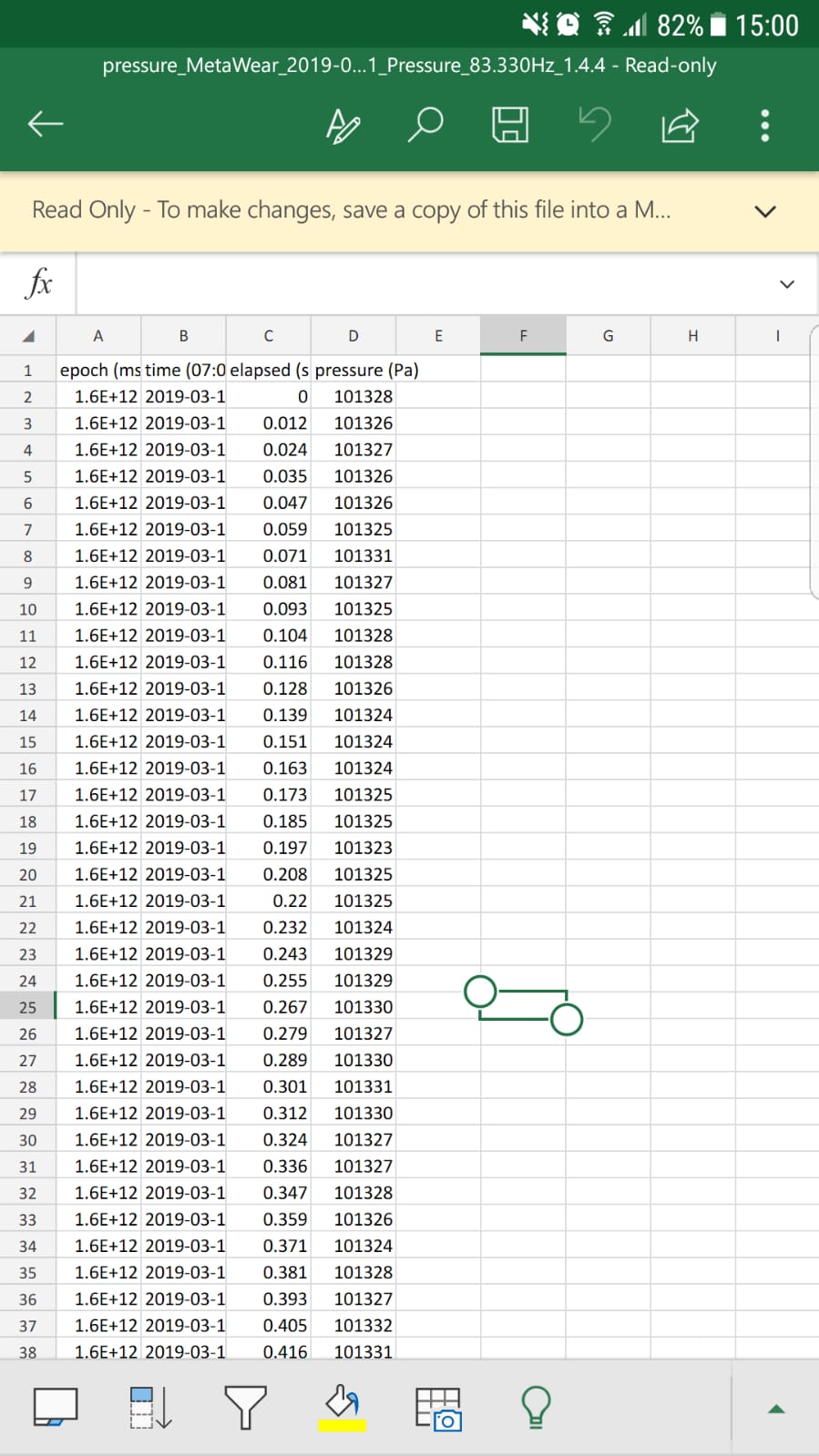
You can choose in the app the parameter you need then the chip will send you the data as Excel sheet.
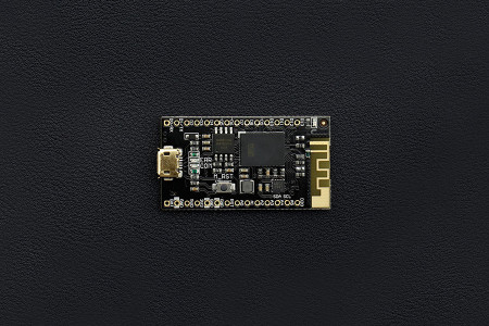
Then I worked on “curienano board” which is a smaller version of the arduino 101.
Following these tutorials 1 and 2 that showed how we can use the arduino ide with scrach for arduino “S4A” to control the board LED using the labtop arrow keys.

Week assignment:
In this week we will program our PCB board which we made previously using defferent programming languages such as BASIC, C, C++ and Java.
Datasheet
Going through the datasheet I discovered that our microcontrolles has different parts inside .For example the working register is responsible for the operations (+-*/) and its like a boxes that when you put different binary numbers inside it will response defferently . I would also like to learn the defferences between varios microcontrollers preformance and how to use all the available pins.
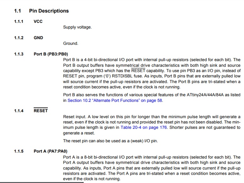
This picture shows that the atttiny microcontroller have pins and each pin is used for defferent applications.
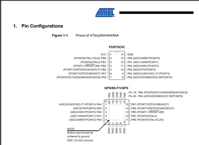
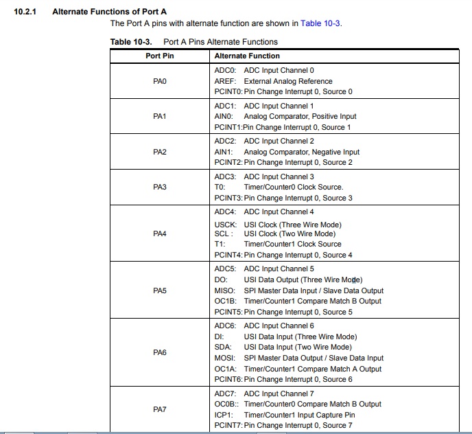
Here are the use of each pin vcc is the positive input power and the gnd is the negative input power. For port A it consist of pins A from 0 to 7 ADC means analouge to digital converter that means we can connect input or output devices an example for input the signal of a button or sensor. The analog to digital converter is important because the sensors output signals are always analouge due to measuring the changable phisical quantity In addition the microcontroller understands only digital data. Moreover the reset pin is used to switch on or off the microcontroller.
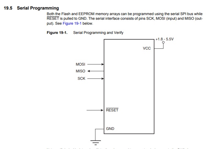
This figure shows the range of power input for the microcontroller and the pins needed for programing.
Steps
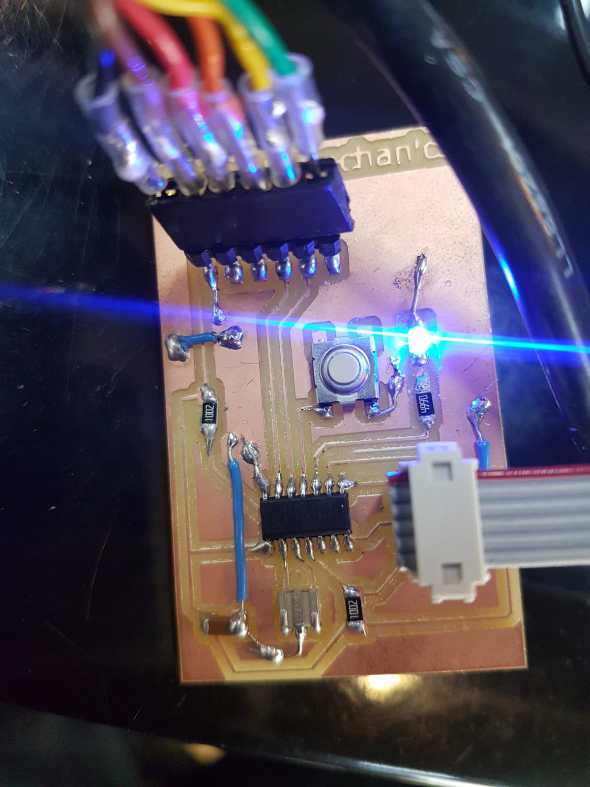
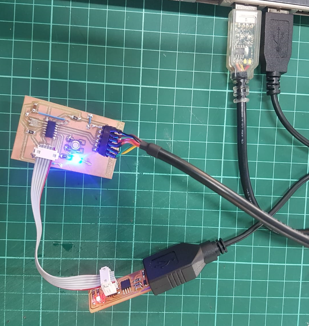
First we should connect our microcontroller “our second PCB” to a programmer “our first PCB” “tiny ISP” so we will be able to transfere the code to our microcontroller.
Arduino IDE:
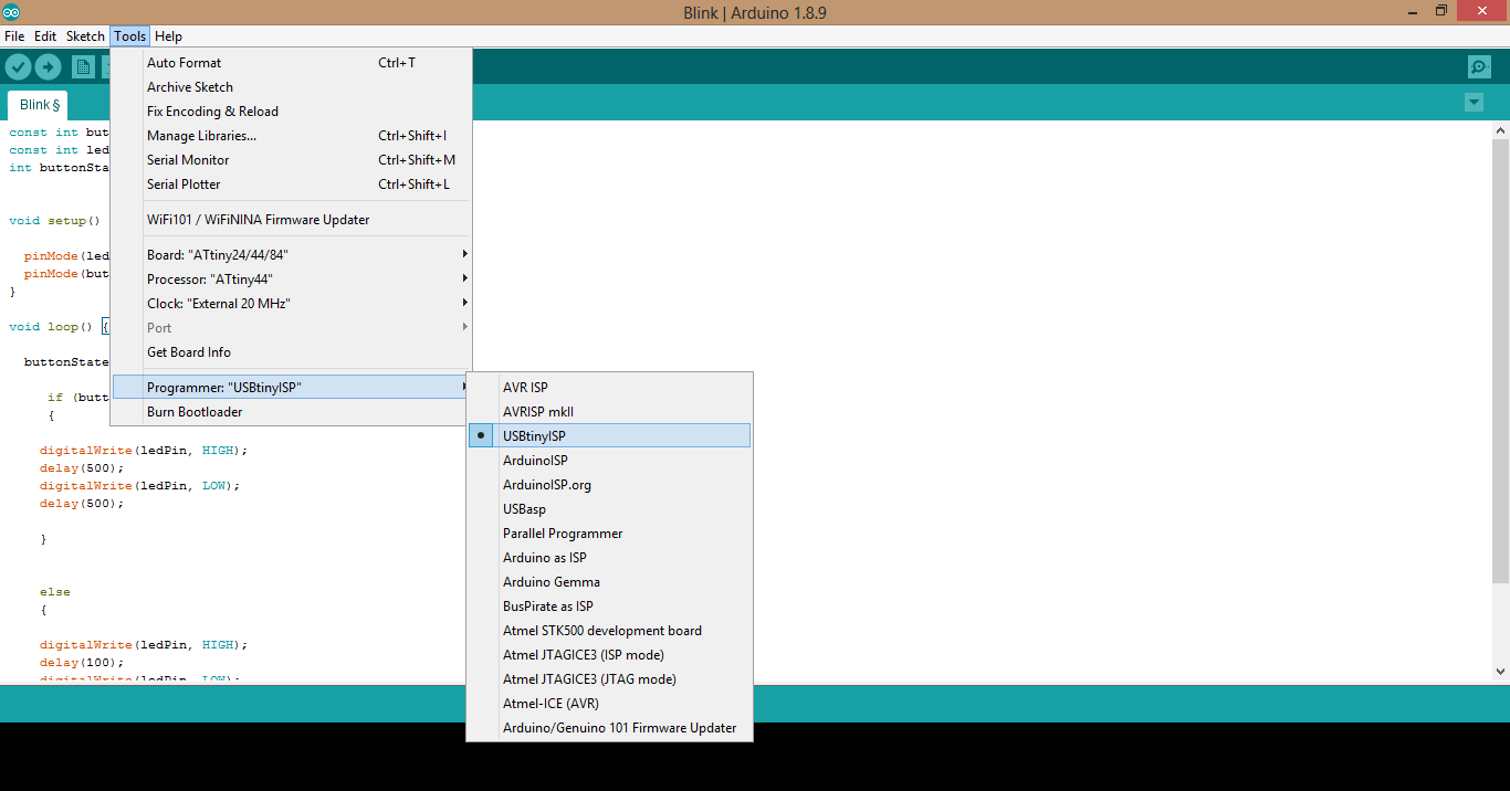
I will program my microcontroller using our board “tiny ISP” so the settings has to change.
const int buttonPin = PA2;
const int ledPin =  PA3;
int buttonState = 0;


void setup() {

  pinMode(ledPin, OUTPUT);
  pinMode(buttonPin, INPUT);
}

void loop() {

  buttonState = digitalRead(buttonPin);

     if (buttonState == LOW)
     {

    digitalWrite(ledPin, HIGH);
    delay(500);
    digitalWrite(ledPin, LOW);
    delay(500);

    }


    else
    {

    digitalWrite(ledPin, HIGH);
    delay(100);
    digitalWrite(ledPin, LOW);
    delay(100);

    }

}
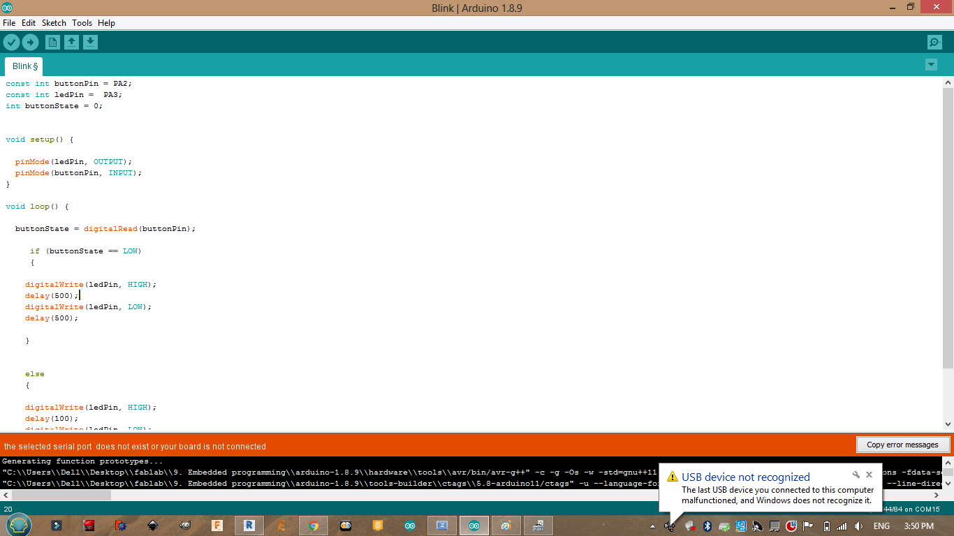
Using this code I was able to make the LED blink at a sertain frequncy then when the button is pressed the frequency will change.

Problems:
When we connected them the labtop showed that the “tiny ISP” was unrecognized by the system so we had to solve this issue.
It was a driver issue:
Then there was an error in the adrduino ide for some reason.
Atmel studio
I recommend this site
Steps
1-Download Atmel Studio.
2-Connect the AVRISP with your board and the computer.
3-When you open Atmel Studio click >> New Project >> GCC C Executable Project >> OK.
4-Device Selection >> ATtiny44 >> OK.
5-Create your program :
#define F_CPU 20000000    // AVR clock frequency in Hz, used by util/delay.h
#include <avr/io.h>
#include <util/delay.h>

int main() {

    DDRA |= (1<<PA7);          // set LED pin to output
    while (1) {
        PORTA |= (1<<PA7);   // LED high
        _delay_ms(500);         // delay 500 ms
        PORTA &= ~(1<<PA7);  // LED low
        _delay_ms(1000);         // delay 1 s
    }
}
6-Toolbar >> build solution.
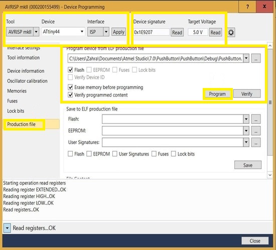
7-Tools >> device programming :