7. Electronics design
This week I worked on defining my final project idea and started to getting used to the documentation process.
Group Assignment
You can find our group assignment in this link.
Eagle
I have downloaded Eagle from their website . I went through the documentation in this link & tried to implement the steps in this tutorial. I looked at some other students previous work like Solomon, Derek & Duaa.
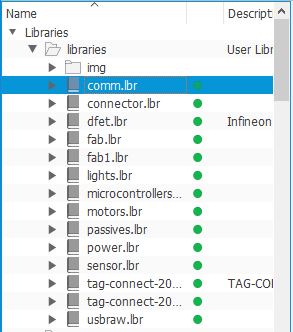
I have created a new project, then new schematic. Then, I added Fab library & some other libraries in Eagle by clicking on Library > open library manager > In use > Browse > chose the library > open. Then, I enabled them.
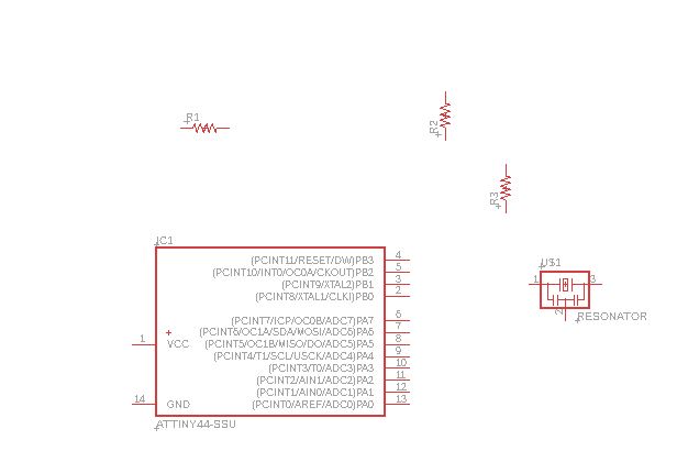
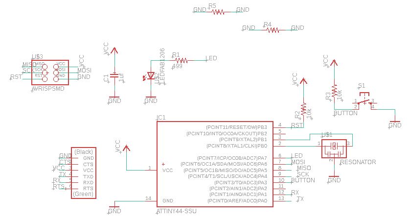
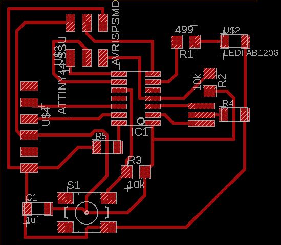
I started adding some components & then connecting the parts by clicking on the “Add part” icon from the tool bar. Then, a list of all the available libraries will be displayed. After that, I chose the library that contained the components and clicked on the components that I wanted to add to my schematic. I got some of the components from Fab library.
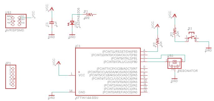
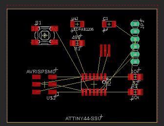
Then I switched to the board & had to arrange the circuit components.
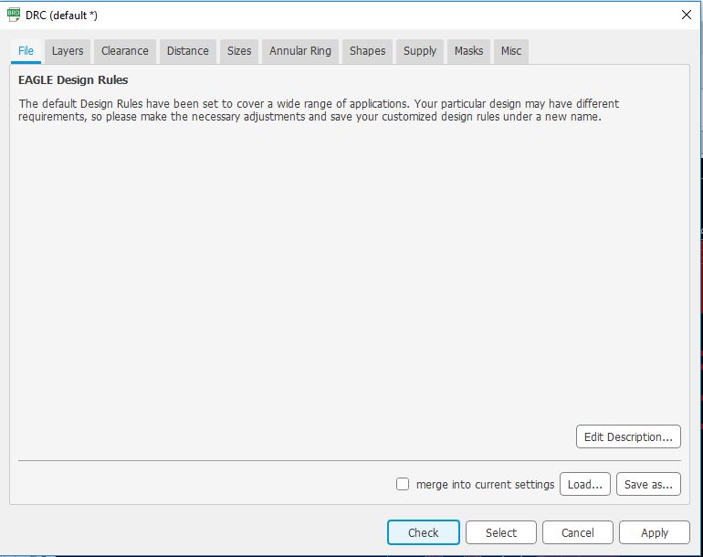
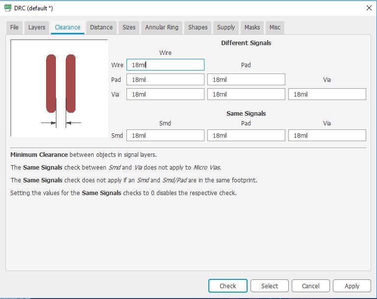
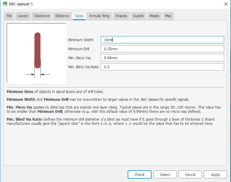
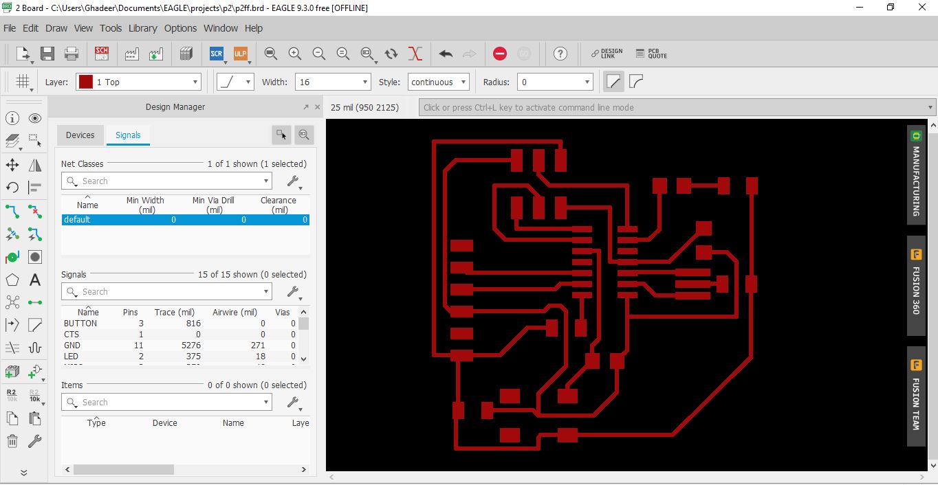
I had to change desing rules to ensure that our design is within the limit.
click Tool >> DRC The width should be 16
It took me a long time to find the best routing for the circuit (without needing to use another layey) but because I didn’t add the design rules at first, I had to rechange the circuit & find a better way. At the end I had to add 2 0 ohm resistors.
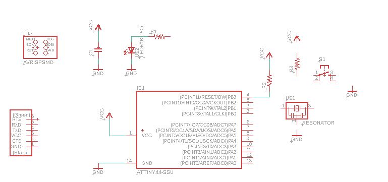
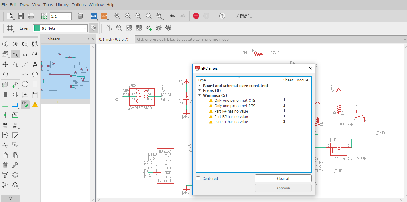
I did ERC check for the schematic, it showed some warnings that will not cause any issues like not setting a value in the schematic for the 0 ohm resistors & that there only one pin on two nets because they are not connected to anything.
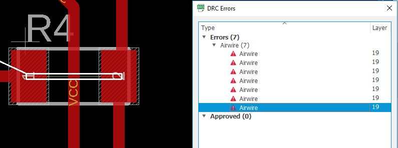
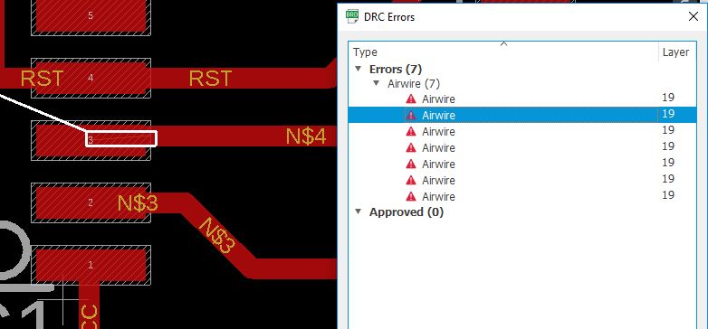
Then did another DRC check it showed one wire stub which I removed.
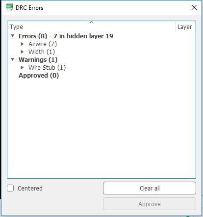
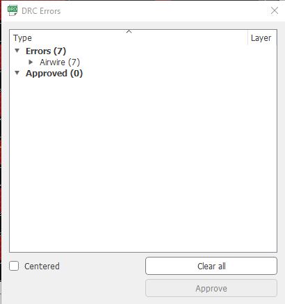
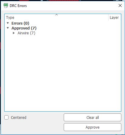
& it showed some air wire where I putted the 0 ohm resistors & some other parts that are connected, so I approved these errors.
This is the final routing for the circuit & exported the top layer as an image.
Eagle Board (right click + Save link as)
Eagle Schematic (right click + Save link as)
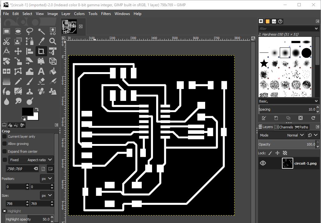
Then, I opened the image in GIMP & created the traces & border images.

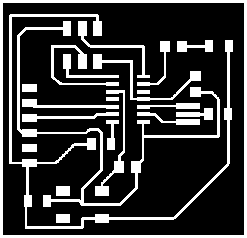
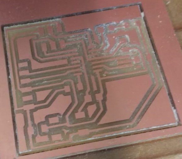
This is my milled PCB. Milling steps were simillar to these steps.
Border rml file (right click + Save link as)
traces rml file (right click + Save link as)
I have used this LED in my circuit. The LED needs 20 mA and has a voltage drop of 2 volts. Since there is a 2 volt drop over the LED, there will be a 3V drop over the resistor. So, we will have 3V and we want to have 20 mA going through the resistor and the LED. To find the necessary resistor value we use Ohm’s law.
V = R * I
R=V/I= 3/0.02= 150 ohm
But I used 499 ohm resistor since a bit higher resistor value will not cause a negative effect on the circuit.
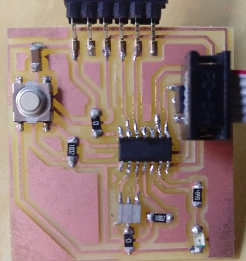
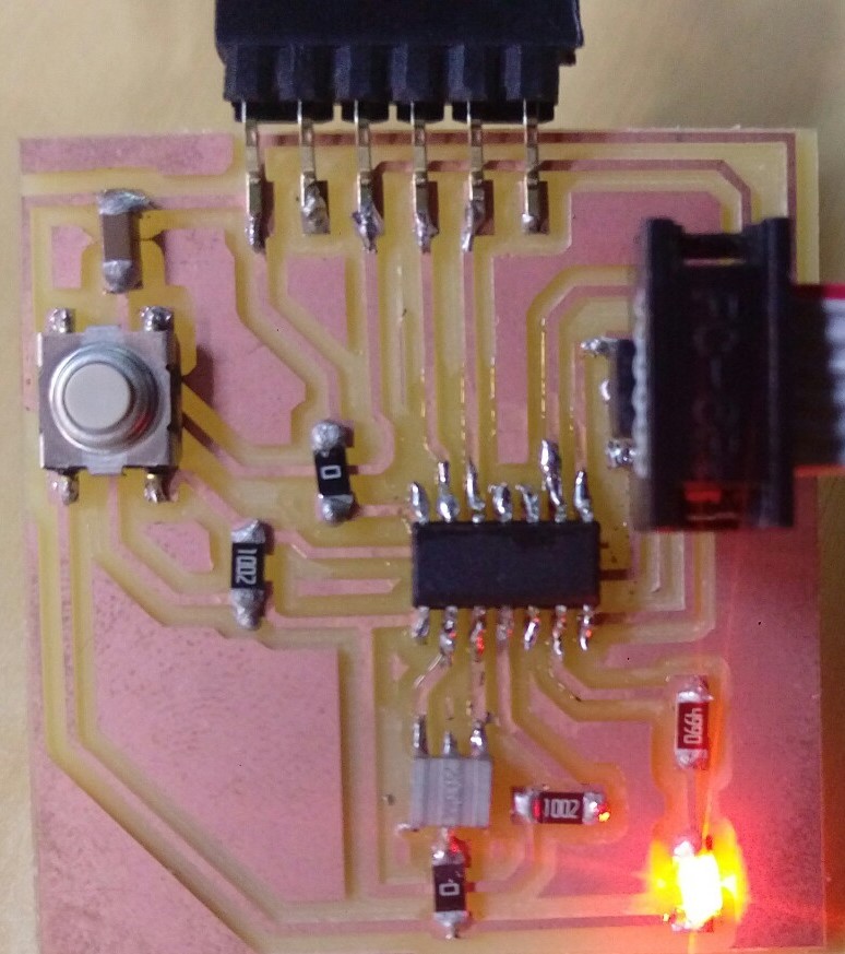
After soldering the parts I tried to test the PCB. but it showed that there were some errors in the connections. It turned out that I soldered the ATTINY44 not in the right position. Therefore, it was desoldered using heat gun & braid, then resoldered it. Unfortunetly, I didn’t take photos of the steps. This is the final look of the PCB.
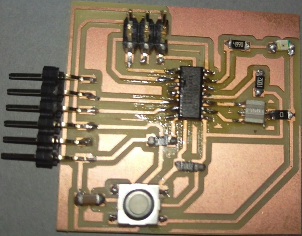
Then the connection testing was successful

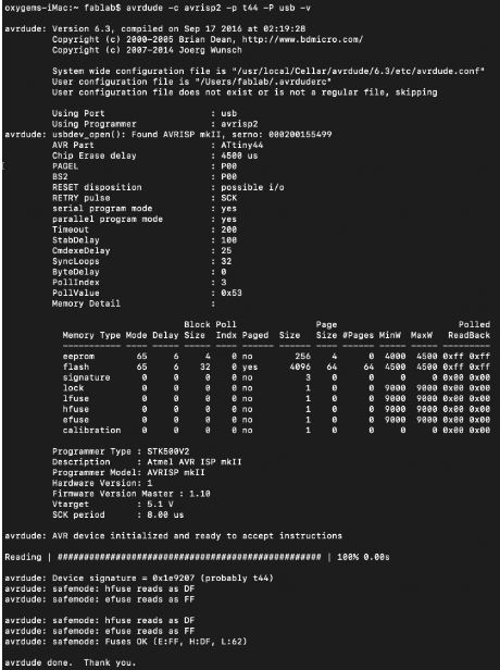
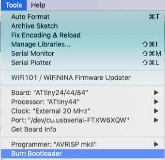
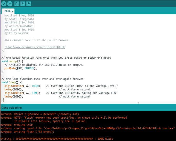
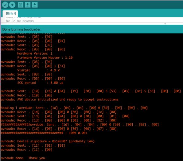
Then I tried todo some programming testing using Arduino Using these settings & coding. However, the LED took longer than 1 second to blink, so I had to select burn bootloader. After that, it worked properly.