12. Output devices
This week I worked on defining my final project idea and started to getting used to the documentation process.
Group Assignment
Servo Motors
Servo motors use feedback to determine the position of the shaft, you can control that position precisely. As a result, servo motors are used to control the position of objects, rotate objects, move legs, arms or hands of robots, move sensors etc. Servo motors are small in size, and because they have built-in circuitry to control their movement, they can be connected directly to my circuit. Information source link .
Most servo motors have the following three connections:
-
Black/Brown ground wire.
-
Red power wire (around 5V).
-
Yellow or White PWM wire.
Servo control is achieved by sending a servo a PWM (pulse-width modulation) signal, a series of repeating pulses of variable width where either the width of the pulse or the duty cycle of a pulse train determines the position to be achieved by the servo. The PWM signal might come from a radio control receiver to the servo or from common microcontrollers such as the Arduino.
The parameters for the pulses are the minimal pulse width, the maximal pulse width, and the repetition rate. Given the rotation constraints of the servo, neutral is defined to be the center of rotation.
- Ton is the time for the high pulse
- Toff is the time for the low pulse
- duty cycle is the percent of Ton to pulse width (Ton+Toff)
1ms Ton 99ms Toff would make the following: Ton = 1ms Toff = 99ms period = 100ms Frequency= 1/(1*10^-3) = 10Hz Duty cycle = (1⁄100) = 0.01 or 1%
Circuit
I used the board that I made in input week for this week. Sometimes I have connected the motor the header where I connected the accelorometer & other times to the ISP header. I have connected the signal pin to PA6.
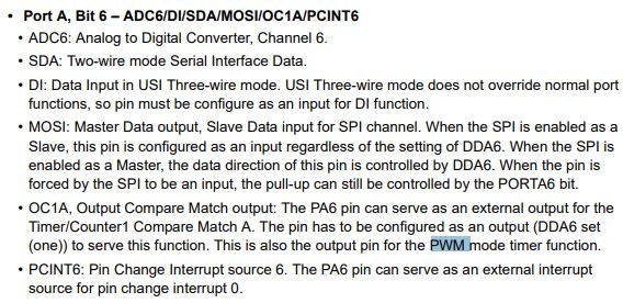
The ATtiny processors allow you to generate an analogue output using Pulse Width Modulation (PWM). One or more counters in the chip allow you to generate a constant-frequency square wave and specify the proportion of the time it’s off and on.
Arduino
This week I couldn’t program using Arduino from my laptop still not sure why, I get this message “avrdude: usbdev_open(): did not find any USB device “usb” “. I was able to program before but I recently got this message. The only changes I can think of are installing driver for USBtiny & installing some libraries. So, I did the programming using the lab computer.
At first, I tried to use the Sweep example code for servo motor in Arduino
/* Sweep
 by BARRAGAN <http://barraganstudio.com>
 This example code is in the public domain.

 modified 8 Nov 2013
 by Scott Fitzgerald
 http://www.arduino.cc/en/Tutorial/Sweep
*/

#include <Servo.h>

Servo myservo;  // create servo object to control a servo
// twelve servo objects can be created on most boards

int pos = 0;    // variable to store the servo position

void setup() {
  myservo.attach(9);  // attaches the servo on pin 9 to the servo object
}

void loop() {
  for (pos = 0; pos <= 180; pos += 1) { // goes from 0 degrees to 180 degrees
    // in steps of 1 degree
    myservo.write(pos);              // tell servo to go to position in variable 'pos'
    delay(15);                       // waits 15ms for the servo to reach the position
  }
  for (pos = 180; pos >= 0; pos -= 1) { // goes from 180 degrees to 0 degrees
    myservo.write(pos);              // tell servo to go to position in variable 'pos'
    delay(15);                       // waits 15ms for the servo to reach the position
  }
}
But it didn’t work. I tried different codes, some of them didn’t work because the library was not made to work for Attiny44. Then, we tried using a different library & it worked.
#include <Adafruit_SoftServo.h>

Adafruit_SoftServo servo;
int pos = 0;


void setup()
{

  servo.attach(PA6);

}

void loop() {
  for (pos = 0; pos <= 60; pos += 1) {
    servo.write(pos);
    delay(10);
    servo.refresh();
  }
  for (pos = 60; pos >= 0; pos -= 1) {
    servo.write(pos);
    delay(10);
  servo.refresh();
  }
}
However, the maximum movement was for about 90 degrees. We tried changing the code but nothing worked. Most probably we need to change some values in the library.
Pos=60
Pos=90

Pos=180
When I increased the value to above 180, the motor was not behaving normally.
Pos=350
C language
We tried to do the programming using C language to try & see if we can make it turn for around 180 degree. I used code directly from this my colleage website. Link to source
Source code
/*
 this code is used to demonstrate how to use servo motor and it just (blinks the servo)...
this code is written for Attiny44 and im using IO_board v1.0
code from
http://fab.academany.org/2018/labs/fablabbahrain/students/hasan-jaafar/project/w11_output/
*/
#define F_CPU 20000000UL
#include <avr/io.h>
#include <util/delay.h>

//Servo is connected to PA7 in IO_board v1.0
//led to PB2 in IO_board v1.0
#define seton(port,pin) port|= 1 << pin
#define setoff(port,pin) port&= !( 1<<pin )

volatile static uint8_t x = 1;

int main(void)
{
//port direction
    DDRA = 1<< PA7; //servo pin
    DDRB |= 1<<PB2; //led
    seton(PORTB,PB2);


   while(1)
   {

    for ( i= 0 ; i < 100; i++)
    { //1ms on -  19ms off
        seton(PORTA, PA7);
        _delay_us(1000);
        setoff(PORTA, PA7);
        _delay_us(1000);
        _delay_us(18000);
    }
    for ( i= 0 ; i < 100; i++)
    { // 2ms on - 18 ms off
        seton(PORTA, PA7);
        _delay_us(2000);
        setoff(PORTA, PA7);
        _delay_us(18000);
    }
   }
}
Slight changes were made
#define F_CPU 20000000UL
#include <avr/io.h>
#include <util/delay.h>
#define seton(port,pin) port|= 1 << pin
#define setoff(port,pin) port&= ~( 1<<pin )

volatile static uint8_t x = 1;

int main(void)
{
//port direction
    DDRA = 1<< PA6; //servo pin
    DDRA |= 1<<PA7; //led
    seton(PORTA,PA7);

   while(0)
{
seton(PORTA,PA7);
_delay_us(1000);
setoff(PORTA,PA7);
_delay_us(1000);
}
   int i=0;
   while(1)
   {

    for (i= 0 ; i < 100; i++)
    { //1ms on -  19ms off
        seton(PORTA, PA6);
        _delay_us(500);
        setoff(PORTA, PA6);
        _delay_us(1500);
        _delay_us(18000);
    }
    for (i= 0 ; i < 100; i++)
    { // 2ms on - 18 ms off
        seton(PORTA, PA6);
        _delay_us(2300);
        setoff(PORTA, PA6);
        _delay_us(17700);
    }
   }
}

Other
I have used output devices in other assignments like machine building & final project .