4. Computer controlled cutting
Objectives of this week are:
1- To work togather as a group to characterize our lasercutter + making test parts that vary cutting settings and dimensions.
2- To cut something on the vinylcutter.
3- To design and lasercut a parametric press-fit construction kit.
getting started with the laser cutter
I have started this week by learning how to use the laser-cutter. It is my first time using the laser cutter, so I have started by cutting the box that I have already created last week. As mentioned previously, I have designed my 2D model using openSCAD. So in order to cut the design with the laser cutter, I have followed these steps:
1- Save your openSCAD file and export it as DXF or SVG.
2- Open your file with the Inkspace software.
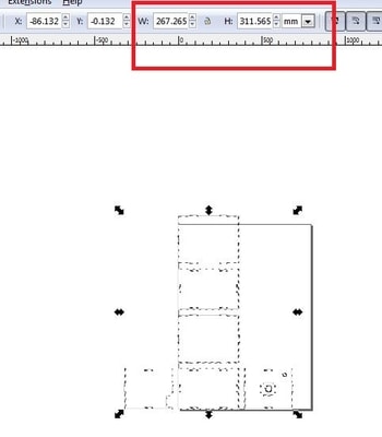
3- Check that the size of your design is correct.
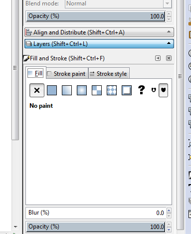
4- Go to the Fill and Stroke area by clicking on (Shift+Ctrl+F).
5- Set the fill to “no paint”.
6- Stroke paint to “255” to cut all through the material.
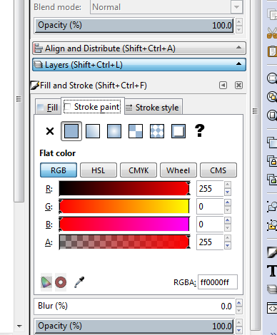
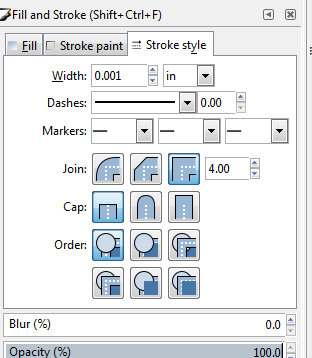
7- Set the stroke style to 0.001 inch because the laser cutter can detect thin line.
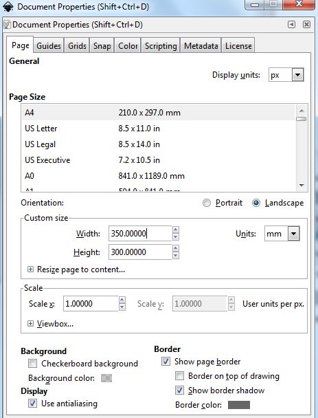
8- Check that your page size matches the laser cutter cutting area.
9- After you fit your design on the page size, save it as PDF file.
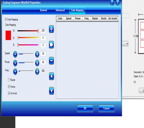
10- Open your PDF file and click on file > print > properties and you will see the following window. Based on the material that we want to cut, chose the laser speed, power and frequency.
- set the job type to vector ( so the laser cutter will follow the line )
- Check the box of the Auto Focus option so that the machine does not cut immediately and it do kind of calibration. .
- Make sure that the piece size is correct.
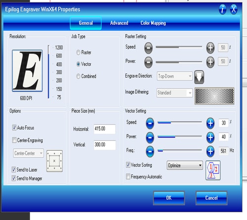
11- To set the your speed, power and frequency
- click on the Color Mapping
- set the parameters
- click on the “+” icon
- click OK
12- Finally, after you finish, in the epilog software, you will see that your file is added to the jobs and it will be appeared in the machine screen as well.
.jpg)
13- In your laser machine press the green button “Go” and it will start cutting.
Here is the final result
press-fit kit
For the press-fit construction kit I have worked on two designs, one with Rhino and the other with OpenSCAD. I have talked about openSCAD before in the previous week, so if you would like to know more about it, visit the last week page.
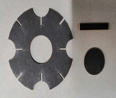
My press-fit design in openSCAD consists of two pieces, one of them has a circular shape and the other is rectangle. I have started by the first shape which is look like this:
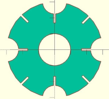
I have started this design by setting the values of the material thickness, cut depth and radius of the circle.
mth= 1.15; //material thickness.
d= 6; //cut depth, 6 mm.
circle_R= 30; //radius 30 mm.
then, I have draw the circle using this command
translate([0,0])
circle(circle_R);
After that, I have cut a small circle inside the circle that I have just drawn
difference (){
translate([0,0])
circle(circle_R);
translate([0,0])
circle(circle_R/3);
}
Then, I have cut 4 circles on the edges
difference (){
translate([0,0])
circle(circle_R);
translate([0,0])
circle(circle_R/3);
translate([circle_R,0])
circle(circle_R/4);
translate([-circle_R,0])
circle(circle_R/4);
translate([0,-circle_R])
circle(circle_R/4);
translate([0,circle_R])
circle(circle_R/4);
}
Then, I have made 4 rectangle cuts
difference (){
translate([0,0])
circle(circle_R);
translate([0,0])
circle(circle_R/3);
translate([circle_R,0])
circle(circle_R/4);
translate([-circle_R,0])
circle(circle_R/4);
translate([0,-circle_R])
circle(circle_R/4);
translate([0,circle_R])
circle(circle_R/4);
translate([0-(mth/2),((circle_R)-(circle_R/4)-d+0.35)])
square([mth,d]);
translate([0-(mth/2),((-circle_R)+(circle_R/4)-0.35)])
square([mth,d]);
translate([((-circle_R)+(circle_R/4)-0.35),0-(mth/2)])
square([d,mth]);
translate([((circle_R)-(circle_R/4)-d+0.35),0-(mth/2)])
square([d,mth]);
}
Finally, another 4 cuts with a rotation of 45 degrees
difference (){
translate([0,0])
circle(circle_R);
translate([0,0])
circle(circle_R/3);
translate([circle_R,0])
circle(circle_R/4);
translate([-circle_R,0])
circle(circle_R/4);
translate([0,-circle_R])
circle(circle_R/4);
translate([0,circle_R])
circle(circle_R/4);
translate([0-(mth/2),((circle_R)-(circle_R/4)-d+0.35)])
square([mth,d]);
translate([0-(mth/2),((-circle_R)+(circle_R/4)-0.35)])
square([mth,d]);
translate([((-circle_R)+(circle_R/4)-0.35),0-(mth/2)])
square([d,mth]);
translate([((circle_R)-(circle_R/4)-d+0.35),0-(mth/2)])
square([d,mth]);
translate ([(circle_R/2)+1.95,(circle_R/2)+1.95])
rotate(-45)
square ([mth,d]);
translate ([(-circle_R)+d+2.8,(-circle_R)+d+2.8])
rotate(-45)
square ([mth,d]);
translate ([(-circle_R)+d+7.05,(circle_R)-d-7.05])
rotate(45)
square ([mth,d]);
translate ([(circle_R/2)+6.2,(-circle_R/2)-6.2])
rotate(45)
square ([mth,d]);
}
The other piece I have created is just a simple rectangle with a length of 5 mm and width of 27 mm.
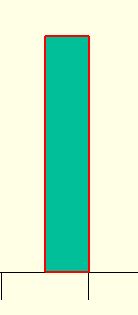
And here is the code of this piece
translate ([35,0])
square ([5,27]);
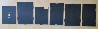
I have cut the pieces of the press fit kit using the laser cutter in the same way that I have cut the box. I have followed exactly the same steps. Here are the pieces after cutting
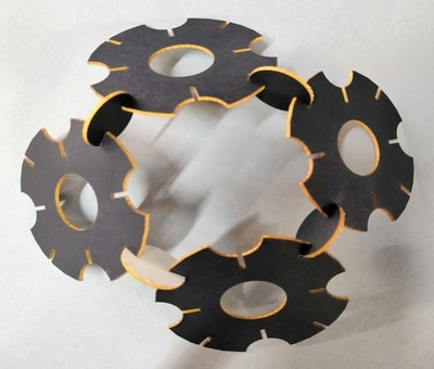
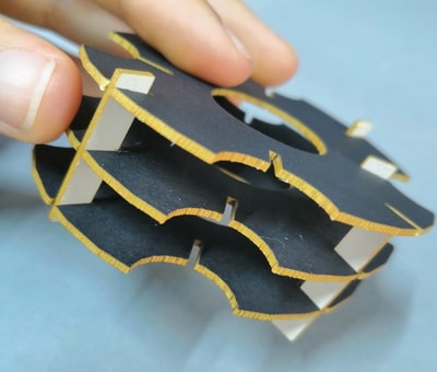
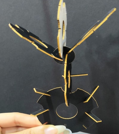
I have created multipule shapes out of those pieces, here are some
Here is the original files:
Moving to my second press fit kit, I have designed it using Rhino and Grasshopper.
.jpg)
.jpg)
I took the dolphin image from the internet and trace it and place it in the middle of each piece. Here are the pieces after I cut them
.jpg)
Vinylcutter
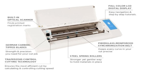
The Vinylcutter used in this assignment is Silhouette Cameo 2 which is an electronic cutting machine that can be plugged directly into the PC via a USB cable exactly like a printer. However, it uses a small blade to cut paper, cardstock, vinyl, fabric and more up to 12in wide and 10 feet long. The machine comes with Silhouette Studio software for cutting and printing the desired shapes and objects. Also, the machine comes with a 12” Cutting Mat to support the cutting media. The figure below shows the basic parts of the Silhouette CAMEO® 2
With the vinyl-cutter I have designed stickers for my laptop. In fab lab Bahrain we use the Silhouette machine, so my stickers were designed in Sihouette studio. Here are the steps I followed:
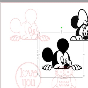
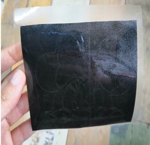
1- Choose the image that you would like to print. I chose the following from the internet.


2- Connect your machine to your PC using the USB wire, then open Silhouette studio from your PC.
3- From the top left, click on File > Open > then import the image.
4- From the tool bar on your right side, click on the fifth icon from the top to open the trace panel.
.jpg)
5- Click on Select Trace Area and draw a square around your object.
6- Choose the trace preview “Outine”.
7- Edit the scale (I set it as 37) so the yellow line covers all the area of my image.
8- Finally, from the trace style, click on trace.
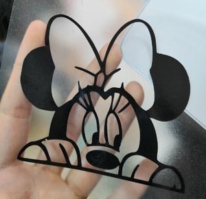
9- after you are done, check that there are no missing parts in your drawing by pulling the image away from the trace.
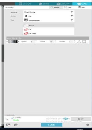
10- Now you are ready to cut your sticker. Click on Send from the top right > then choose the material that you will cut > select the action to “cut” > the parameters of speed, force and passes will be shown > after all the settings confirmed, click on the “send” button and your machine will start cutting.
The following video shows the machine while cutting:
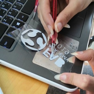
The next step now is to transfer your stickers to somewhere. For me, I have sticked them on my laptop following these steps:
1- First, cut a vinyl transfer sheet with the same size of the sticker.
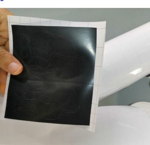
2- Second, place your sticker on the vinyl sheet to ensure that all parts will be sticked excatly at the same place.
3- Third, slowly remove the unwanted parts.
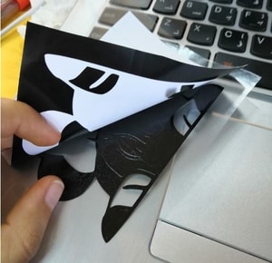
4- Fourth, your sticker will be on the vinyl transfer sheet.
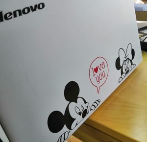
5- Stick your design to the surface you want. I sticked it on my laptop.
Group Assignment
To check the full page please click on the link here.
As a part of the group assigment, I have worked on and designed a comb for the matboard material. The purpose of this comb is check different sizes and see the best size that fit the materail. So, the first step I did is measuring the thickness of the matboard and I found it 2mm. Then, within openSCAD, I have designed the comb with different teeth sizes, starting from 1.95 mm to 2.40 mm with intervals of 0.05 mm. Here is the design as well as the code of it.

x= 75;
y= 30;

//to test the material thickness
difference(){
square ([x,y]);
translate ([68,0])
square ([2.40,15]);
translate ([61,0])
square ([2.35,15]);
translate ([54,0])
square ([2.30,15]);
translate ([47,0])
square ([2.25,15]);
translate ([40,0])
square ([2.2,15]);
translate ([33,0])
square ([2.15,15]);
translate ([26,0])
square ([2.1,15]);
translate ([19,0])
square ([2.05,15]);
translate ([12,0])
square ([2,15]);
translate ([5,0])
square ([1.95,15]);
}
After designing the comb, I have cut it using the laser cutter and do the testing.
.jpg)
.jpg)
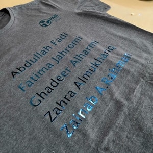
I also worked with my colleagues on a t-shirt. We designed a t-shirt with the fab academy logo and our names. I wrote our names in the Silhouette studio and worked on the logo. I was the one who was dealing with the software side and everyone else had different task. At the end we successfully made our t-shirt. Here are some pictures.