Individual Assignment
For the individual assignment I will design a hat module to connect different environmental sensors as input data, that will be attached to a Fabduino board.
I chose this board as it may fulfill all my future needs along the project in terms of pin connections, data processing in real time, provisional data storing and easy to get in most of the cases.
So the assingment will include Features, Design, Production and Programming of both:
- Fabduino (11.1.)
- Hat shield (11.2.)
11.1. Fabduino (Fabkit v.0.4)
This model is the most similar open source board regarding the Arduino UNO, so it can be easily updated and modified with extra shield-boards to add new functions and components in a sandwich structure. This is an interesting idea for connecting further output displays, sensors, or communication boards.
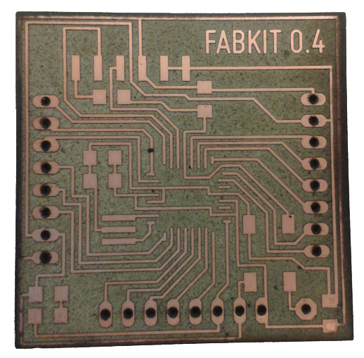
Fabkit v0.4 example
11.1.1. Controller: ATMega328P
The microcontroller used for the Fabkit v0.4, as the one used for the Arduino UNO, is the ATMega 328p.
This processor is much more powerful and versatile than the ATTiny44 microcontroller I used for the Embedded Programming assignment. On the following table we can see the main differences between both of them:
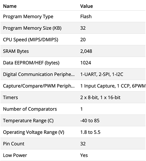
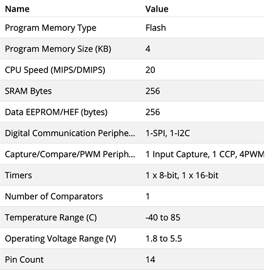
ATMega328P vs. ATTiny44 specifications
As a conclusion we could say the ATMega328P board can process way more data and do it faster than the ATTiny44 (PMS and SRAM: 8 times bigger; EEPROM: 4 times), and more connections at once (18 pins more).
(The ATMega328P pinout scheme can be found at the Board Programming section.)
11.1.2. Fabduino Components
The components I am using for this assignment are listed below:
- Microcontroller: ATMEGA 328P
- Resistor: 499 ohms
- Capacitor (unpolarized): 10 uF
- Capacitor (unpolarized): 1 uF
- Capacitor (unpolarized): 0.1 uF (x2)
- Resonator: 8 MHz
- LED: 1206SMD
- Switch: 6 mm
- Header: 6 pin
- Pin header: 8 pin
I chose to work with a ATMEGA 328P controller to have enough data space and power to process many sensors and sources of info at once. And also the DHT22 over the DHT11 as its much more precise in terms of obtaining the data on a range of decimals of ºC and humidity %.
11.1.3. Fabduino Board design
Then I will design my board on Eagle. First I will check if all the components I need are indeed included in the downloaded libraries. Then in Eagle's schematics, I set all the components, connections, tags and values to create the Fabkit board.
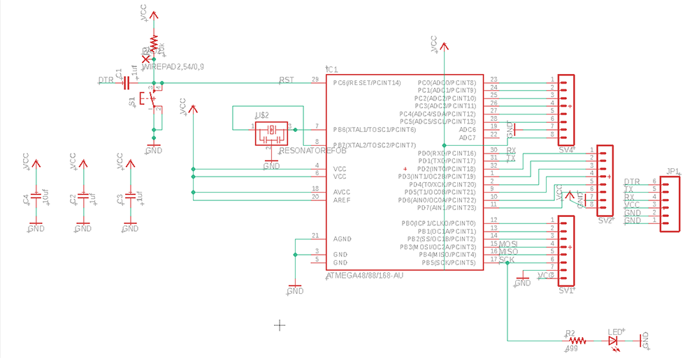
Then switching to Eagle's Board module, I finish setting the connections, and placement of the different elements. This is how it should look
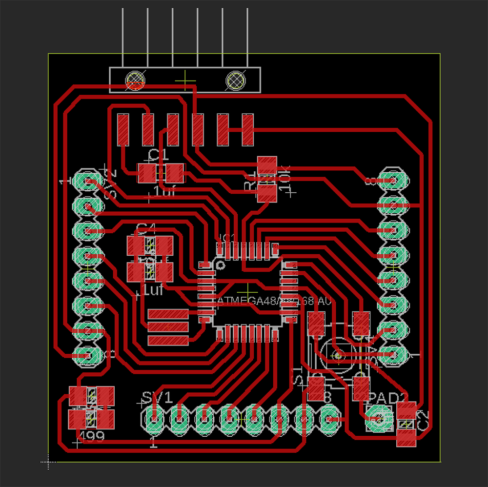
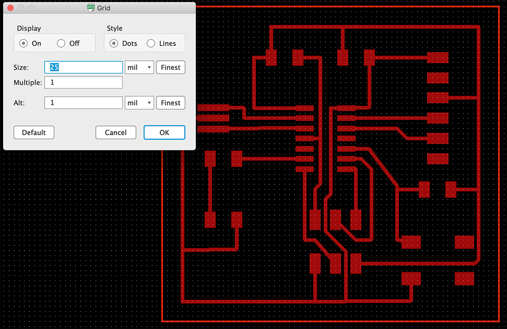
As all the elements are placed very close to each other, it is highly recommended to adapt the grid size so that the distribution is not so restricted and paths can be set easily.
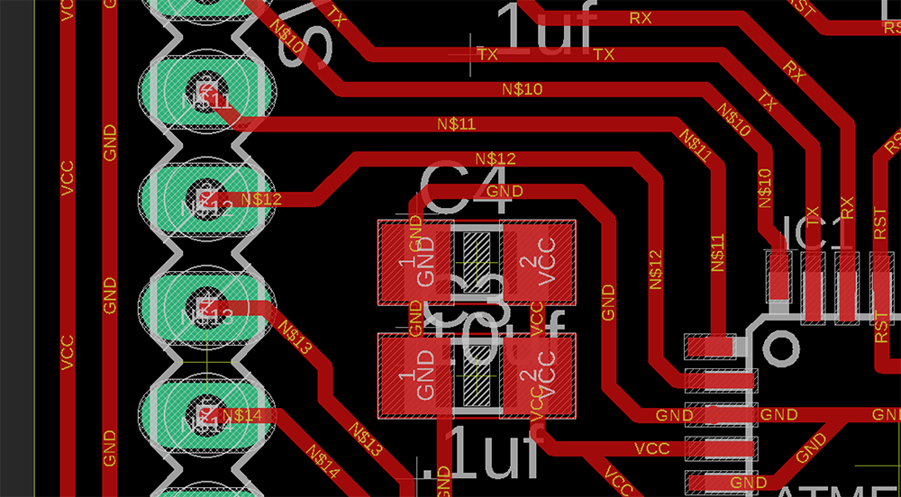
To prevent fails on the board production or connectivity, it is better to avoid 90 degrees angles in paths, so turning them into chamfers may help in the future.
As this board design includes drilled connections to plug external pins, the process of producing the board will be different from the previous works. So, there will be 3 different .png files to prodjce the board:
- The inner milling drawing, activating the paths and pads' layers (without the drilling holes).
- The drilling holes drawing, just activating the pads' layers to know the position and diameter of the holes, filling them in Photoshop and removing the pads from the drawing, so there will just be all the white dots.
- The outer cutting drawing, creating the outer line in Photshop with a 16px thickness line.
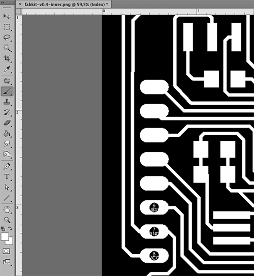
The first inner milling file will be set for a 1/64 endmill, and holes-drilling and outer cutting files with 1/32 endmill. The files are shown below:
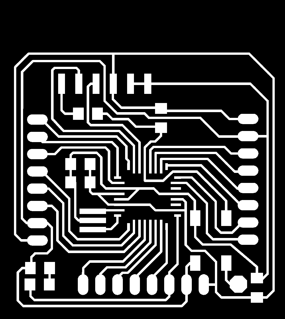
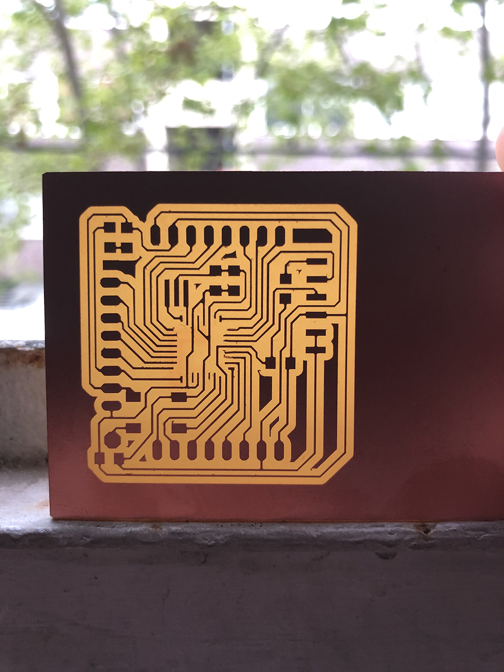
Inner milling file.
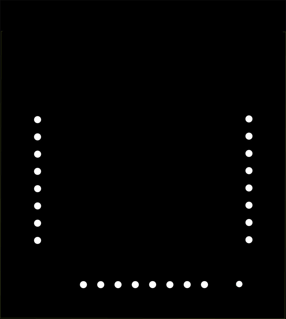

Drilling holes file + Outer cutting file.
11.1.4. Fabduino Board production
After getting the .png files, I can make the .rml files on mods importing them and setting the Roland SRM20 milling machine's parameters for inner circuit, outcut and holes. Then soldering all the elements on the board.
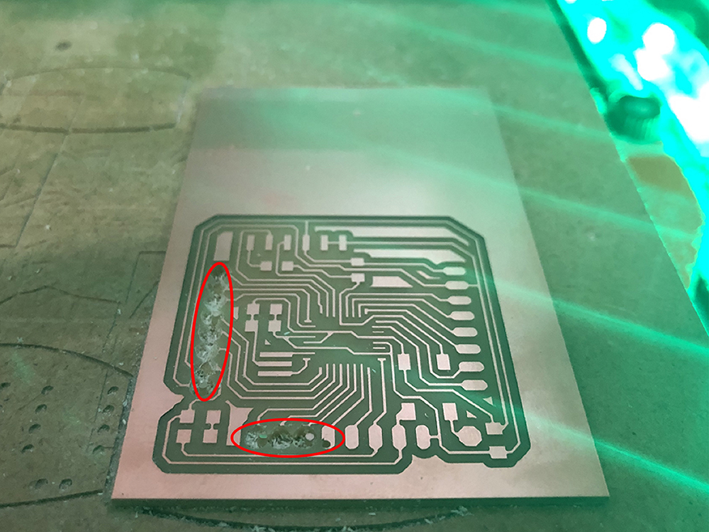
After milling the inner part, that went alright, I had problems drilling the holes on my board. The solution is to invert the drawing in mods, so that the mill doesn't go around the outter lines of the holes, but cut the inner part. So I tried it again inverting the holes' drawing.
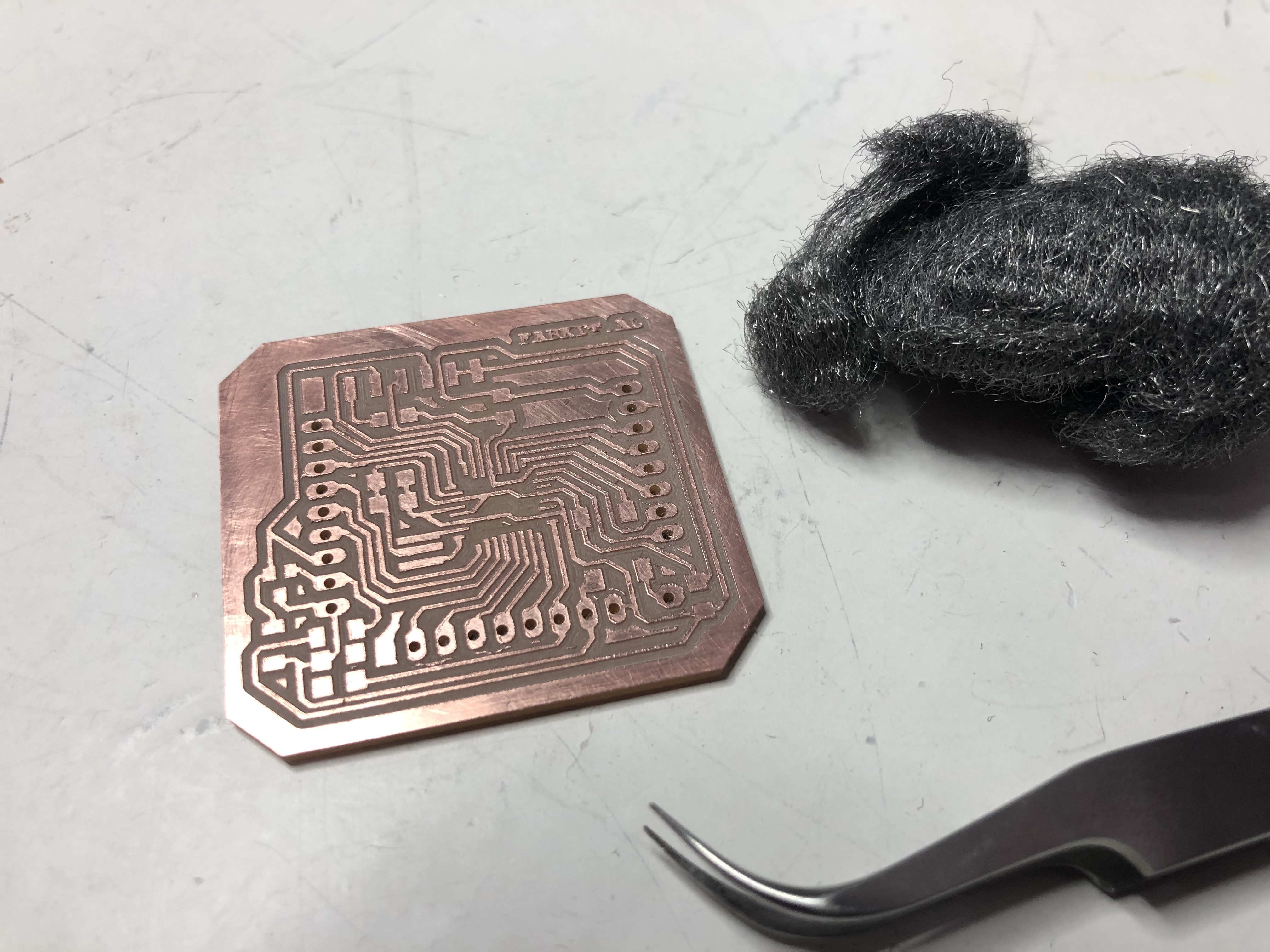
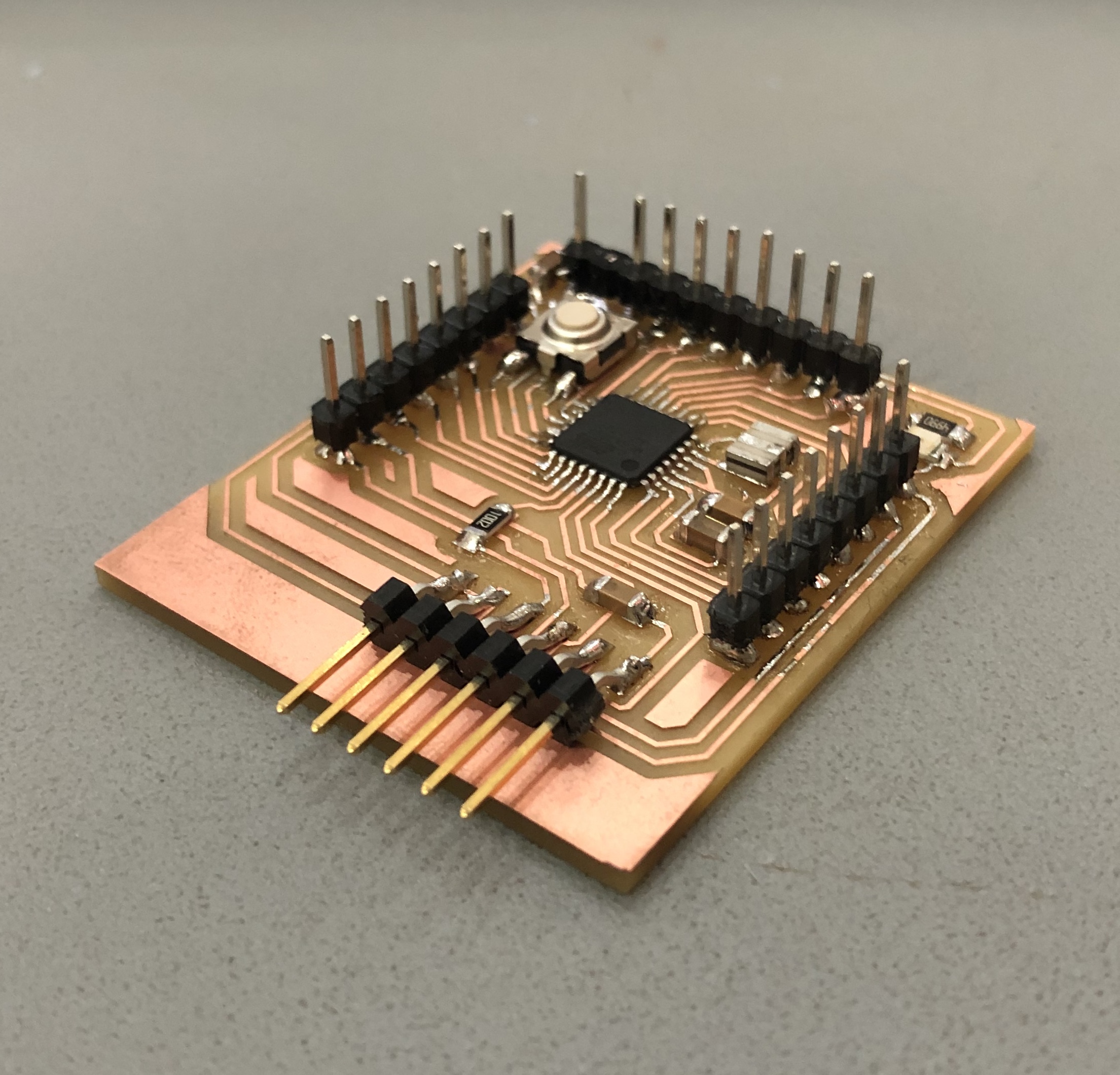
Once I finished milling the first file (inner part) I discovered the microcontroller connections on the board rised up suddenly. This may give me problems in the future, so I milled it again in a lower speed (80% in the Roland machine). And this was the result:
11.1.5. Fabduino Board programming
Before starting to program anything, I checked with the multimeter all the connections in the board, and I had to make several changes in some solderings, as all the elements were very close from each other. Then using the FabISP programmer and the Arduino software I will set a program to read the values from the DHT22 sensor.
First, I need to power my new board to start the process with the FTDI connection, keeping the black cable for the GND pin as a reference.
I also need to check what is the ATMega328P pinout scheme:
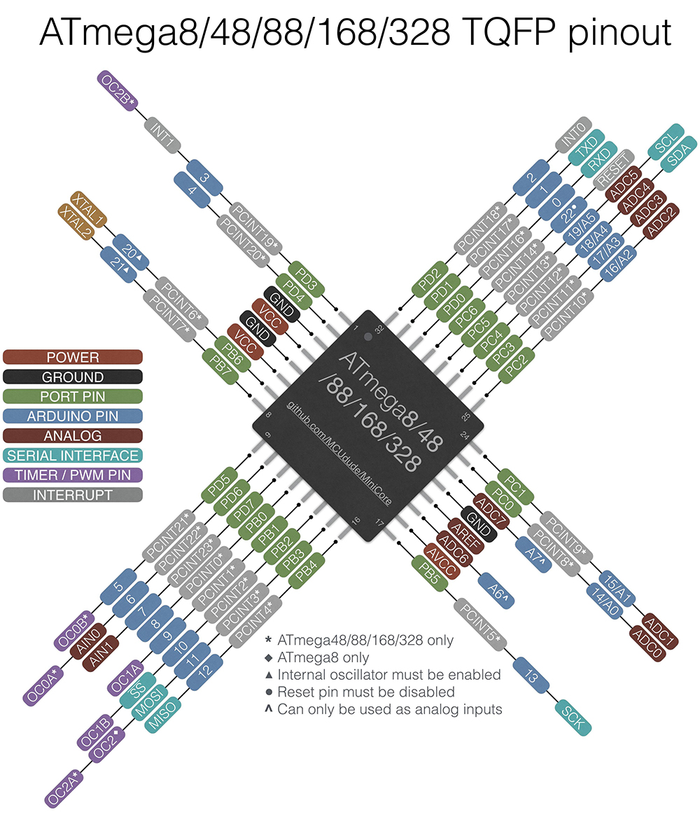
Then from my FabISP board's SMT 2x3 connector, I send all the correspondent wires to the 8 serial pins connecting from right to left: RESET, VCC, GND, SCK (LED), MISO and MOSI.
Before starting with the programming, I will test the Blink example on the board to see if all the settings are fine. But first I need to run the bootloader for the first time to set all the fuses correctly on the board.
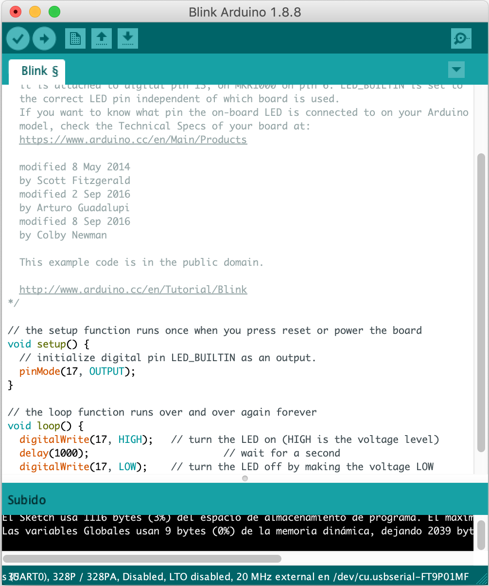
And here the visual proof:
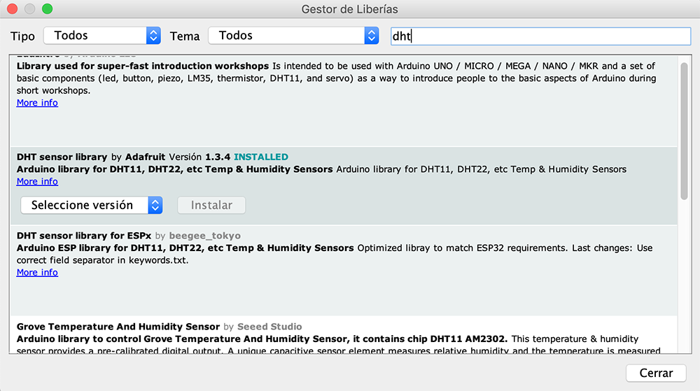
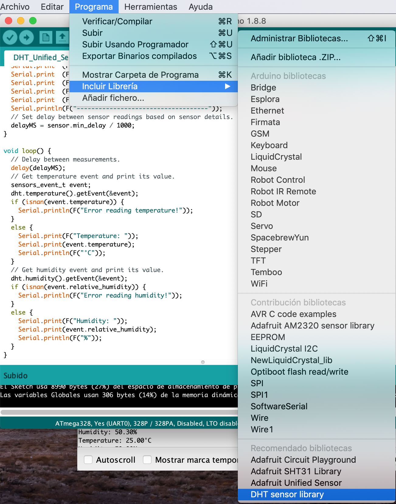
Next, I had to download the DHT sensor library for Arduino:
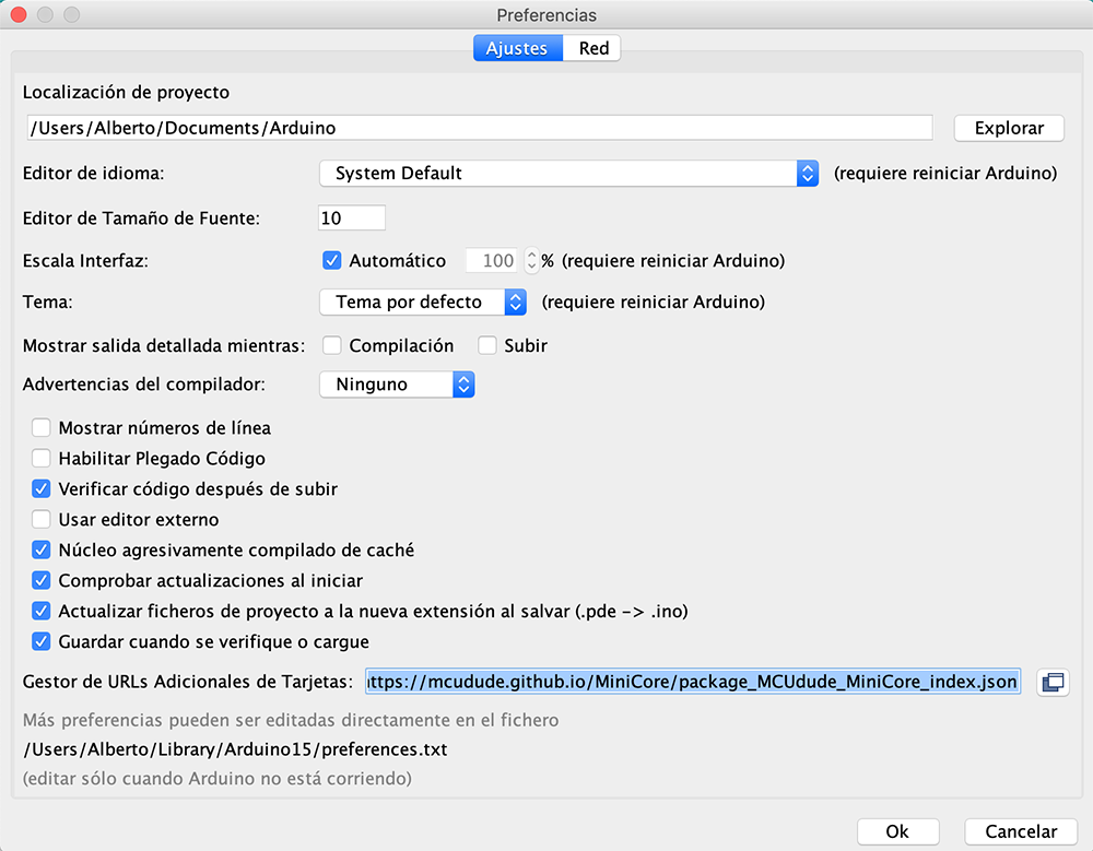
As well as the board config for ATMega328P, setting the next URL on Arduino's Preferences menu on Boards Manager: https://mcudude.github.io/MiniCore/package_MCUdude_MiniCore_index.json
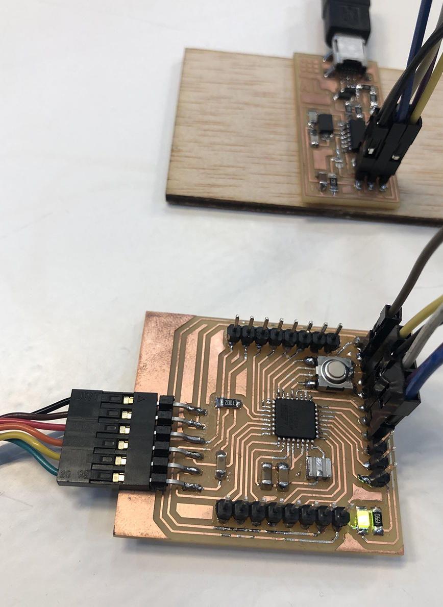
And I tried to start checking the board by programming with simple examples like the blink or the LED+button sketches.
For testing my board with the sensors, I am placing the circuit onto a protoboard first instead of making a single new board for the sensor, as for further exercises of input (anemometer or pluviometer) and output components (lcd display and bluetooth/wifi module) I will need to bring them altogether into the same shield board.
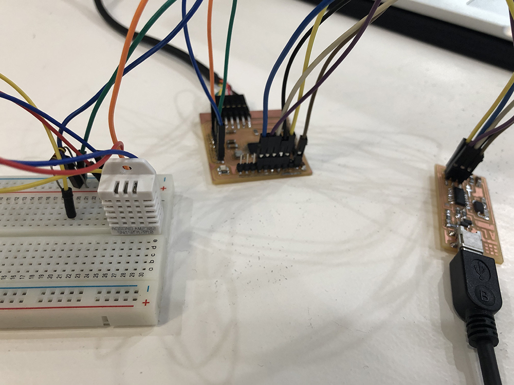
This is the connection I made with my Fabduino + FabISP + DHT sensor and 4.7Kohm Res in protoboard:
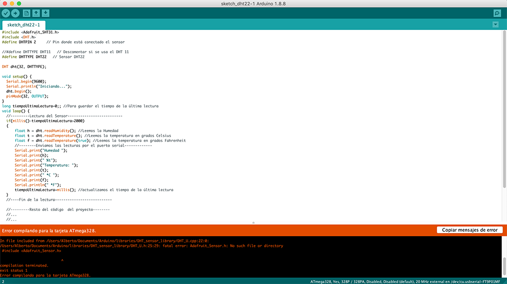
Trying to compile the program I got this error:
Then I noticed I also needed to add an Adafruit Sensor Library from github. So I downloaded and installed it on Arduino.
I programmed the board with the DHT sensor preset testmode to see the first results. But first I had to install the DHT22 library.
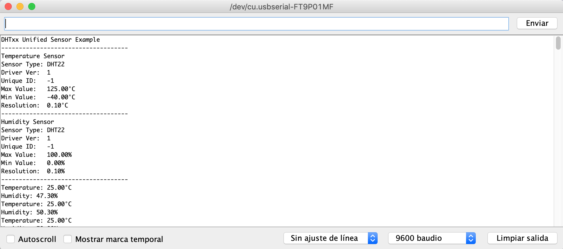
So these were the first results I got with the sensor and the wired circuit:
11.2. Input hat module (shield)
In order to make a personal design of the circuit and not just copy and make the Fabduino board, I decided to make a shield to attatch on top of the Fabduino so that I can connect different devices and components in the future.
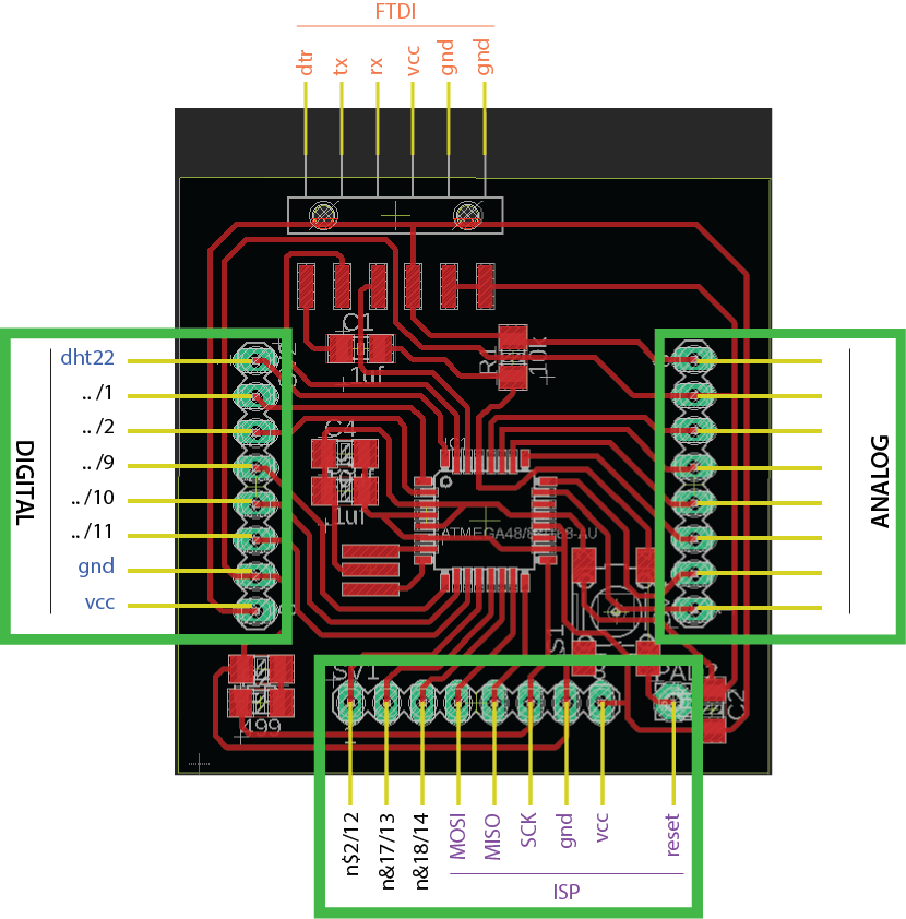
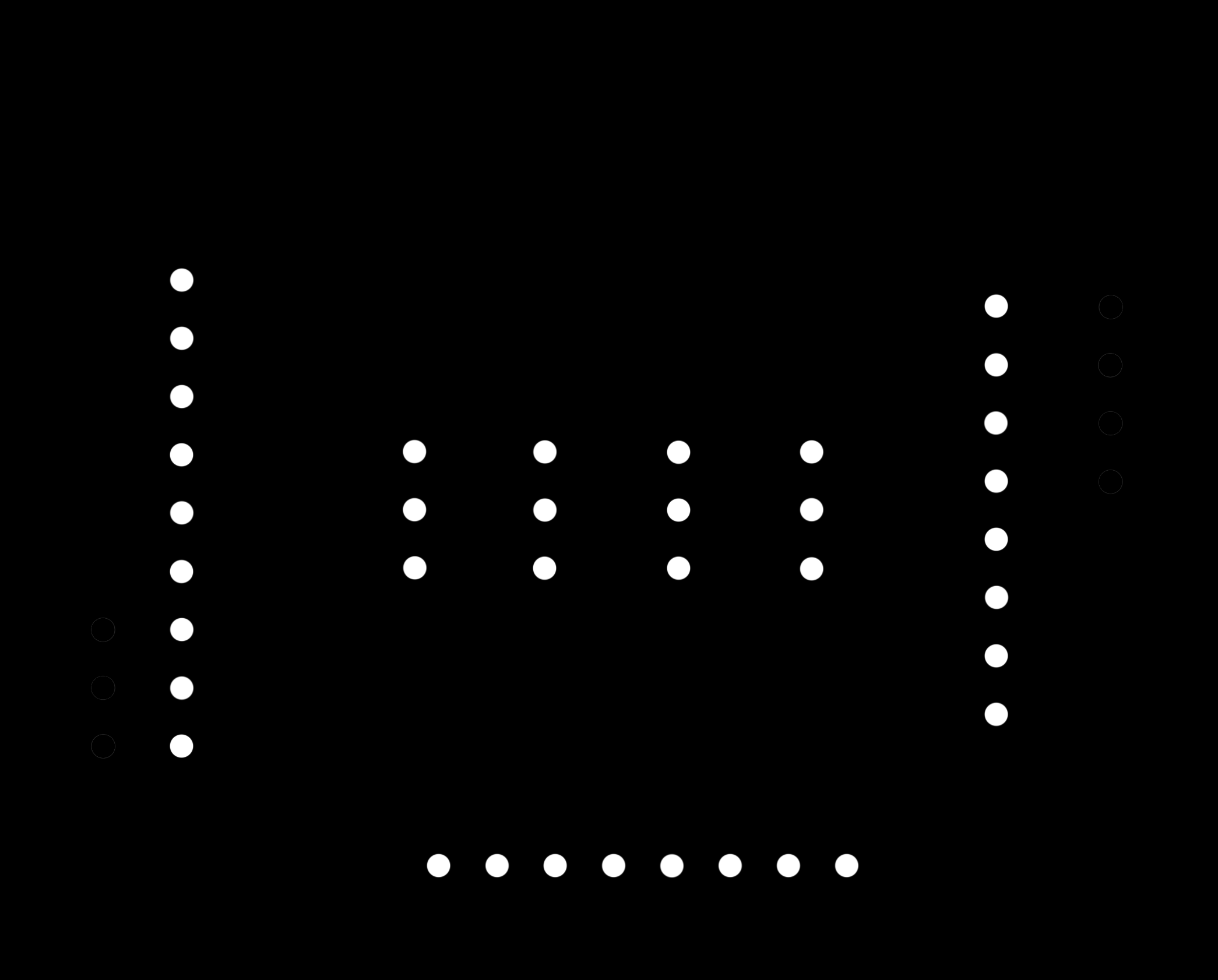
The following shield will be designed to be connected on top of the Fabduino board, so the reference connection pins that should appear on the board are the Digital pin series, Analog pin series, VCC, GND and ISP connections, shown in the picture below:
11.2.1 Shield components
- Temperature + humidity sensor: DHT22
- Resistor: 10 kohms
DHT22 sensor
The first sensor I am using to test the board is the DHT22 temperature and humidity sensor. This component is widely used in many projects and fields, it is easy to plug and solder anywhere, it gets more accurate readings than other models like the previous one (DHT11) and here you can find more different aspects between both models.
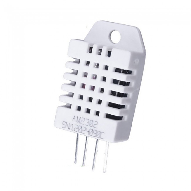
DHT22 humidity and temperature sensor
- Low cost
- 3 to 5V power and I/O
- 2.5mA max current use during conversion (while requesting data)
- Good for 0-100% humidity readings with 2-5% accuracy
- Good for -40 to 80°C temperature readings ±0.5°C accuracy
- No more than 0.5 Hz sampling rate (once every 2 seconds)
- Body size 15.1mm x 25mm x 7.7mm
- 4 pins with 0.1" spacing
11.2.2. Shield design
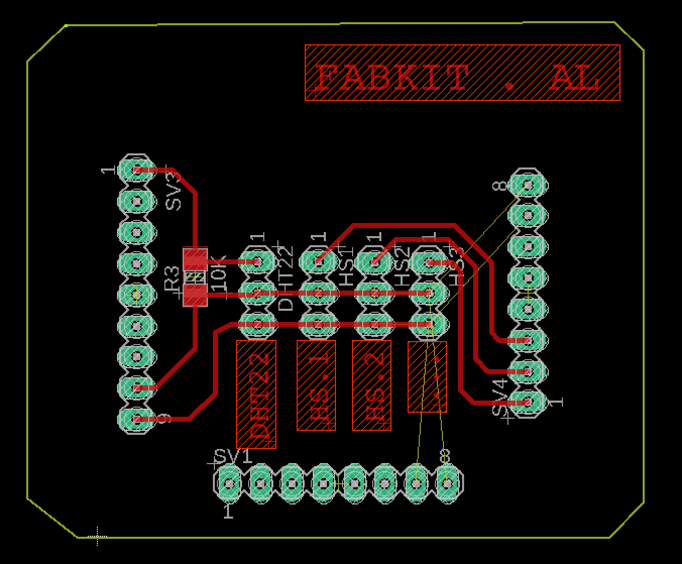
For designing the shield I used the Fabduino file on Eagle to take the same position references as the pin connections I showed before. This way I created 3 parallel paths to set 4 input connections linked to GND, VCC and DATA pins, so that I can use further analog and digital connections on my project. This is the final design of the board I created:
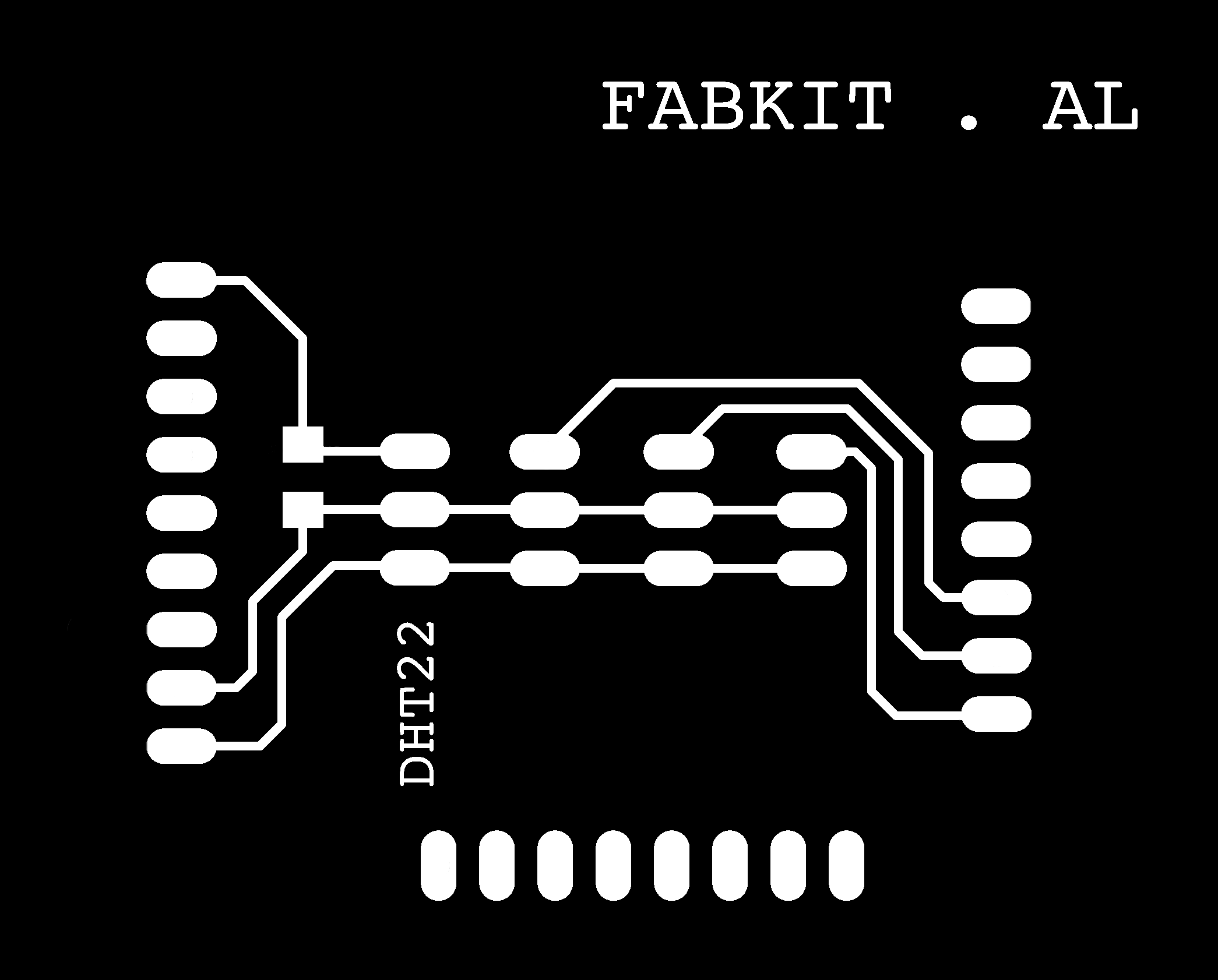
And keeping the same process as on previous exercises, I exported 3 different png images to create the .rml files for milling and cutting the board.

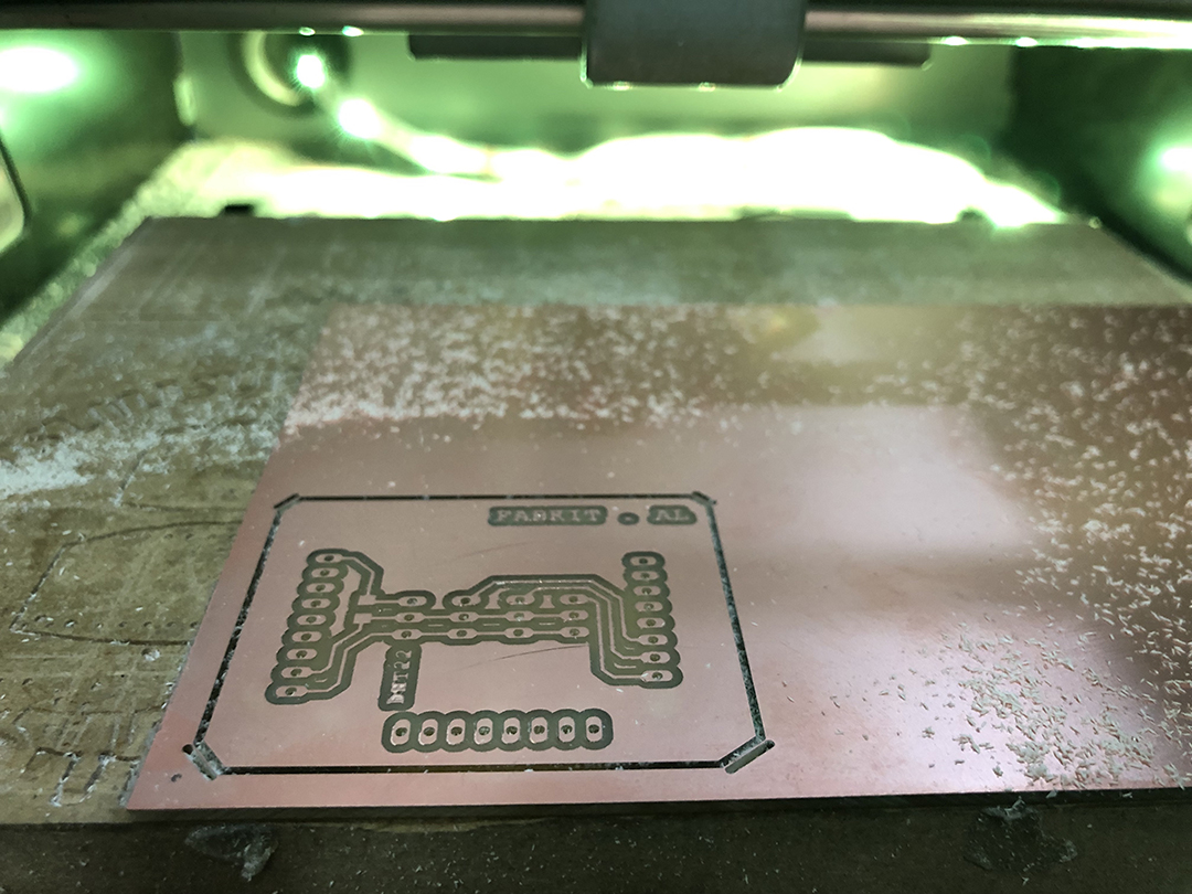
This is the result of the hat input module milling:
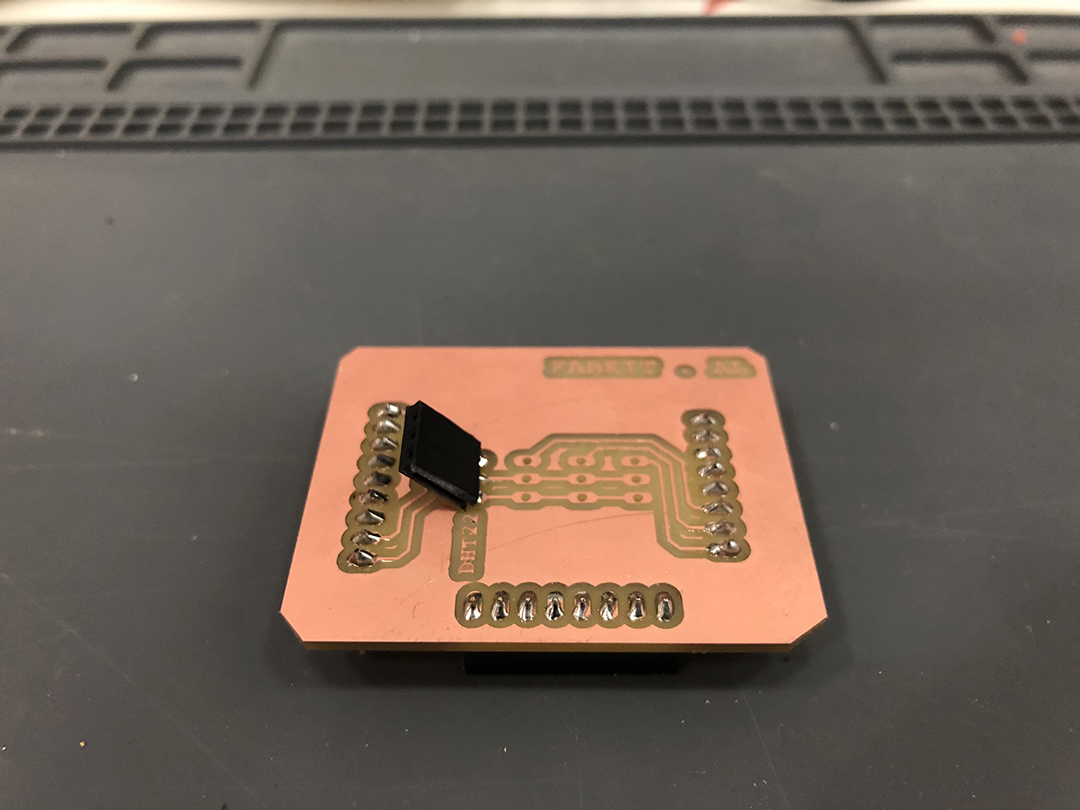
I added space for a 10kohm resistor that some people recommended for the DHT22 reading, but finally it was not necessary. So this is the soldered board:
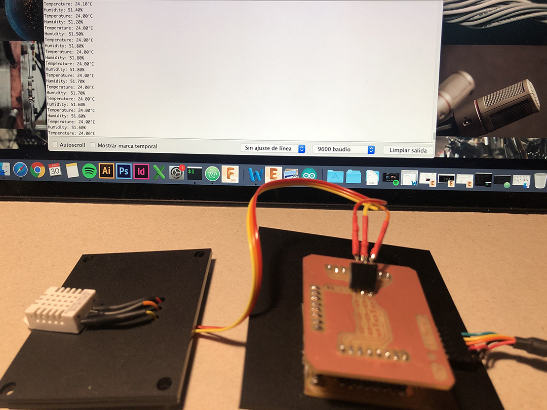
11.2.3. Input data results
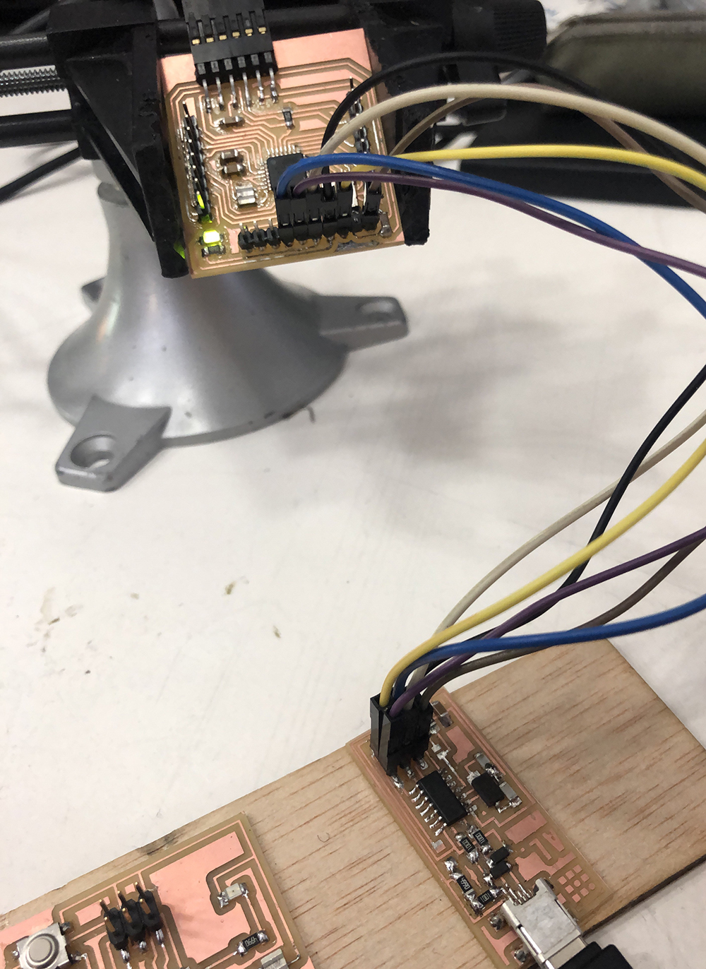
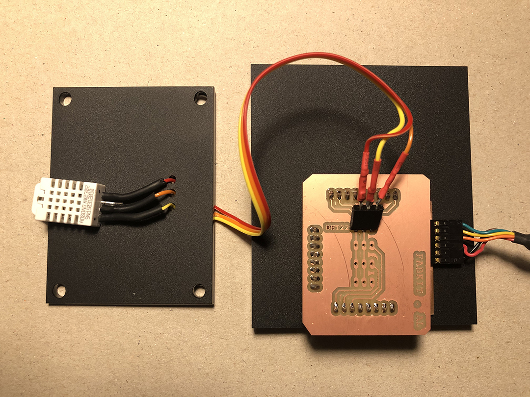
After having tested the board, I just need to connect the DHT22 sensor to the 3 connection pins (GND, VCC and DigitalDATA) on the shield, and the FTDI to the Fabduino to give power to the circuit.
So once I ran the program, I got the following results:
11.3. Further connections
On my final project I will be using two more sensors to measure the windspeed and rain gauge. For these measurements I will need hall effect sensors to count the turning movement of both mechanisms.
I will also need to add a LCD screen to show the data as output information, and a triple pin connection to output GND, 3.5V and 5V power, in case I need to add other elements as motors or modules. For that reason I will need to redesign my Fabduino board, and it is explained on the electronics design part on Wk.20 Project development.