
14.1. Group Assignment: Hello Board - I2C communication
For this week group assignment we decided to connect our HelloBoards with an I2C Bus adapting my scripts. This was an easy and simple way to communicate our boards, we first wanted to use Bluetooth, but we didn't had enough modules or we only had BLE modules and we had some troubles with them.
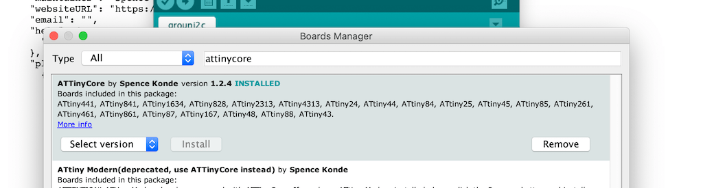
The main objective was to control my Hello Board that has an RGB LED using two hello boards to change the color of the LED. To establish the I2C communication we followed what I just explained up, installing th ATTiny Core by Spencer Conde and using the Wire.h library.
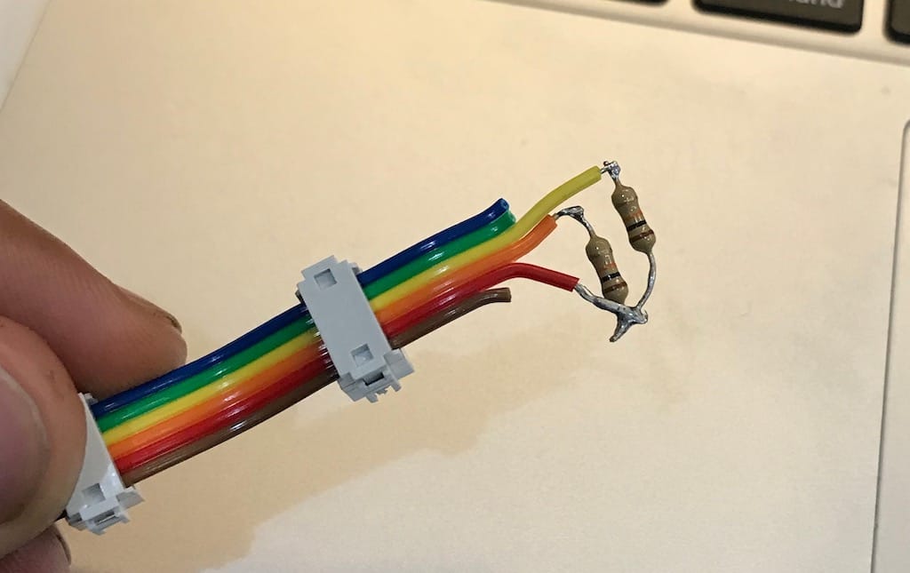
For I2C to work we need two PullUp resistors, like this:
Since we’ll be using Attiny44s and it doesn’t support the Arduino wire library. The first step is to add the AttinyCore from this link to arduino, then install it on the boards manager.
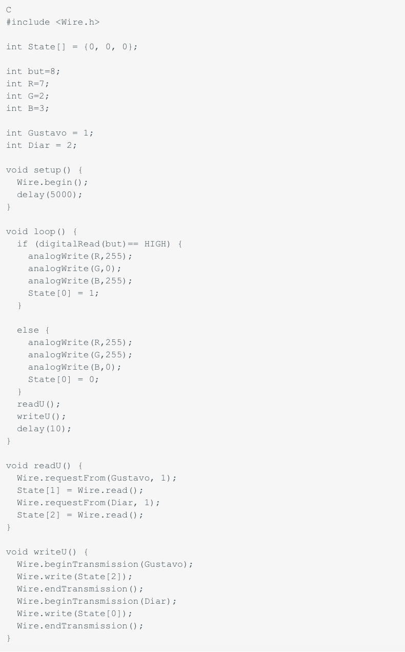
By adapting Josep’s code, we managed to get all boards talking and changing the master’s color when pressing the buttons.
Those are the codes that we used as a master:
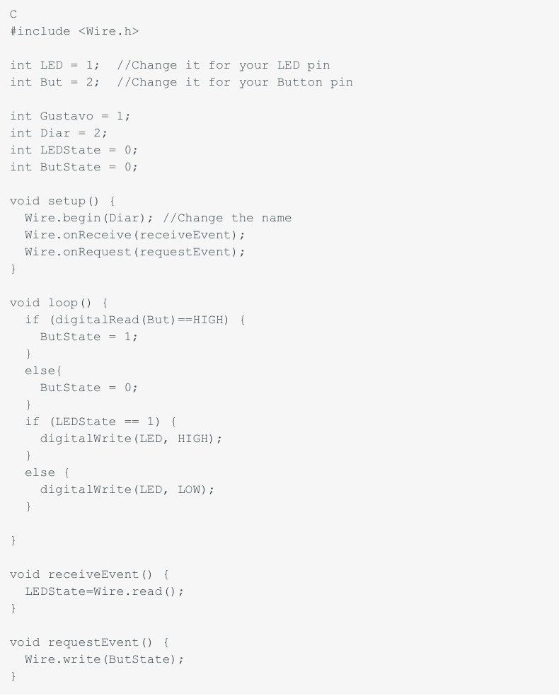
And here is the slave's code:
This is a video showing how it worked:
Group i2c led from Gustavo Abreu on Vimeo.
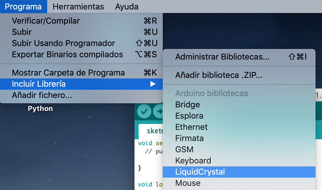
14.2. Individual Assignment: LCD - I2C communication
Related to the assignment on past Wk.12 Output Device, I found an interesting kit that included the LCD screen + I2C interface. So I worked on the I2C protocol to reduce the number of connections of the display from 16 to 4 pins referring to GND, VCC, SDA and SCL. This way it makes it much easier to manipulate, program and connect to any simple board just connecting to ground, power, data and clock.
For that purpose I will need to solder a small board module called I2C Scanner to the LCD display's 18 pins, so that, after programming this module, it can communicate through I2C protocol to my main board (Fabduino+).
There is a simple reference by the display's manufacturer that explains clearly how to make the whole process of programming with the component's library for Arduino.
As the only components on this communication will be between the Fabduino and the display, it will not be necessary to search for the address.
*On last Wk.12 Output Device assignment I could read and display the same way the DHT22 sensor.
First I included the library in Arduino software to set the circuit:
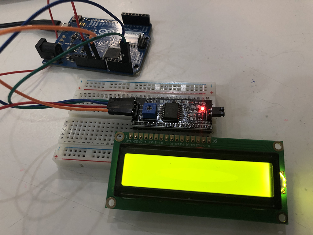
Then I connected first both the LCD display and the module to a wired breadboard and an ArduinoUNO to test if the components are fine:
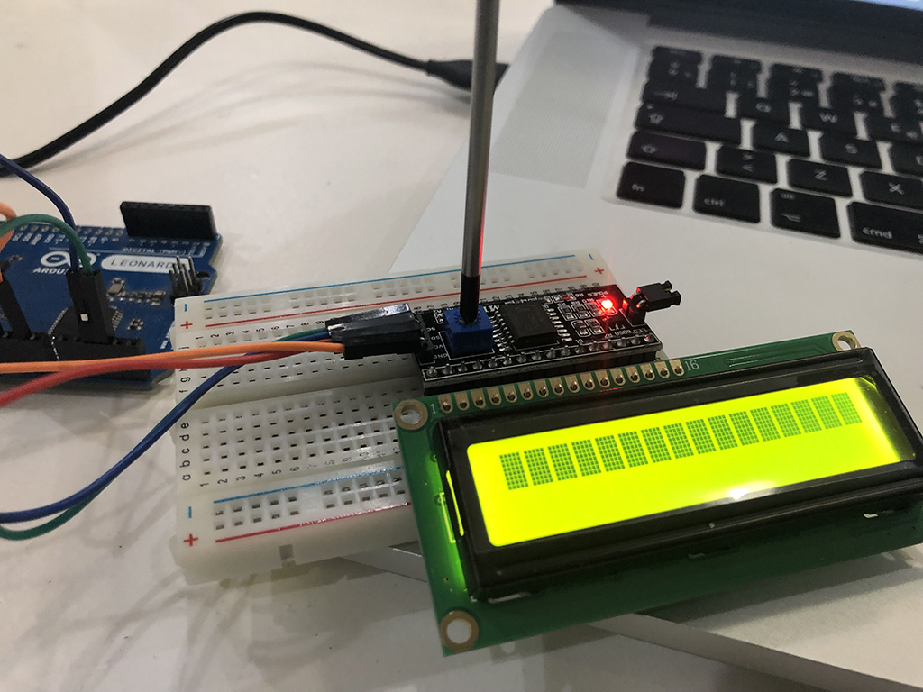
It took me some time to realize that I had to adjust the screen's contrast by turning the potentiometer at the back with a screwdriver:
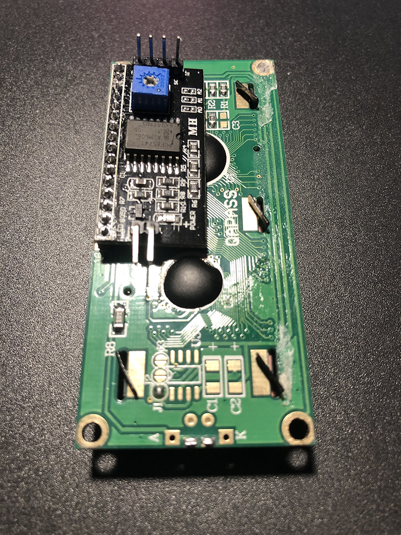
Once I checked all the connections and components were working, I put both elements together as shown below:
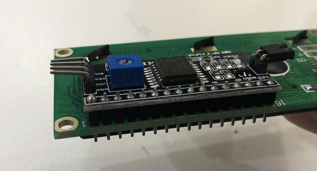
Then I had to desolder the lateral 4 pins 90 degrees connection on the module to replace it with straight ones to get better access to the pins:
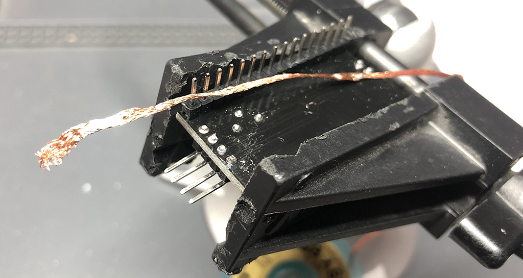
This is the result at the back:
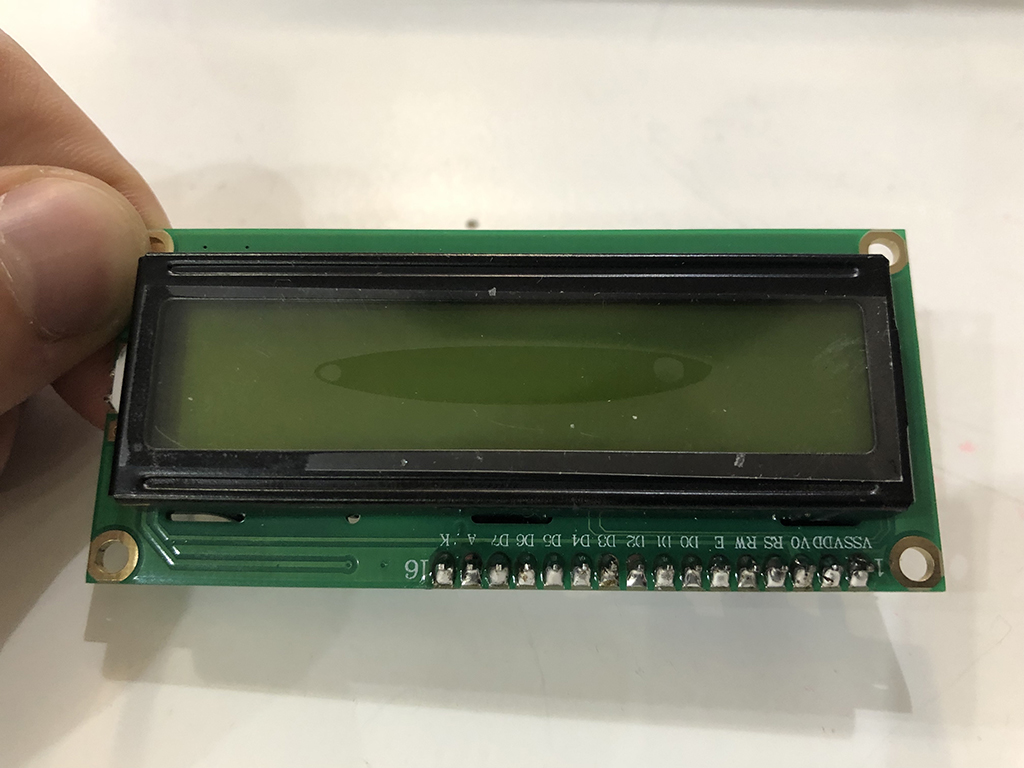
and at the front:
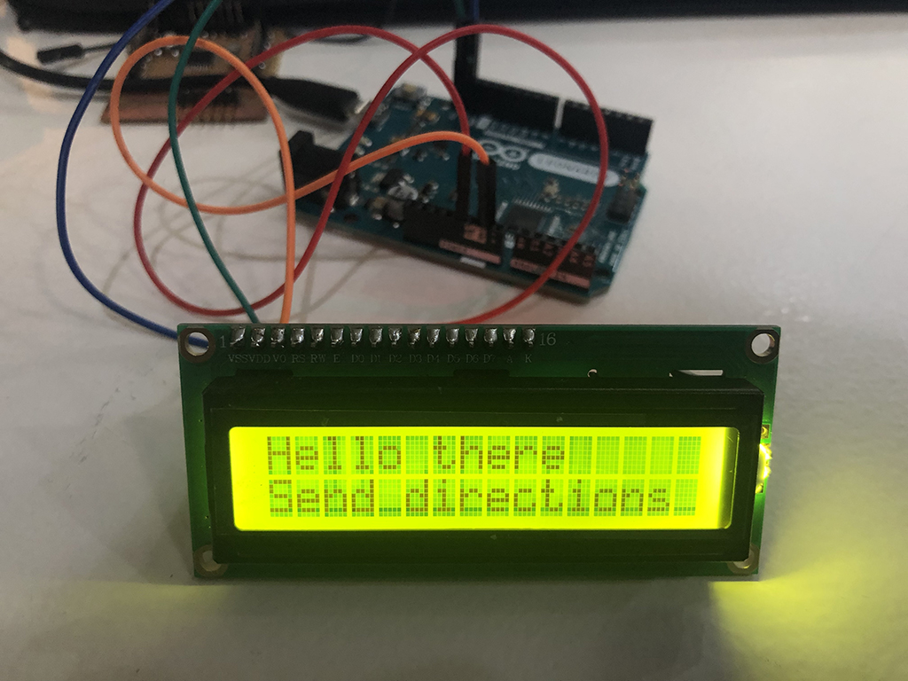
Once I connected the wires from the module to the arduino, I modified the HelloWorld sketch to send a different message to the display. But I got bad readings:
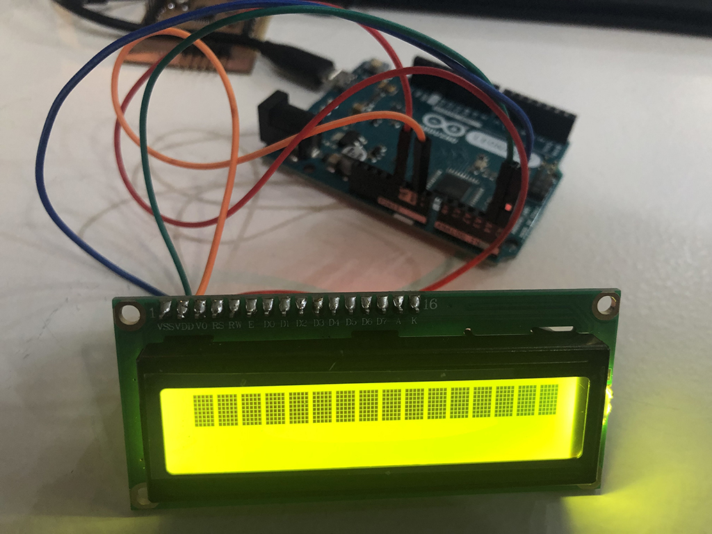
So I had to switch the SDA and SCL pins in the Arduino, that solved the problem and this was the final result:
Wk7-Files
14.3. WiFi communication
WiFi ESP8266 module
Some useful info about the ESP8266 wifi module can be found here, where you can also find how to communicate through serial via wifi.
- The ESP8266 is a low cost Serial-to-WiFi module that interfaces nicely to any microcontroller.
- This board works with both TCP/UDP protocols
- Newer versions use 9600 baud rate, older ones from 57600 to 115200 baud rates
- Easily configured as web server
- It must be powered with 3.3V at most
This is the pinout scheme of the ESP8266:
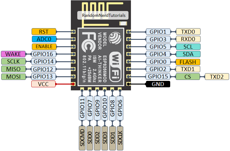
According to this scheme, I can just use one pin as analog input, and the rest could work for digital inputs.
Board's components
- ESP8266 module
- Switch button (x2)
- Voltage regulator 3V3
- 10 kohm resistor (x4)
- 10 uF capacitor
- 4.7 uF capacitor (x2)
- FTDI pins
- 3 pin header (sensor)
- 2 pin header (power)
- 3V3 FTDI cable
14.3.1. Wifi module PRODUCTION
For designing my Wifi module, I took as a reference a board from a zeppelin device created by Edu, one of our instructors:
I removed the components that I didn't need, and added a pin header to connect the DHT sensor to test the data sent by wifi.
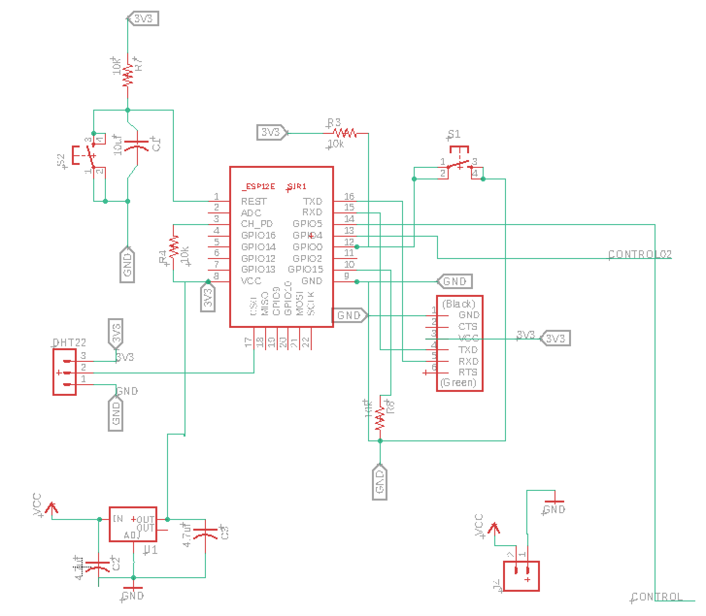
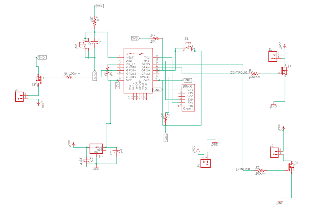
This is how the circuit looked on Eagle:
I got got an error message while placing the capacitor between one of the buttons and the processor, so I had to modify the png file on Photoshop.
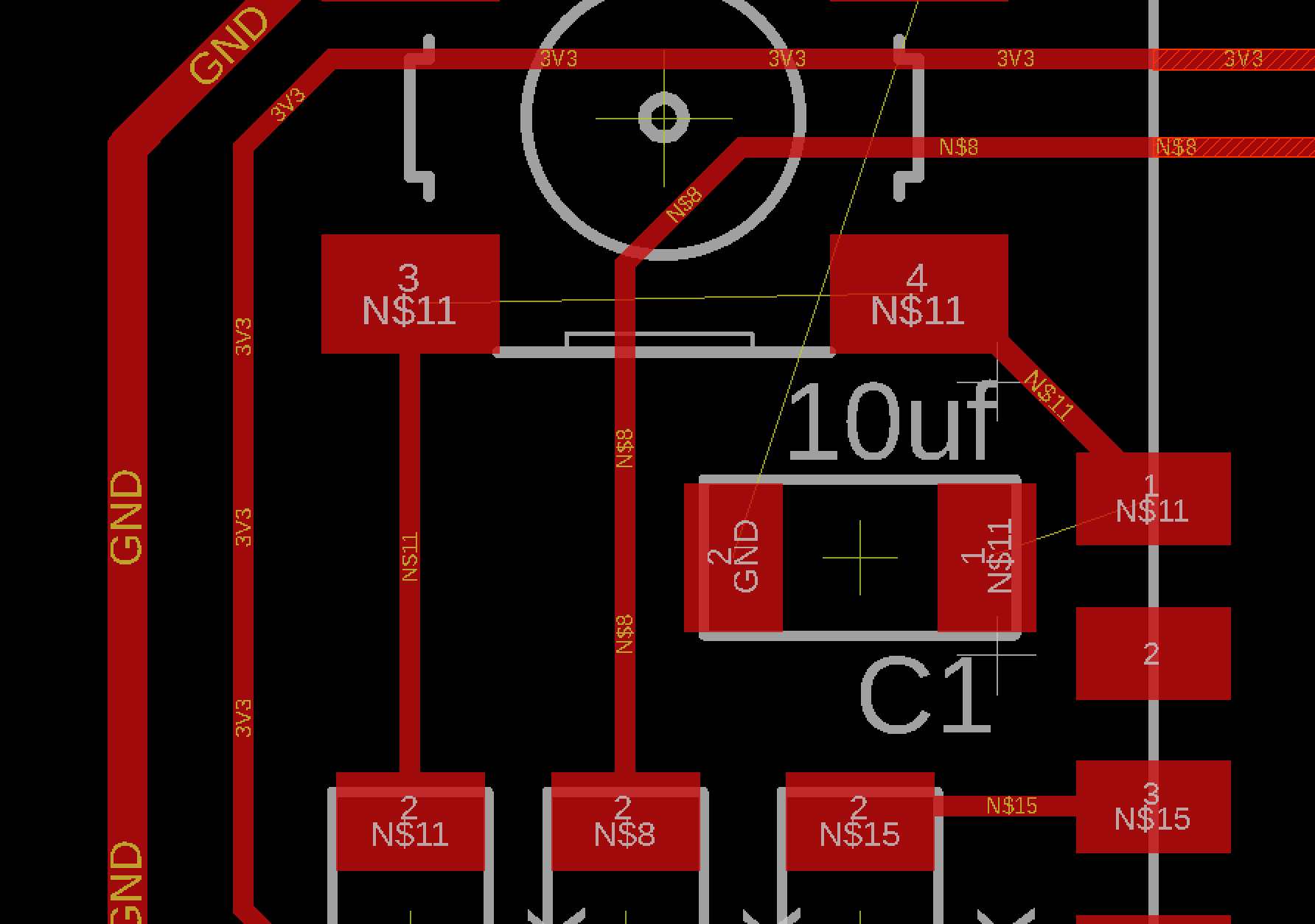
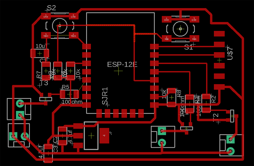
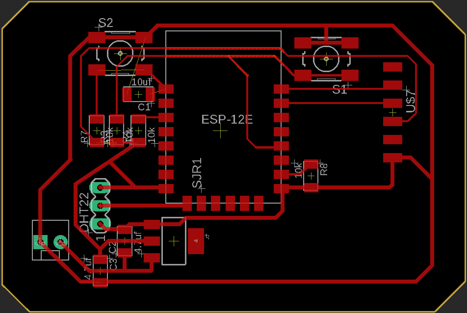
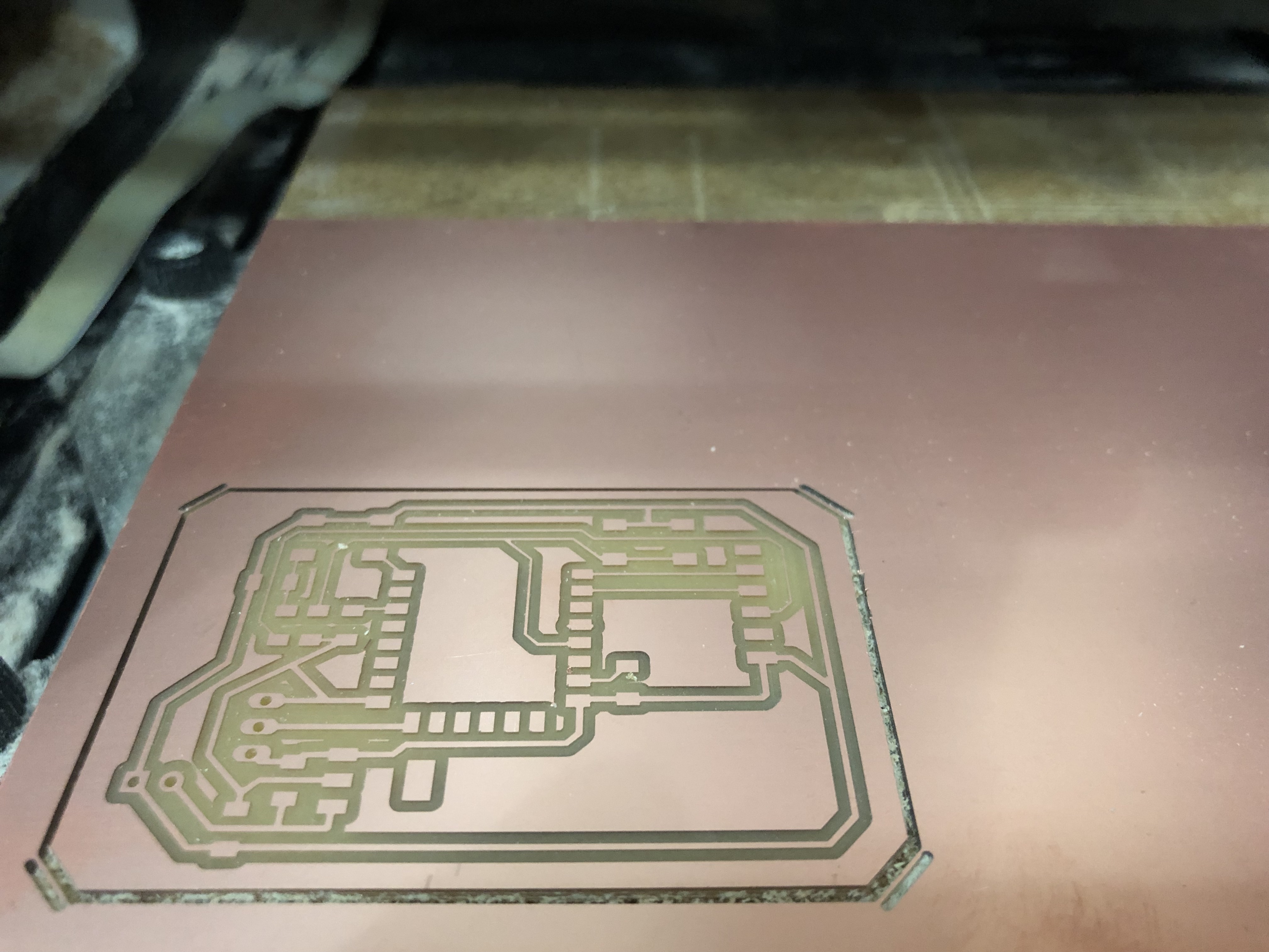
Then I milled the board on the SRM20 machine and this was the result:
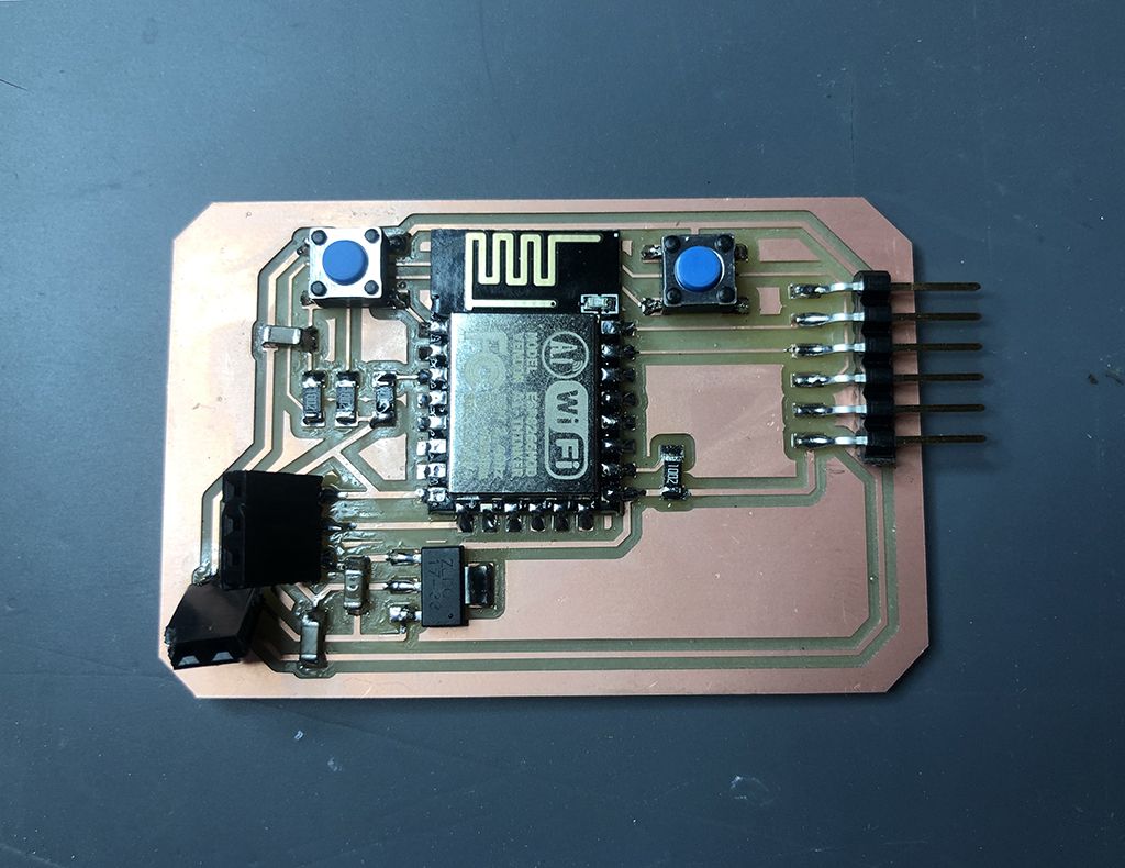
After soldering all the elements, this was the final board:
14.3.2. WiFi module TESING
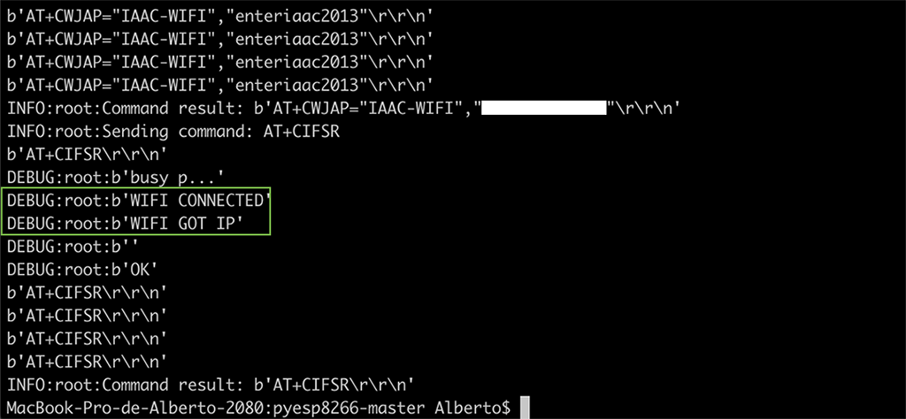
The board will just communicate through serial and it won't allow to flash or program it. I used the program I found on the previous link. The program is ran with a python script included on the folder, and it should be easily executed just by using this command:
python esp8266test.py serial_port baud_rate ssid password
This simply requires including the serial port (/dev/cu.usbserial-FTFO898M), baud rate (115200), wifi address (IAAC WIFI), and password.
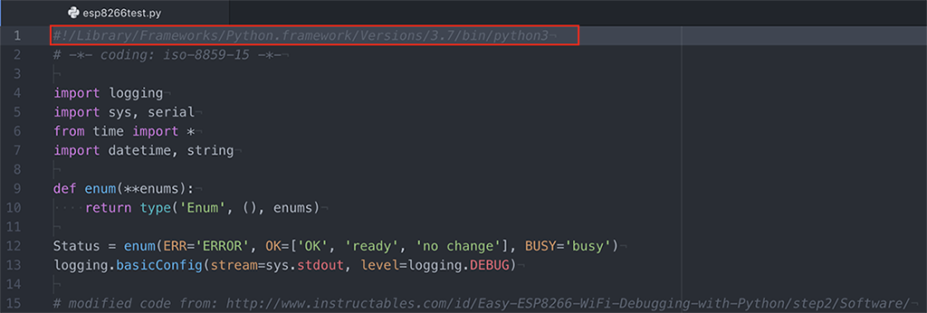
As the script considered a Python 2.7 version and mine was 3, I needed to make some changes on the script according not just to the version, but also defining the serial module.
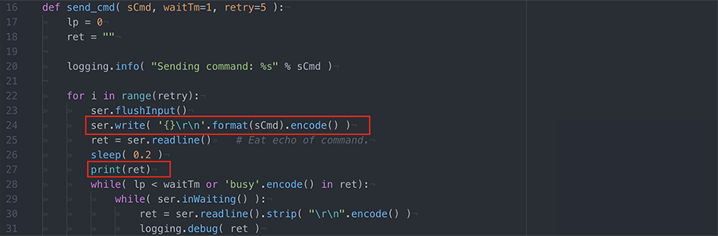
Apparently I had to modify also the unicode strings by encoding the data im writing to serial, so here I found the solution.
After running the program on the terminal once again,
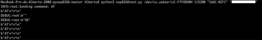
I succeded on the process:
14.3.3. WiFi module as WEB SERVER
For the web server exercise, I am using the server program called esp8266server.py. After making some modifications as I did on the previous code, I could connect to the network but could not send the message to the web server:
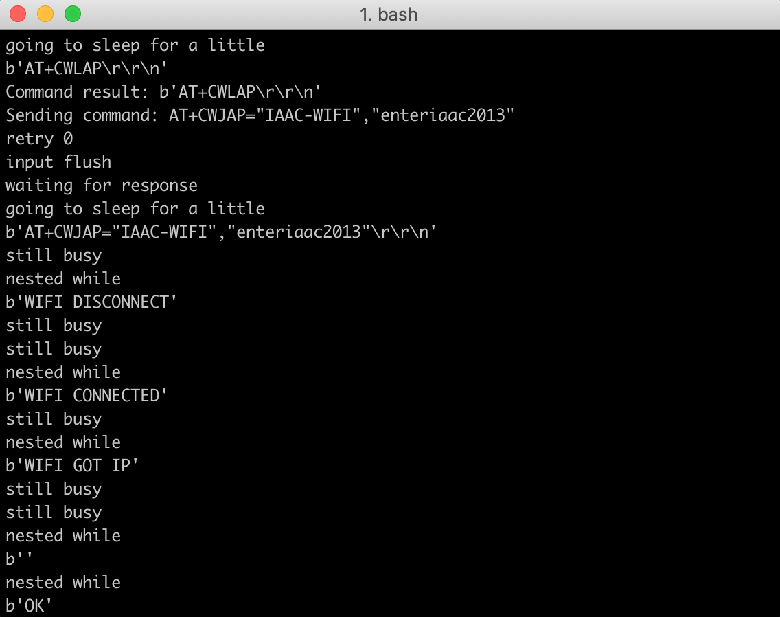
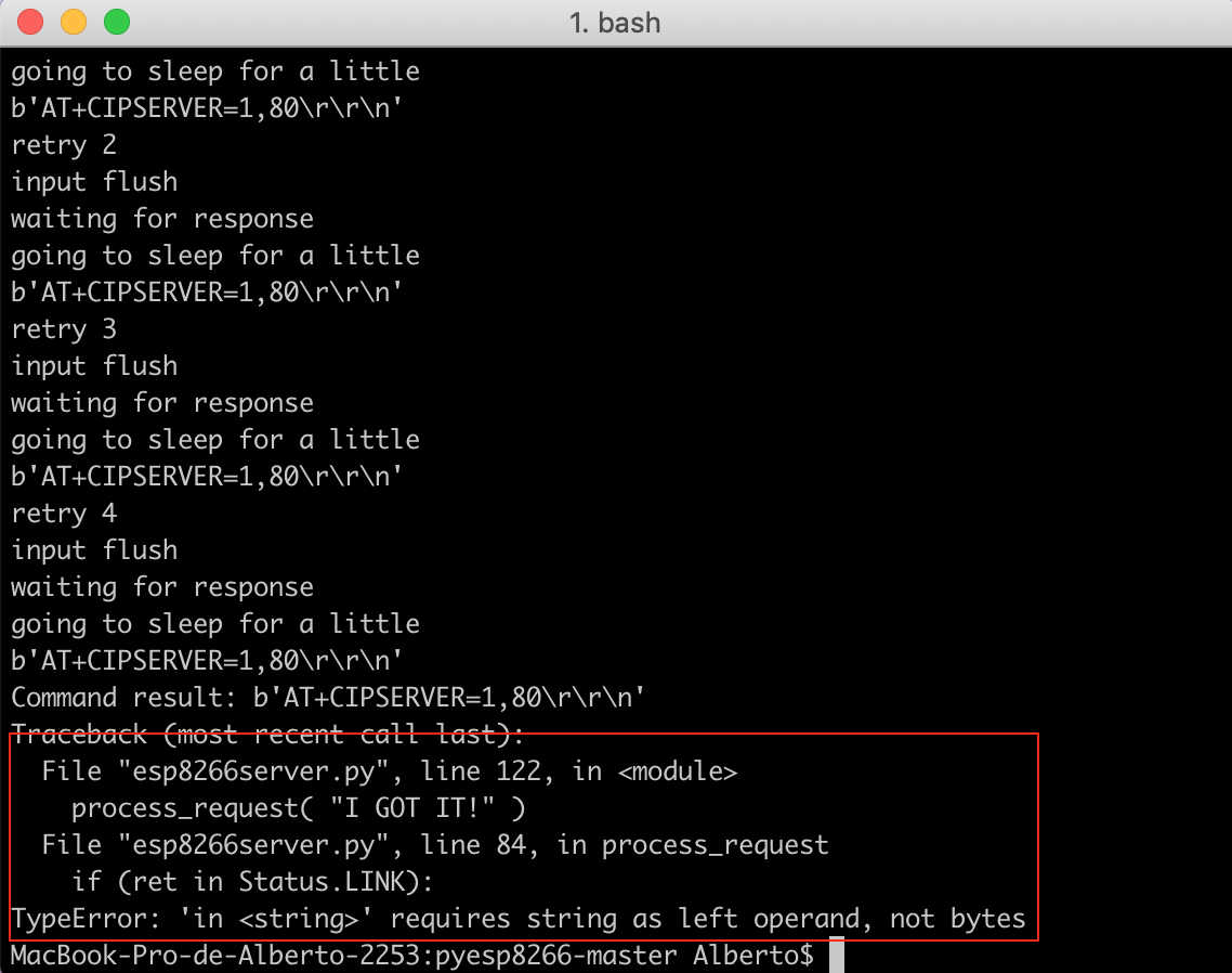
I got the same error as I did before, "TypeError: 'in < string >' requires string as left operand, not bytes".
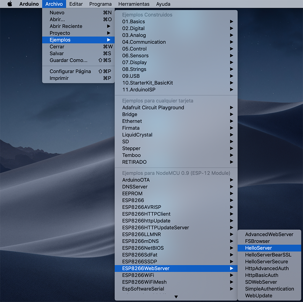
As I didn't manage to fix it, I refused on working with this Python code, and decided to program the board with some Arduino examples. So I chose the Hello server example on Arduino:
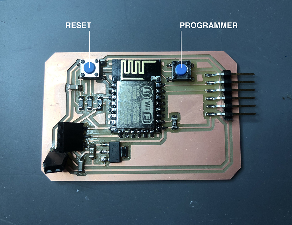
To program the board I redesigned from Edu's model, it's important to mention the 2 buttons' functions of reset and programming:
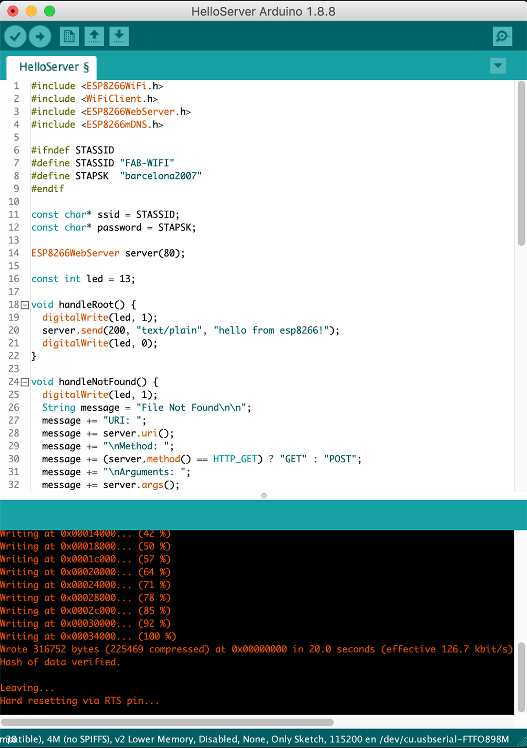
Before running the program, I must define the ssid and password on the code. Then after running, I must press both buttons while compiling the code, then release the reset button while connecting and when it's over, release the programming button and press once the reset button. I should get the following message:
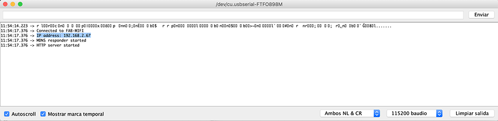
Then I open the serial monitor where I can get the IP address:
I should paste it on my browser's URL bar and get the following message:
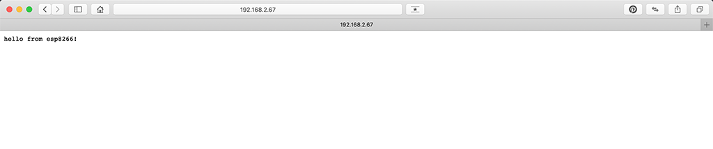
GOT IT!
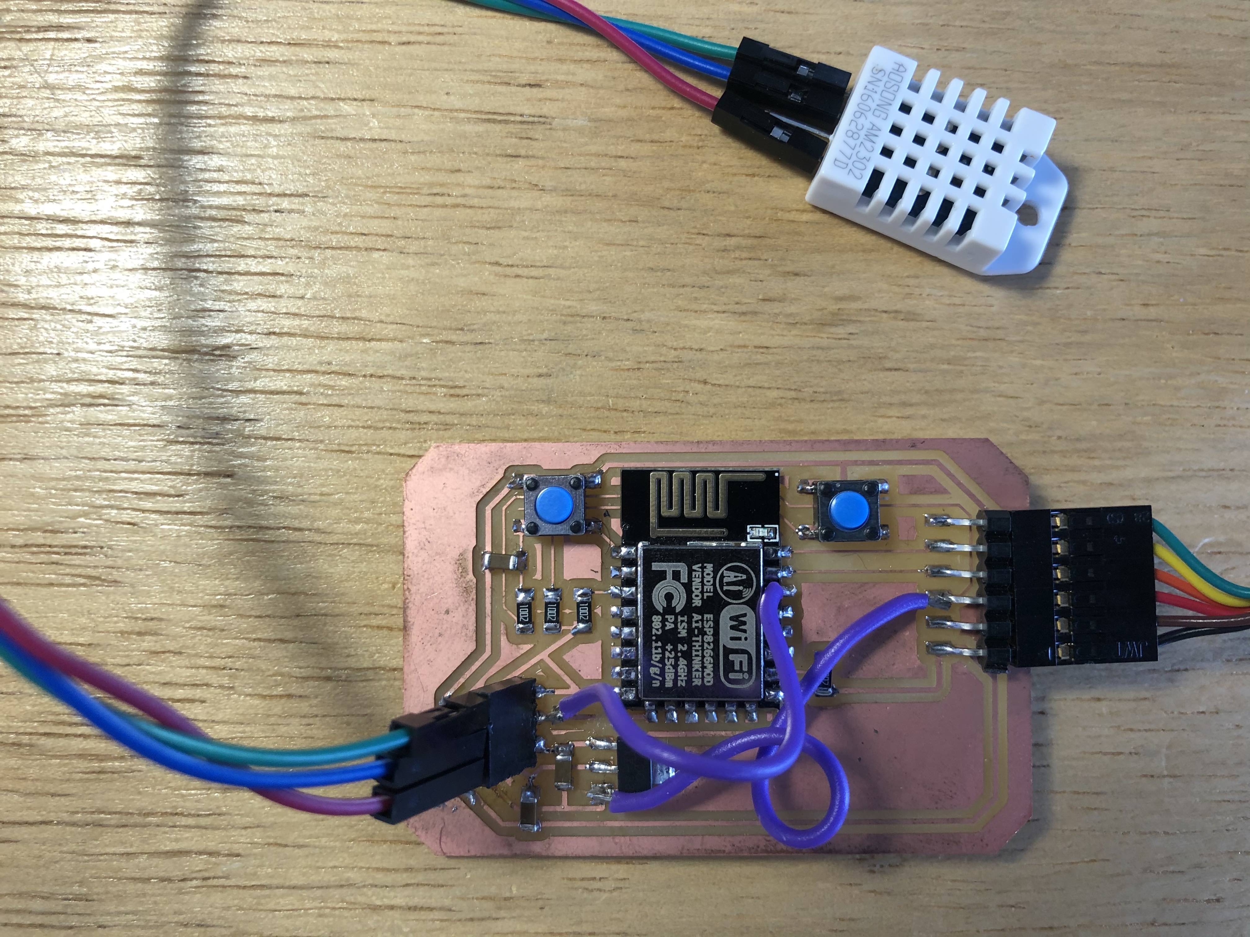
Then I tried to show the DHT22 sensor's temperature and humidity data. But first, after some problems with the power supply connection and the DHT22 data connection according to the ESP's pinout, I decided to use a pair of jumpers to connect the 3V3 between the power regulator and the FTDI, as the Data pin from the DHT sensor to ESP8266's GPIO5 (D1) pin.
For this case I used this tutorial as a reference. The program creates a web server with real time reading of both temperature and humidity data, and displays the info every 10 secs. I had to include the ESP8266 library.
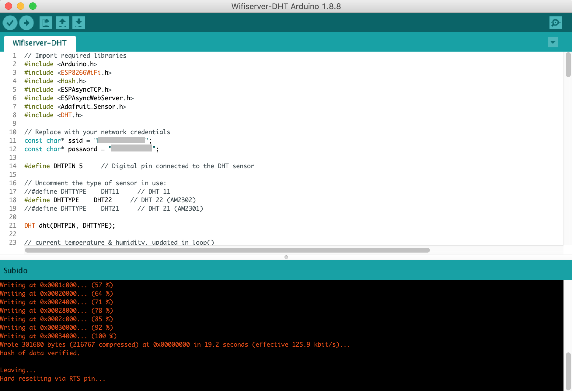
I included the DHT and ESP8266 libraries, and modified the code setting the SSID and wifi password, the data on pin 5, changed the reading and answering delay from 10 to 2 secs. The code includes an HTML part for the message on the answer, so I added my poject's name on the title too. Here I could also modify the text's font, size and color; and also change the logo images on FontAwesome. This is the final code I used:
// Import required libraries
#include <Arduino.h>
#include <ESP8266WiFi.h>
#include <Hash.h>
#include <ESPAsyncTCP.h>
#include <ESPAsyncWebServer.h>
#include <Adafruit_Sensor.h>
#include <DHT.h>
// Replace with your network credentials
const char* ssid = "********";
const char* password = "********";
#define DHTPIN 5 // Digital pin connected to the DHT sensor
// Uncomment the type of sensor in use:
//#define DHTTYPE DHT11 // DHT 11
#define DHTTYPE DHT22 // DHT 22 (AM2302)
//#define DHTTYPE DHT21 // DHT 21 (AM2301)
DHT dht(DHTPIN, DHTTYPE);
// current temperature & humidity, updated in loop()
float t = 0.0;
float h = 0.0;
// Create AsyncWebServer object on port 80
AsyncWebServer server(80);
// Generally, you should use "unsigned long" for variables that hold time
// The value will quickly become too large for an int to store
unsigned long previousMillis = 0; // will store last time DHT was updated
// Updates DHT readings every 10 seconds
const long interval = 2000;
const char index_html[] PROGMEM = R"rawliteral(
<!DOCTYPE HTML><html>
<head>
<meta name="viewport" content="width=device-width, initial-scale=1">
<link rel="stylesheet" href="https://use.fontawesome.com/releases/v5.7.2/css/all.css" integrity="sha384-fnmOCqbTlWIlj8LyTjo7mOUStjsKC4pOpQbqyi7RrhN7udi9RwhKkMHpvLbHG9Sr" crossorigin="anonymous">
<style>
html {
font-family: Arial;
display: inline-block;
margin: 0px auto;
text-align: center;
}
h2 { font-size: 3.0rem; }
p { font-size: 3.0rem; }
.units { font-size: 1.2rem; }
.dht-labels{
font-size: 1.5rem;
vertical-align:middle;
padding-bottom: 15px;
}
</style>
</head>
<body>
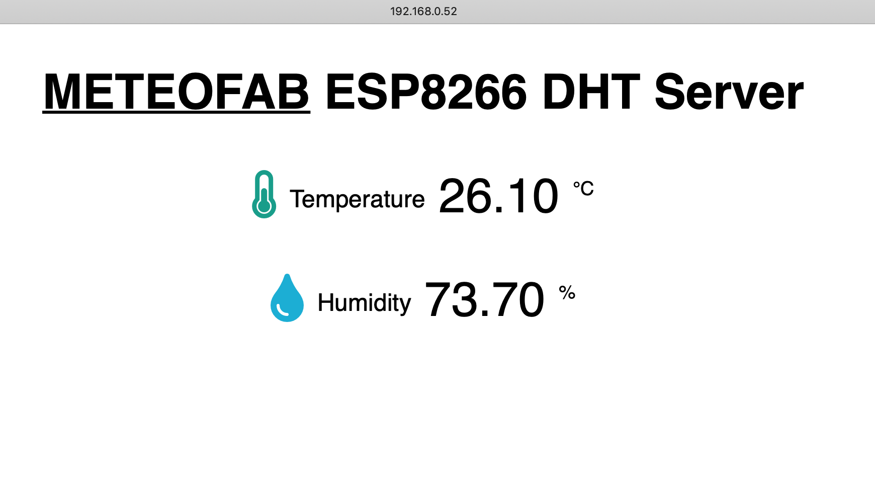
<h2><u>METEOFAB</u> ESP8266 DHT Server</h2>
<p>
<i class="fas fa-thermometer-half" style="color:#059e8a;"></i>
<span class="dht-labels">Temperature</span>
<span id="temperature">%TEMPERATURE%</span>
<sup class="units">°C</sup>
</p>
<p>
<i class="fas fa-tint" style="color:#00add6;"></i>
<span class="dht-labels">Humidity</span>
<span id="humidity">%HUMIDITY%</span>
<sup class="units">%</sup>
</p>
</body>
<script>
setInterval(function ( ) {
var xhttp = new XMLHttpRequest();
xhttp.onreadystatechange = function() {
if (this.readyState == 4 && this.status == 200) {
document.getElementById("temperature").innerHTML = this.responseText;
}
};
xhttp.open("GET", "/temperature", true);
xhttp.send();
}, 2000 ) ;
setInterval(function ( ) {
var xhttp = new XMLHttpRequest();
xhttp.onreadystatechange = function() {
if (this.readyState == 4 && this.status == 200) {
document.getElementById("humidity").innerHTML = this.responseText;
}
};
xhttp.open("GET", "/humidity", true);
xhttp.send();
}, 2000 ) ;
</script>
</html>)rawliteral";
// Replaces placeholder with DHT values
String processor(const String& var){
//Serial.println(var);
if(var == "TEMPERATURE"){
return String(t);
}
else if(var == "HUMIDITY"){
return String(h);
}
return String();
}
void setup(){
// Serial port for debugging purposes
Serial.begin(115200);
dht.begin();
// Connect to Wi-Fi
WiFi.begin(ssid, password);
Serial.println("Connecting to WiFi");
while (WiFi.status() != WL_CONNECTED) {
delay(1000);
Serial.println(".");
}
// Print ESP8266 Local IP Address
Serial.println(WiFi.localIP());
// Route for root / web page
server.on("/", HTTP_GET, [](AsyncWebServerRequest *request){
request->send_P(200, "text/html", index_html, processor);
});
server.on("/temperature", HTTP_GET, [](AsyncWebServerRequest *request){
request->send_P(200, "text/plain", String(t).c_str());
});
server.on("/humidity", HTTP_GET, [](AsyncWebServerRequest *request){
request->send_P(200, "text/plain", String(h).c_str());
});
// Start server
server.begin();
}
void loop(){
unsigned long currentMillis = millis();
if (currentMillis - previousMillis >= interval) {
// save the last time you updated the DHT values
previousMillis = currentMillis;
// Read temperature as Celsius (the default)
float newT = dht.readTemperature();
// Read temperature as Fahrenheit (isFahrenheit = true)
//float newT = dht.readTemperature(true);
// if temperature read failed, don't change t value
if (isnan(newT)) {
Serial.println("Failed to read from DHT sensor!");
}
else {
t = newT;
Serial.println(t);
}
// Read Humidity
float newH = dht.readHumidity();
// if humidity read failed, don't change h value
if (isnan(newH)) {
Serial.println("Failed to read from DHT sensor!");
}
else {
h = newH;
Serial.println(h);
}
}
}
These are the readings on the monitor: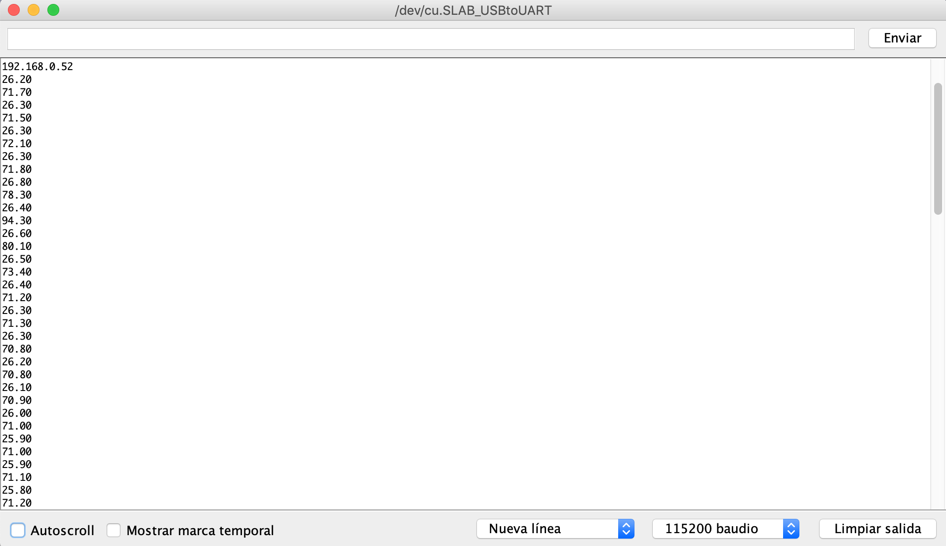
Copying the server IP address from the monitor, and pasting it on the browser's URL bar I got the webserver's display:
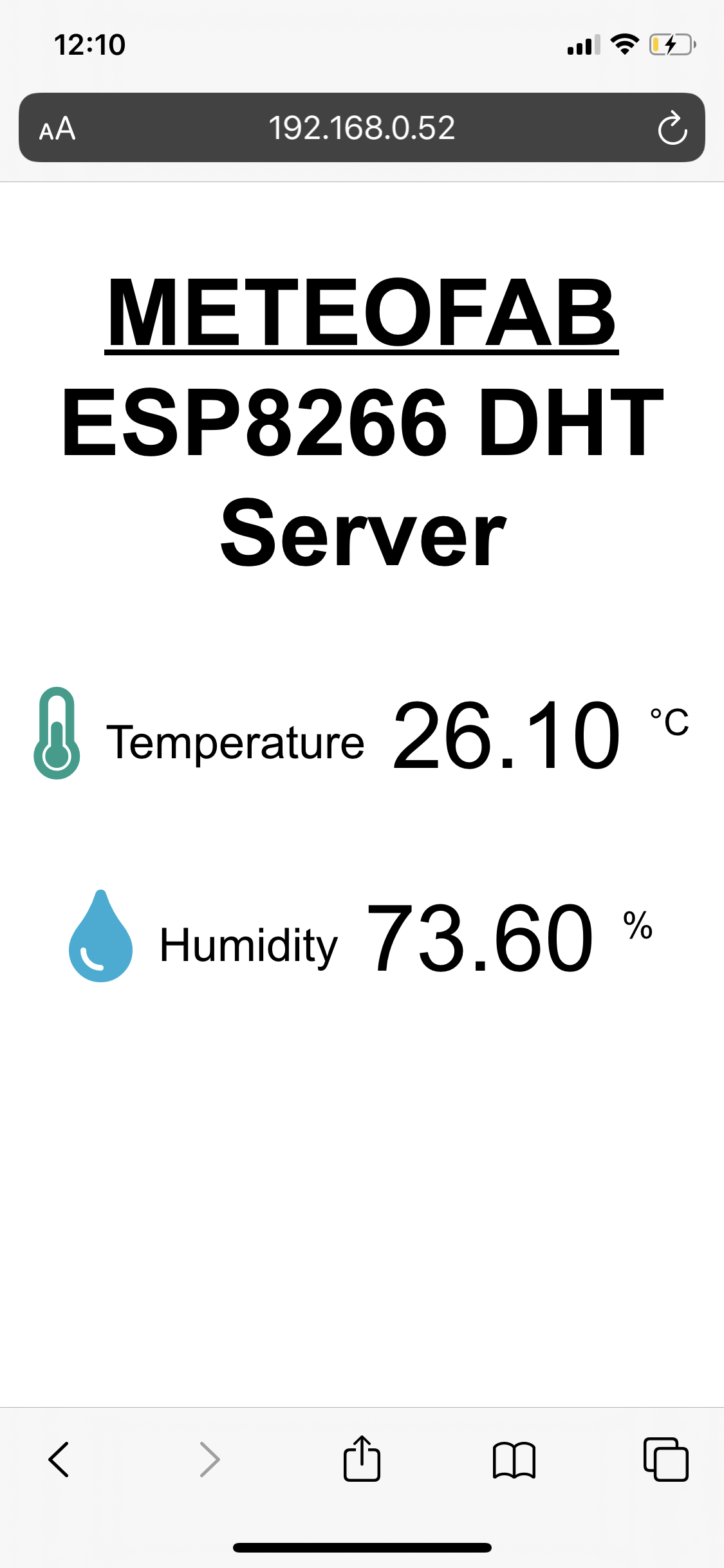
Then I tried entering from other devices connected to the wifi network as my phone:
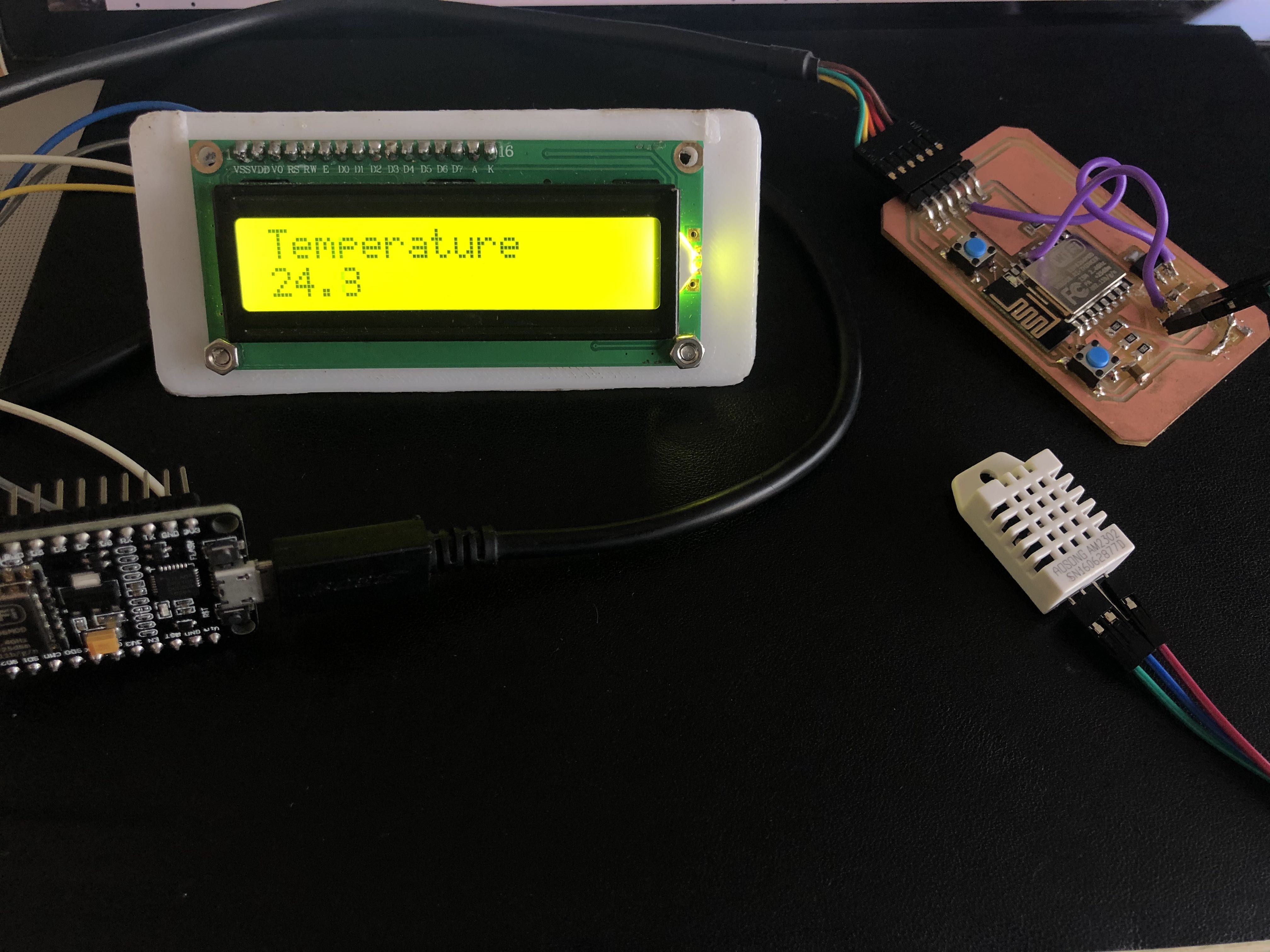
14.3.4. WiFi communication between two ESP8266 + LCD display
For this final part on the WiFi communication, I'm sending data between two ESP8266 modules: one, my WiFi module that gets the temperature data from the DHT22 sensor (Server) and a NodeMCU board (client) connected to a LCD display (with I2C scanner as on the previous 14.2 section).
I also followed the steps on this link. There are two different codes, one for the server which gets the data, creates the server with the info and goes to sleep till other device asks for that info to save power, and other for the client that grabs the data and outputs it through the LCD screen I mentioned.
On the server's code I must include the DHT and ESP libraries. I set the same data pin to read the sensor. This is the Server's code:
#include "DHT.h"                    // DHT22
#include <SPI.h>                    // SD
#include <Wire.h>                   // I2C->LCD
#include <ESP8266WiFi.h>

#define DHTPIN 5
#define DHTTYPE DHT22

WiFiServer server(80);              // launches the server
IPAddress ip(192, 168, 0, 80);      // fix IP of the server
IPAddress gateway(192,168,0,1);     // WiFi router's IP
IPAddress subnet(255,255,255,0);
DHT dht(DHTPIN, DHTTYPE);

char ssid[] = "********";
char pass[] = "********";
byte xc = 1, yc = 23, dx = 1, dy = 1;
unsigned long DHTtimer = 0;
float h, t;
unsigned long clientTimer = 0;

void setup() {
  Serial.begin(115200);                     // only for debug
  dht.begin();
  Wire.begin();                               // default SDA and SCL
  server_start(0);                            // starts the WiFi server
  delay(2000);
}

void loop() {
  if (millis() > DHTtimer + 2000) {
    h = dht.readHumidity();
    t = dht.readTemperature();
    Serial.println(t);
    Serial.println(h);// reads the DHT for temperature
    if (isnan(h) || isnan(t)) {
      return;
    } else {
      DHTtimer = millis();
    }

  }
  WiFiClient client = server.available();
  if (client) {
    if (client.connected()) {
      String request = client.readStringUntil('\r');    // reads the message from the client
      client.flush();
      client.println(String(t, 1));

    }
    client.stop();                         // disconnects the client
    clientTimer = millis();
  }
  if (millis() - clientTimer > 30000) {    // stops and restarts the WiFi server after 30 sec
    WiFi.disconnect();                     // idle time
    delay(500);
    server_start(1);
  }
}

void server_start(byte restart) {
  if (restart) {

  }
  WiFi.config(ip, gateway, subnet);
  WiFi.begin(ssid, pass);
  while (WiFi.status() != WL_CONNECTED) {
    delay(500);
  }
  server.begin();
  delay(500);
  clientTimer = millis();
}
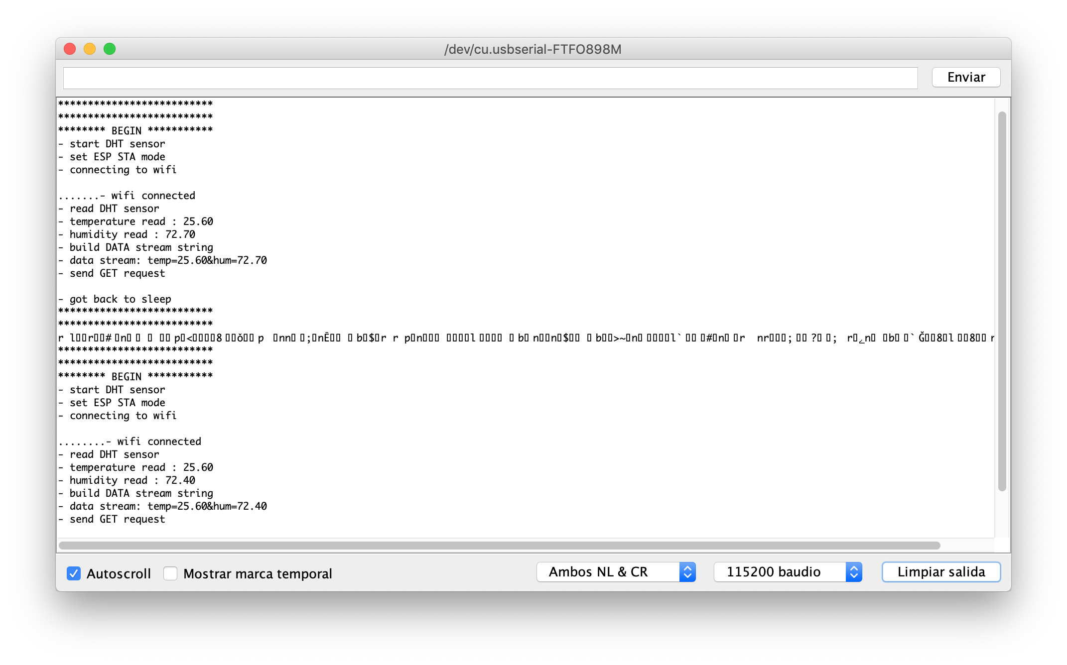
________________________________________________________________________This is the data shown on the monitor. Every time I press the reset button, the program will read the data, show it and go to sleep as shown below:
On the client's code I include the LCD and LCD-i2C libraries and set the same SSID and wifi password as before. Then I set the values for the i2c-LCD address and a readsStringUntil function as an answer to output on the display referring to the Server's data. This is the final Client's code:
#include <SPI.h>
#include <Wire.h>                   // I2C->LCD
#include <LiquidCrystal_I2C.h>
#include <ESP8266WiFi.h>

IPAddress server(192,168,0,80);     // fix IP of the server
WiFiClient client;

//LiquidCrystal_I2C lcd(0x27,16,2);
LiquidCrystal_I2C lcd(0x27, 2, 1, 0, 4, 5, 6, 7, 3, POSITIVE);

char ssid[] = "*********";
char pass[] = "*********";
byte xc = 1, yc = 23, dx = 1, dy = 1;
unsigned long askTimer = 0;
unsigned long oledTimer = 0;
String answer;
//uint8_t pinD1 = 5;    // I2C Bus SCL (clock)
//uint8_t pinD2 = 4;    // I2C Bus SDA (data)
//uint8_t pinD3 = 0;
//uint8_t pinD4 = 2;


void setup() {
  lcd.begin(16,2);
  Serial.begin(115200);

  WiFi.begin(ssid, pass);
  while (WiFi.status() != WL_CONNECTED) {
    delay(500);
  }
}

void loop () {
  if (millis() - askTimer > 2340) {         // time between two connection to the server
    client.connect(server, 80);             // connects to the server
    client.println("Haliho szerver!\r");    // trigger message to the server, its value is scrapped
    answer = client.readStringUntil('\r');  // received the server's answer
    Serial.println(answer);

    lcd.clear();
    lcd.setCursor(0,0);
    lcd.print("Temperature C");
    lcd.setCursor(0,1);
    lcd.print(answer);
    delay(2000);
//    lcd.clear;
//    lcd.setCursor(0,0);
//    lcd.print("Humidity %");
//    lcd.setCursor(0,1);
//    lcd.print(answer);


    client.flush();
    askTimer = millis();

  }
}
________________________________________________________________________On the following video, you can see the temperature read by the sensor connected to the wifi module and displayed on the arduino monitor and LCD display connected to the NodeMCU board on real time:
14.4. Bluetooth Low Energy communication (BLE) - (EXTRA - WIP)
For this assignment I also wanted to build a bluetooth shield to send the data readings by the sensors (temperature, humidity and wind/rain gauge) on my weather station device for the final project.
I am choosing bluetooth connection over a wifi network to simplify its system as the device is thought to be used in rural areas where internet access is not very common. Therefore, the data sending so far will be adapted for communications between devices with bluetooth connections only.
Material
First for designing my communication shield board I will be using the Bluetooth 4.2 Low Energy Module Shield HM-08 (which is the one on the Lab). I prefer to design the board from zero to create a new one which also includes the pin connections for the LCD Display (as an output shield board).
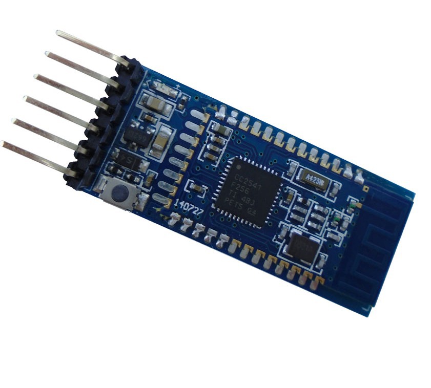
Another option was to use a Bluetooth SM-HC-08 module, and connect it directly to the board for testing the data sendings first.
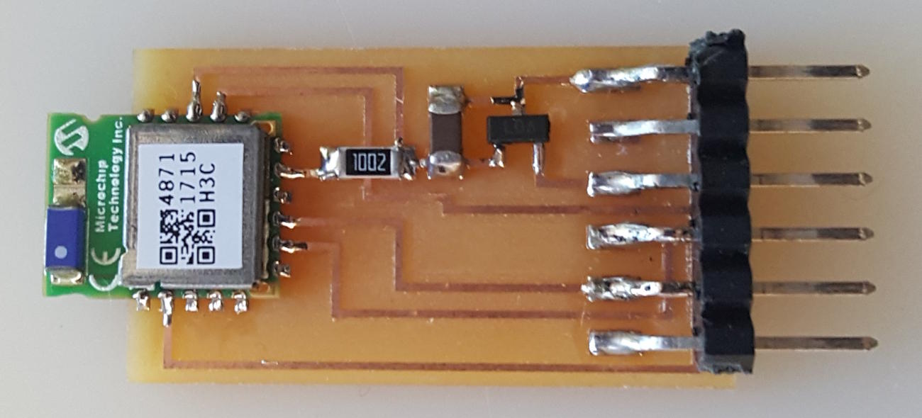
Board production
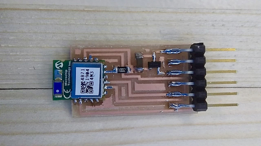
I am taking as a reference this Bluetooth module board called hello.RN4871.ftdi BLE board similar to this HM-11 Bluetooth module. The board should look like this:
This is the circuit's schematics:
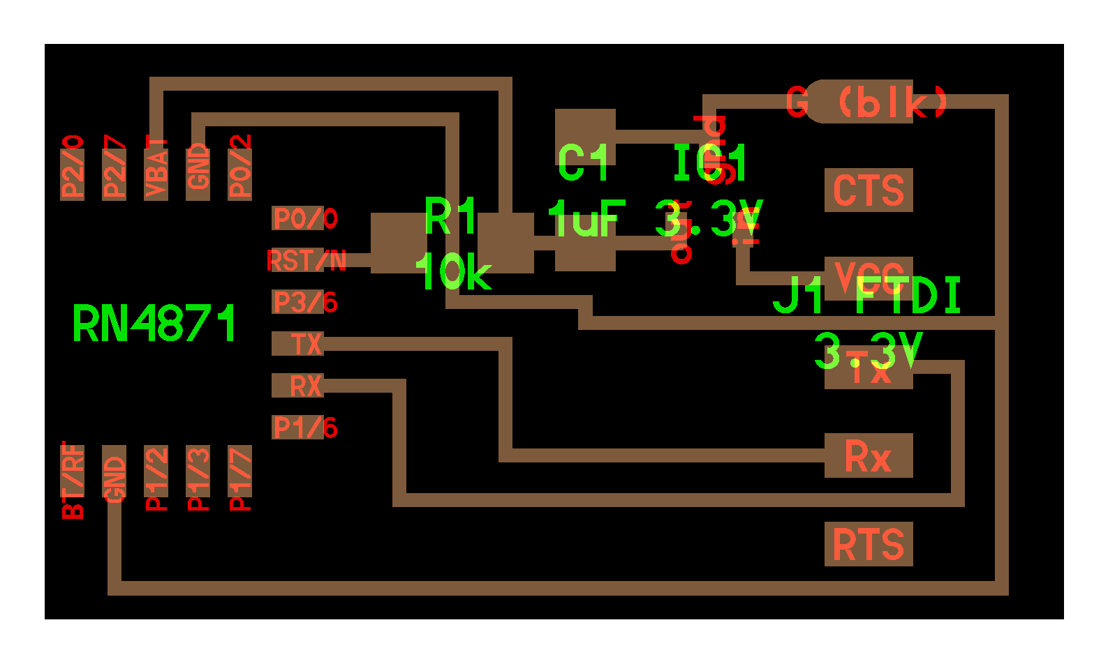
And these are the png files that I used to create the milling ones:

I milled one PCB that should include the next elements:
- Bluetooth BLE 4.2. RN4871-I/RM128 microchip
- 10 kohm resistor
- 5 to 3.3 voltage regulator
- 1 uF capacitor
- 6 pin serial FTDI connection
It was not a difficult to solder all the elements onto the board, so this is the final result:
Board programming
14.5. Download Files
Here there are the original design files