6.1. Basics of 3D printing
A bit of introduction
Here there are a couple of links to previous information about the topic shared by Fab Academy by its official Lesson about 3D printing and scanning and recitation course about functional representations.
6.1.1. 3D PRINTING PROCESSES
There are several different kind of 3D-printing machines in Fab Lab Barcelona. We mainly are using 4 of them, which differ in some aspects such as flexibility of using and setting, materials, nozzle dimension, speed of printing, size, etc. The four models are the following:
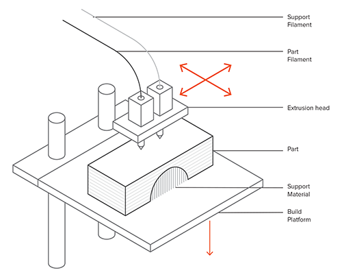
- Material Extrusion (FDM/FFF): Fused Deposition Modeling (FDM), or Fused Filament Fabrication (FFF), is an additive manufacturing process that belongs to the material extrusion family. In FDM, an object is built by selectively depositing melted material in a pre-determined path layer-by-layer. The materials used are thermoplastic polymers and come in a filament form.
FDM is the most widely used 3D Printing technology: it represents the largest installed base of 3D printers globally and is often the first technology people are exposed to. In this article, the basic principles and the key aspects of the technology are presented.
- Stereolithography (SLA): is an additive manufacturing process that belongs to the Vat Photopolymerization family. In SLA, an object is created by selectively curing a polymer resin layer-by-layer using an ultraviolet (UV) laser beam. The materials used in SLA are photosensitive thermoset polymers that come in a liquid form.
SLA is famous for being the first 3D Printing technology: its inventor patented the technology back in 1986. If parts of very high accuracy or smooth surface finish are needed, SLA is the most cost-effective 3D printing technology available. Best results are achieved when the designer takes advantage of the benefits and limitations of the manufacturing process.

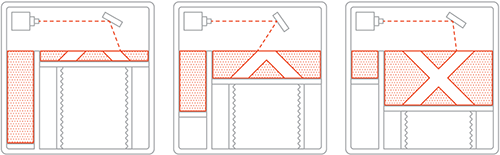
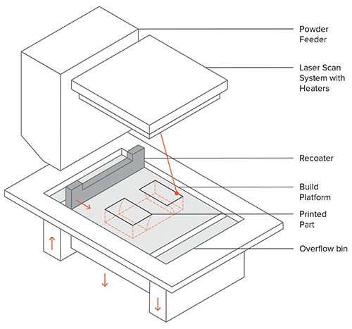
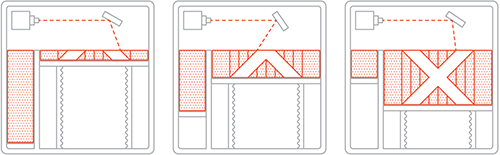
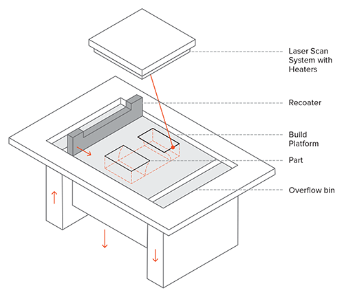
- Selective Laser Sintering (SLS): is an Additive Manufacturing process that belongs to the Powder Bed Fusion family. In SLS, a laser selectively sinters the particles of a polymer powder, fusing them together and building a part layer-by-layer. The materials used in SLS are thermoplastic polymers that come in a granular form.
SLS 3D Printing is used for both prototyping of functional polymer components and for small production runs, as it offers a very high design freedom, high accuracy and produces parts with good and consistent mechanical properties, unlike FDM or SLA. The capabilities of the technology can be used to its fullest though, only when the designer takes into consideration its key benefits and limitations.
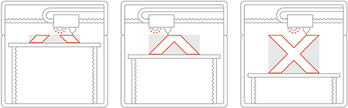
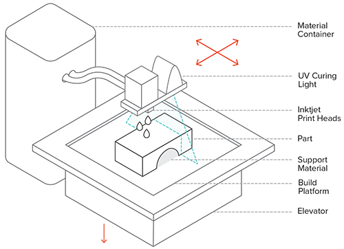
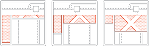
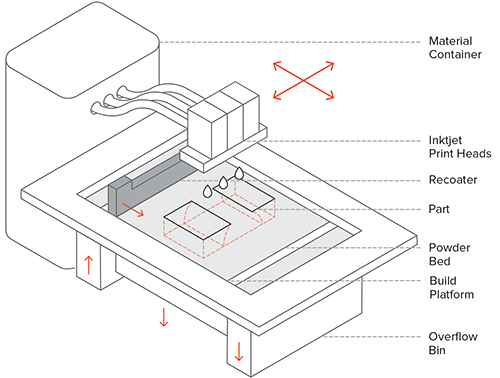
- Material Jetting (MJ): is an additive manufacturing process that operates in a similar fashion to 2D printers. In material jetting, a printhead (similar to the printheads used for standard inkjet printing) dispenses droplets of a photosensitive material that solidifies under ultraviolet (UV) light, building a part layer-by-layer. The materials used in MJ are thermoset photopolymers (acrylics) that come in a liquid form.
MJ 3D Printing creates parts of high dimensional accuracy with a very smooth surface finish. Multi-material printing and a wide range of materials (such as ABS-like, rubber-like and fully transparent materials) are available in Material Jetting. These characteristics make MJ a very attractive option for both visual prototypes and tooling manufacturing. Nevertheless, material jetting has some key limitations that we present in this article.
- Binder Jetting (BJ): is a family of additive manufacturing processes. In Binder Jetting, a binder is selectively deposited onto the powder bed, bonding these areas together to form a solid part one layer at a time. The materials commonly used in Binder Jetting are metals, sand, and ceramics that come in a granular form.
Binder Jetting is used in various applications, including the fabrication of full-color prototypes (such as figurines), the production of large sand casting cores and molds and the manufacture of low-cost 3D printed metal parts.
- Powder Bed Fusion (metals) (BJ): Selective Laser Melting (SLM) and Direct Metal Laser Sintering (DMLS) are two metal additive manufacturing processes that belong to the powder bed fusion 3D printing family. The two technologies have a lot of similarities: both use a laser to scan and selectively fuse (or melt) the metal powder particles, bonding them together and building a part layer-by-layer. Also, the materials used in both processes are metals that come in a granular form.
The differences between SLM and DMLS come down to the fundamentals of the particle bonding process (and also patents): SLM uses metal powders with a single melting temperature and fully melts the particles, while in DMLS the powder is composed of materials with variable melting points that fuse on a molecular level at elevated temperatures.
6.1.2. 3D printing Materials
I will focus on materials used in extrusion processes. On this table we can observe the difference between materials in terms of their physical and process properties:
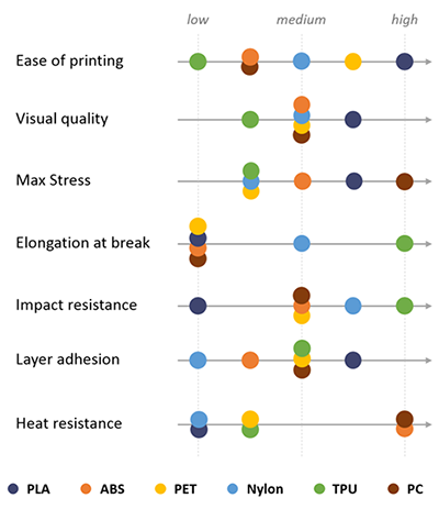
- PLA is the easiest polymer to print and provides good visual quality. It is very rigid and actually quite strong, but is very brittle.
- ABS is usually picked over PLA when higher temperature resistance and higher toughness is required.
- PET is a slightly softer polymer that is well rounded and possesses interesting additional properties with few major drawbacks.
- Nylon possesses great mechanical properties, and in particular, the best impact resistance for a non-flexible filament. Layer adhesion can be an issue, however.
6.1.3. 3D printing Machines
There are several different kind of 3D-printing machines in Fab Lab Barcelona:
We mainly are using 4 of them, which differ in some aspects such as flexibility of using and setting, materials, nozzle dimension, speed of printing, size, etc. The four models are the following:


1. Ultimaker2
2. Anycubic
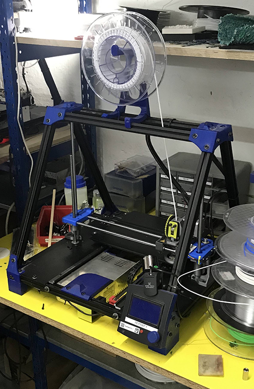
3. RepRap1
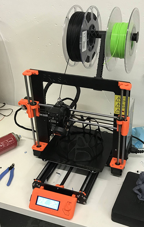
4. Prusa i3 MK3
6.1.4. Some useful tools
There are some useful tools to use while 3d printing process:
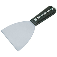
- Putty knife is used to remove carefully the piece from the bed of the printer.
- Hairspray is used to cover the working bed, in case it's made of glass or any slippy surface, so that the piece can be easily attached to the ground without leaving any trace of material on it. In case the bed is covered with teflon, the hairspray won't be necessary.
- Post-processing coating
6.1.5. Software
The software needed for the assignmet is divided between:
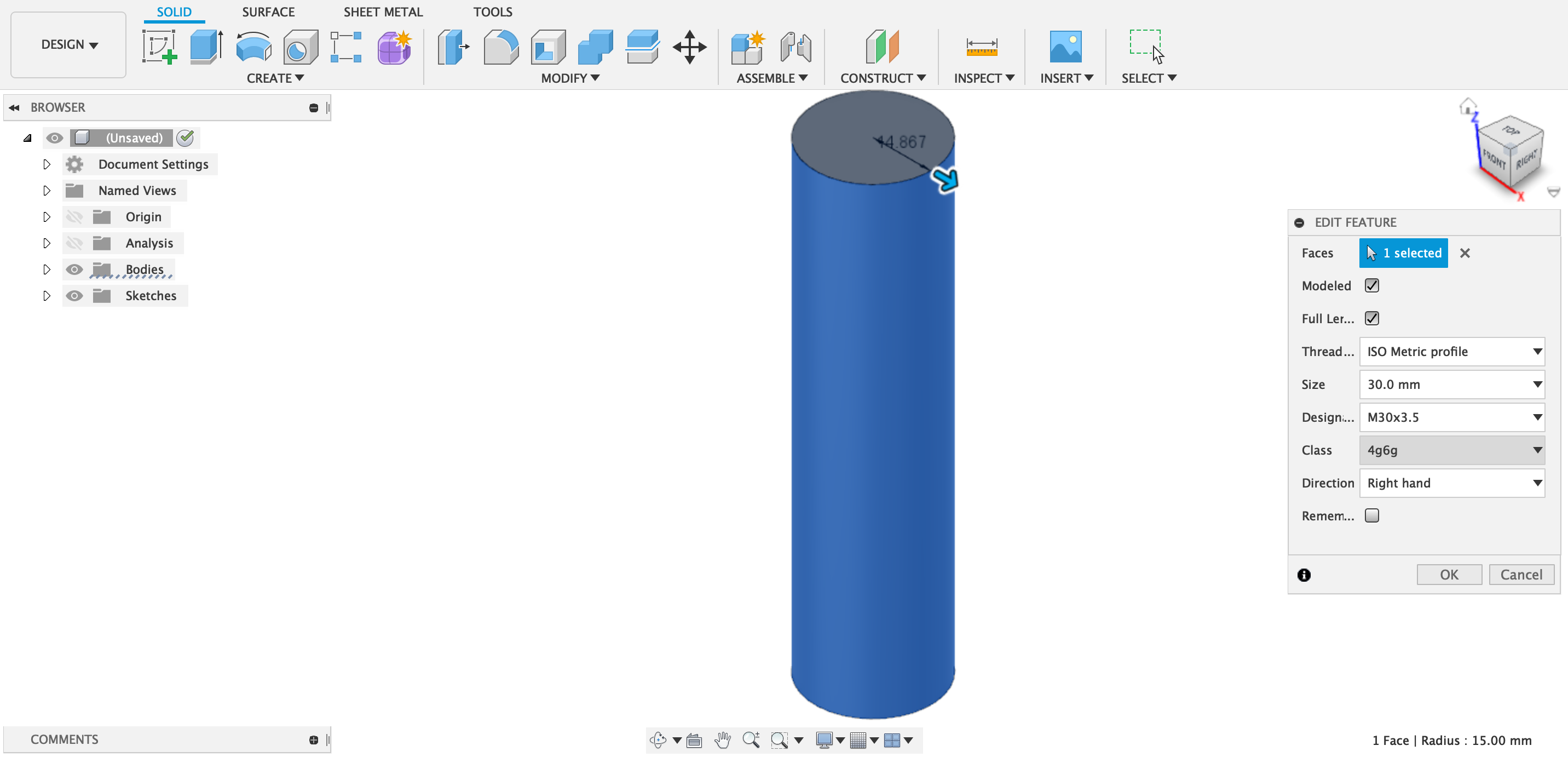
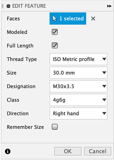
- Modelling and .stl files creating softwares: Fusion360, Solidworks, Creo Parametric, Rhinoceros, etc. This software is used to model the design and export it into .stl format, which mainly turns the whole model into a complex mesh of triangled geometry to be read by the printing machine software. The mesh configuration sets the finishing quality and geometrical complexity of the piece.
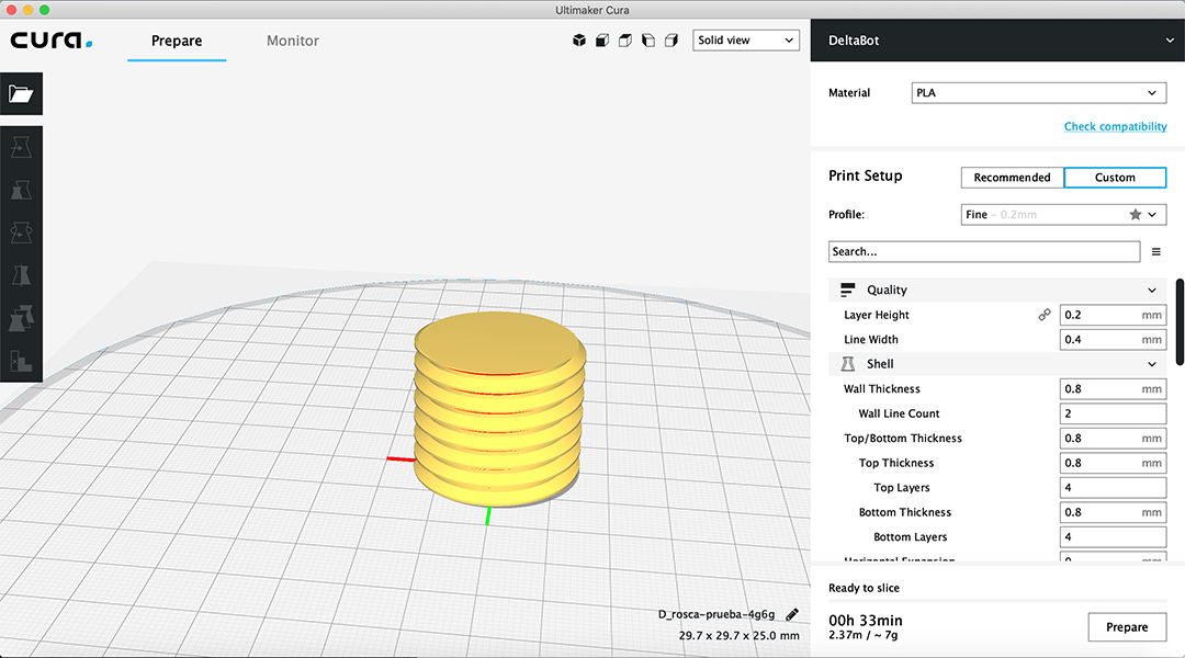
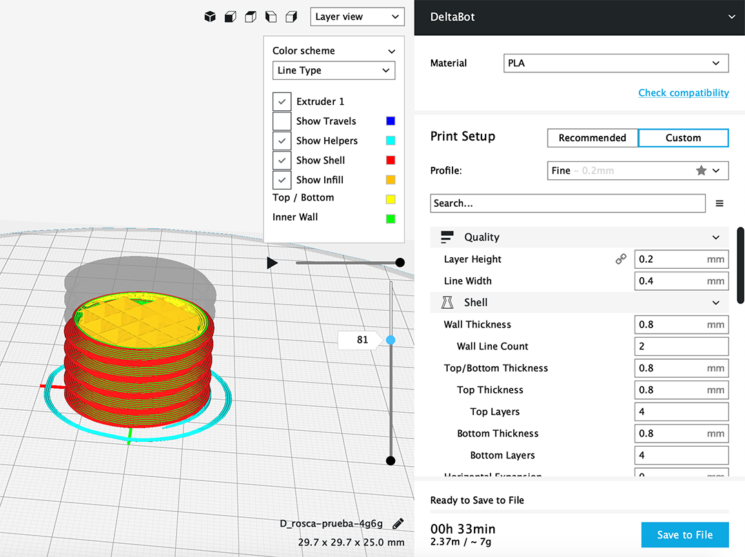
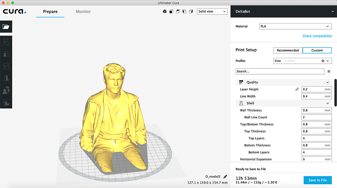
- 3d printing machine software: Cura, Prusa, Slic3r Prusa, etc. This software will set all the material, printer and process settings in terms of filament density, printer temperature, printing speed, infill structure, and many others that will be explained later.
6.2. Group Assignment
Autors: Josep Marti, Felipe Santos, Diar Amin, Gustavo Abreu and Alberto Martinez.
6.2.1. Testing printers:
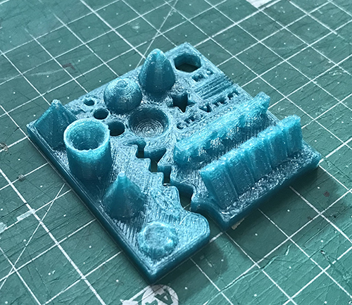
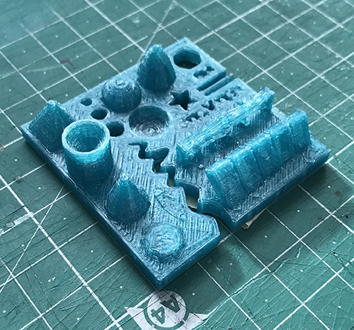
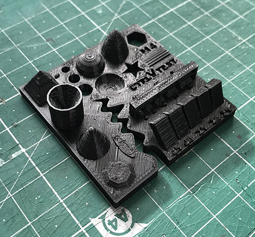
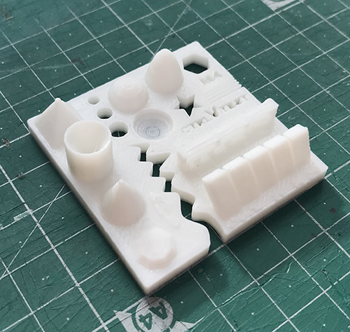
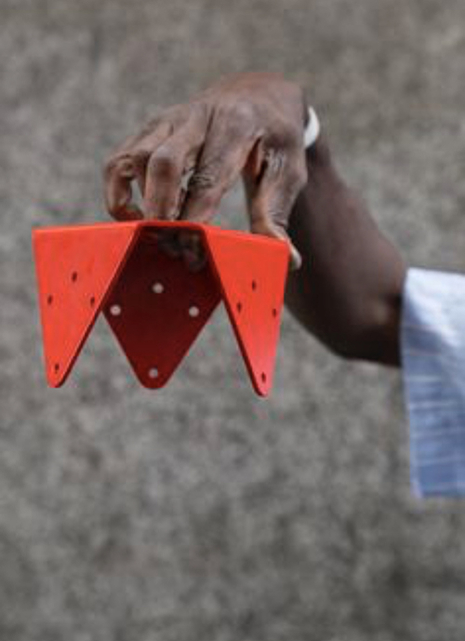
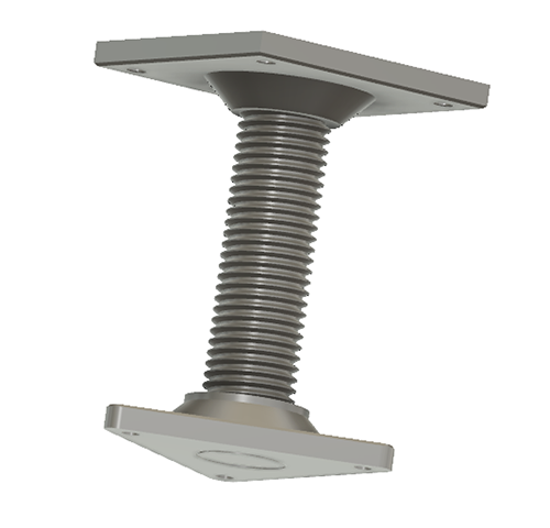
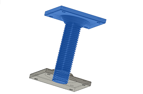
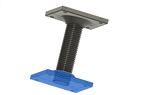
To test the different printers, the best option is to print a part that shows how the printer behaves in different situations. To do this, we’ve used a file available on thingiverse.
This article explains what should be measured as pointed below:
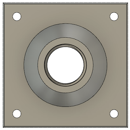
- Size: the object is 4 x 50 x 50 mm (baseplate) — measure with a caliper
- Hole size: 3 holes (3/4/5mm) — measure with a caliper/drill
- Nut size: M4 nut should fit perfectly — insert an M4 nut; it should need a little pressure
- Rounded print: wave, half sphere — check if all things look nice and smooth
- Minimum distance between walls: 0.1/0.2/0.3/0.4/0.5 mm — depending on your nozzle size and slicer settings you will get different results
- Overhang: 25°/30°/35°/40°/45° — depending on printed material/cooling, these will not be as seen on the rendering provided
We've used the same slicing parameters on every machine to have somewhat similar results. Although we could not use the same filament since the diameters were different.
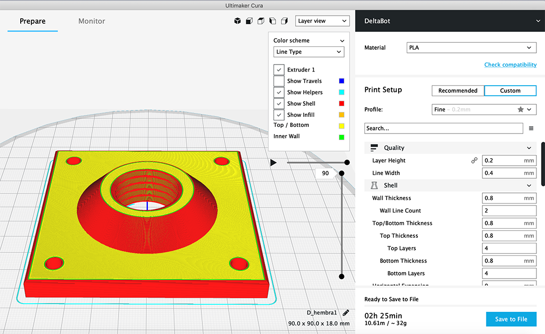
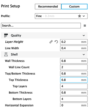
6.2.2. Slicing settings:
Layer height: 0.2mm
Wall line count: 2
Top layers: 6
Bottom layers: 4
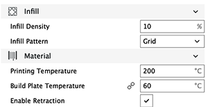
Infill: 20%
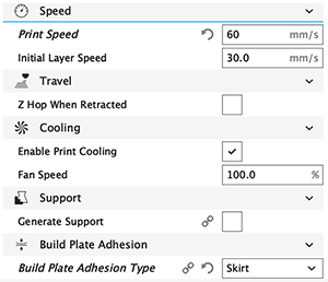
Speed: 60mm/s
Nozzle temp.: 205
Bed temp.: 60
Material: PLA
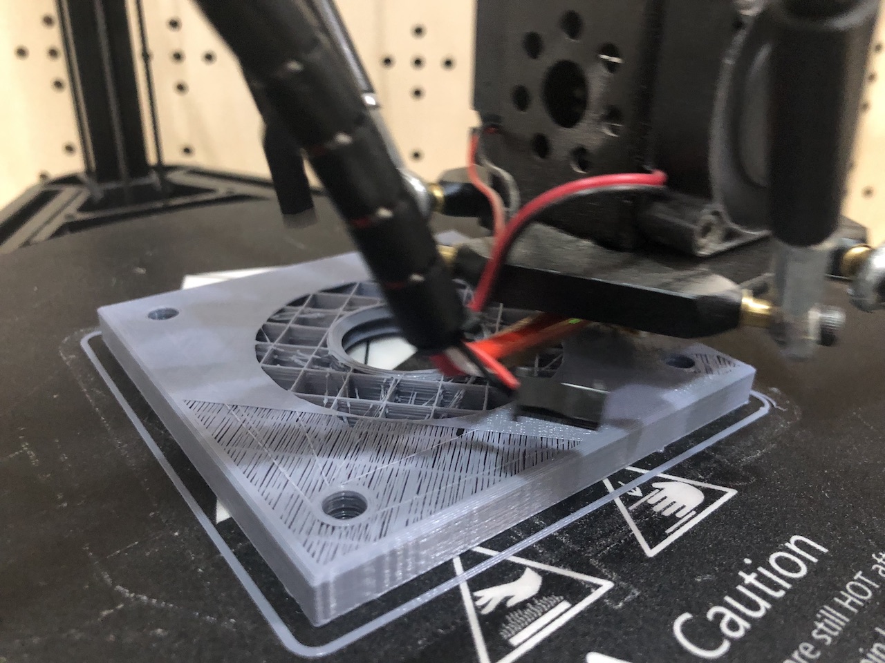
6.2.3. Printing process
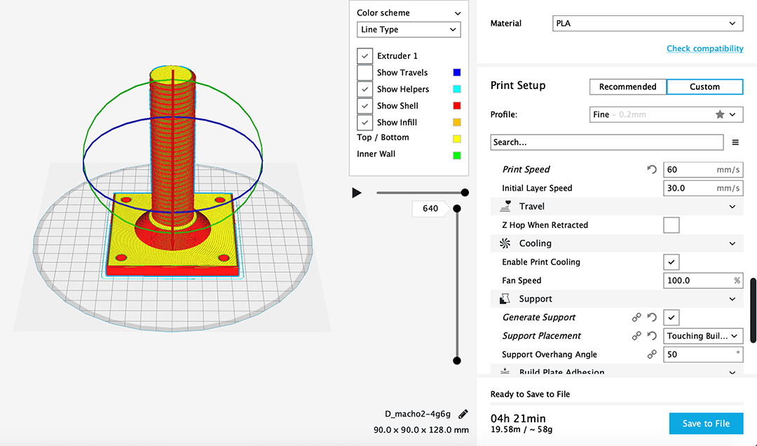
For the printing process, we will need to import the .stl file with the proper software, Cura (for Ultimaker2, RepRap and Anycubic) or Slic3r for Prusa (for Prusa i3 MK3).
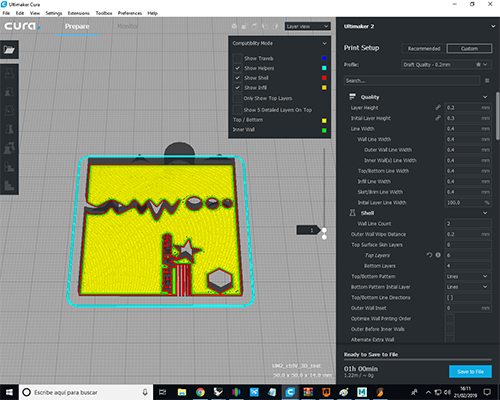
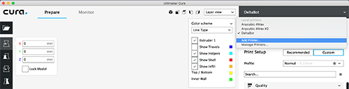
For Slic3 Prusa software, there won't be necessary to change the printers settings, but for the Cura, in case we want to change the printer model we should make the following changes:
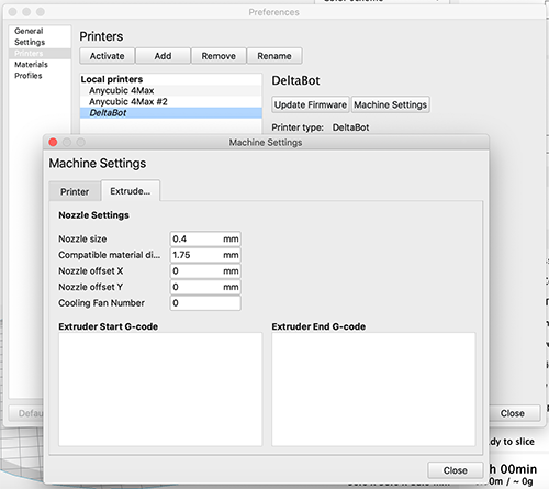
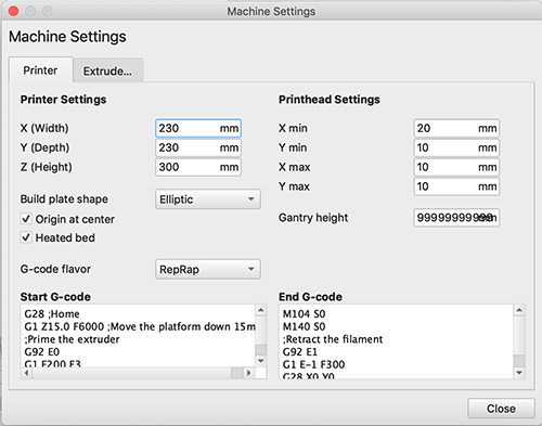
Then, the necessary parameters should be set on the configuration:
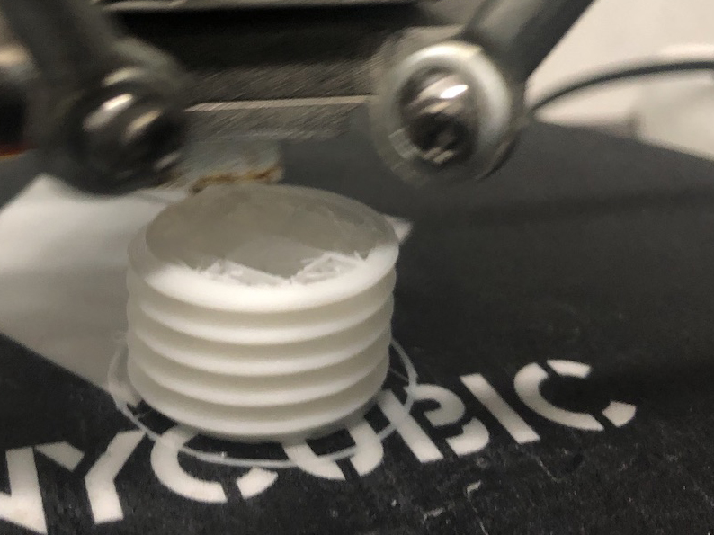
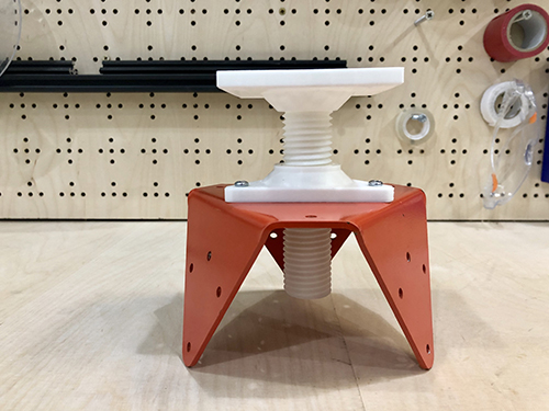
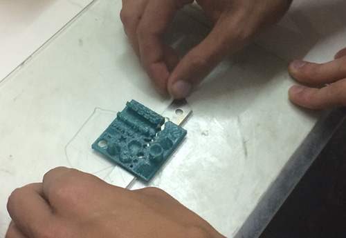
Once the print is done, we can remove the model from the workin bed carefully with a putty-knife or a blade.
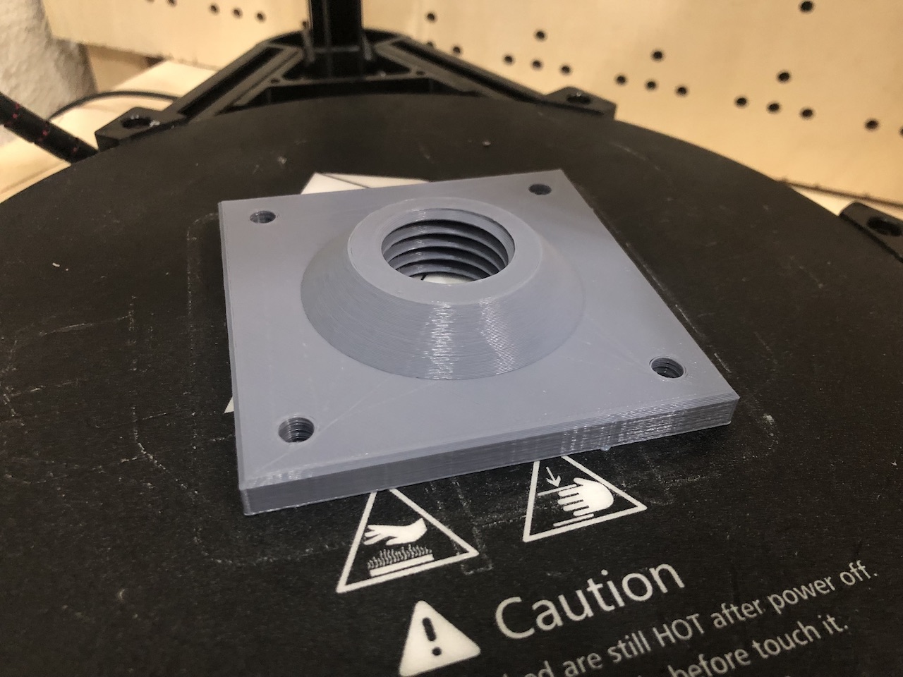
6.2.4. Testing results
These are the results of the testings: