4 - Electronics Production
Group Assignment
Participants
Josep Marti, Felipe Santos, Alberto Lopez, Diar Amin, Gustavo Abreu, Eva Blsakova and Juan Carlos Rincón.
Machines
Fab Lab barcelona have two different Roland milling machines:
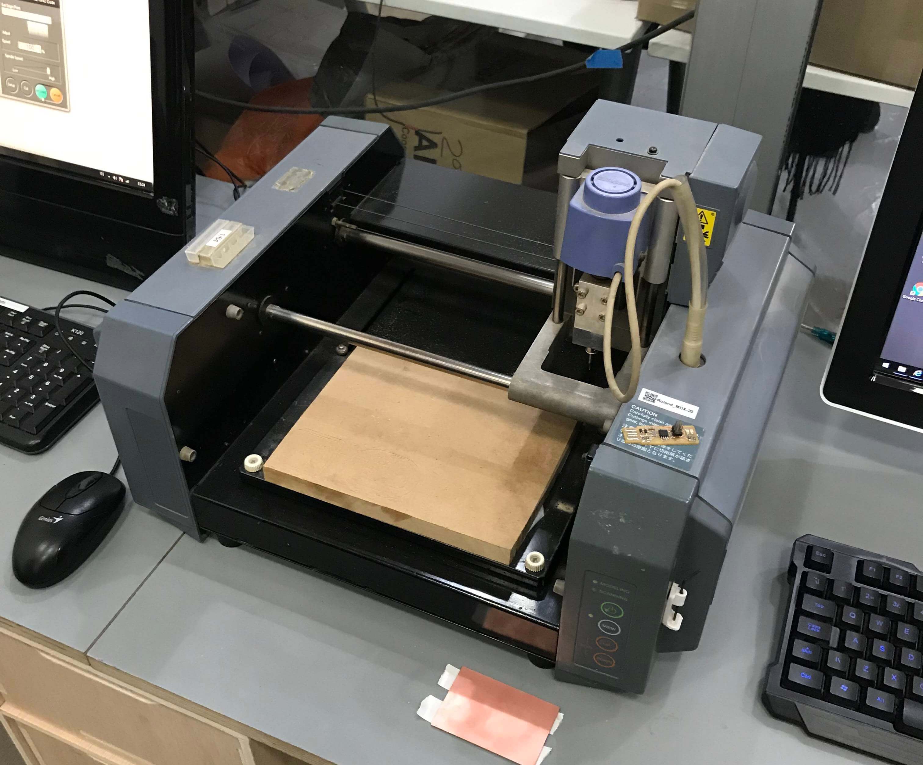
The Roland Modela MDX-20 is a small milling machine and a 2 1/2D precision scanner. This machine is mostly used for milling circuit boards, though it can also mill in other soft materials like machinable wax. For milling circuit boards you should export your design into a black&white monochrome png. For milling out 3 dimensional molds you should export your design as .stl The second use of this machine is scanning. It uses a thin needle to gently touch the object and calculates from this a 2 and a half dimensional model. Though slow at processing, it can create a highly detailed model. Work area: 203 x 152 x 60 mm From wikipedia.
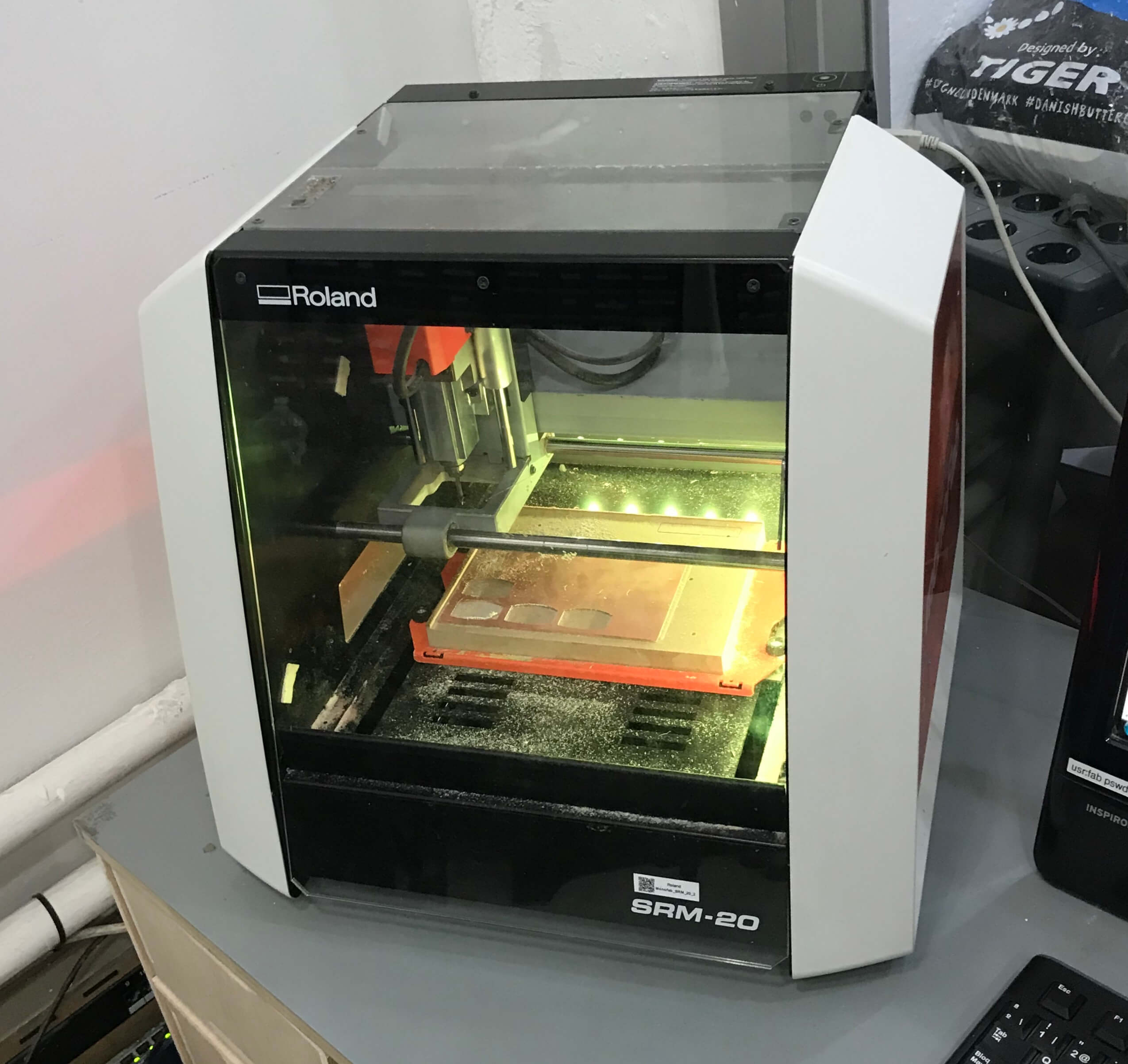
The SRM-20 is capable of cutting a wide variety of materials, including chemical wood, acrylic, and ABS. It is also capable of a range of accuracy settings from prototype to product design. Plus its small size and fully covered design allows you to enjoy cutting more safely and with peace of mind. Work area: 203 x 152 x 71 mm from User Manual.
Milling bits
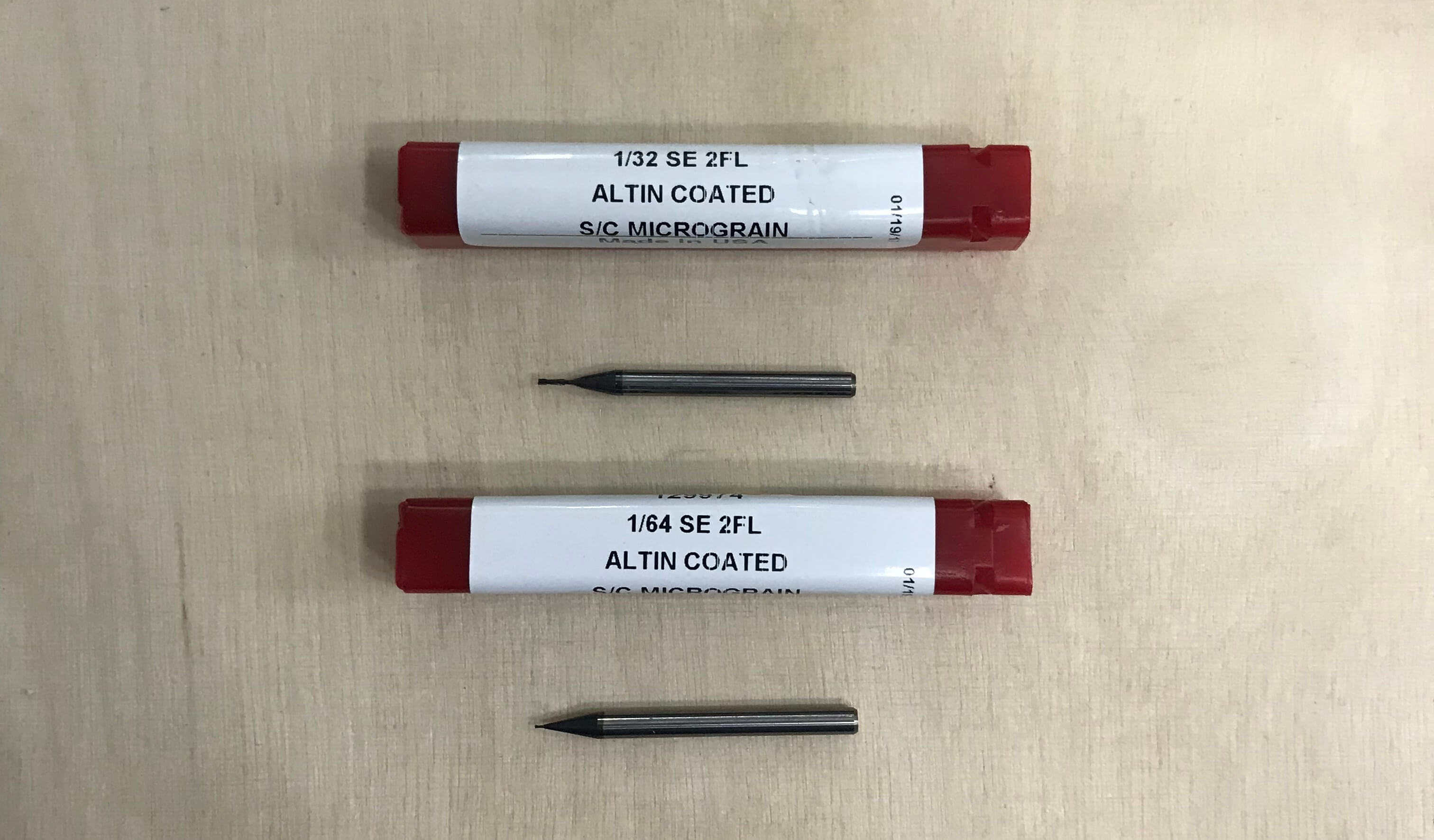
We have two different bits to work with our PCBs.
1/64" - Used for milling the trails on the board.
1/32" - Used for drilling holes and cutting the board.
Softwares
Our instructors recommended us to test the machines generating files from two different softwares: MODS and Fab Modules.
Mods
Right click program, open server program,machines, roland, mill, srm-20, PCB.
Steps followed:
- Load png file
- Select trace or cut
- Change settings for the machine to origin 0,0,0 and home 0,0,5 (x,y,z)
- Delete the WebSocket module
- Add the save module instead
- Calculate path
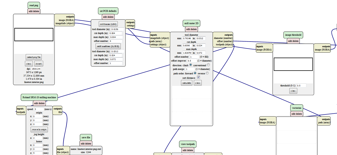
Fab Modules
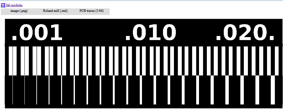
Download the line test document linetest.png.
Open the Fabmodules: http://fabmodules.org/.
Click fab modules, than index.html and open the format png-document. Select Roland mill and PCB traces.
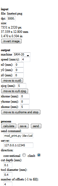
Insert settings:
Now we do the same procedure with the outline cut. Dropping the “linetestinginterior.png” file into the Fab Modules. Same machine (Roland Mill) and different cutting (PCB Outline 1/32).
Process Description
Choose the correct mill bit for the job and insert it into the machine. Than adjust the z-axis “by hand”.
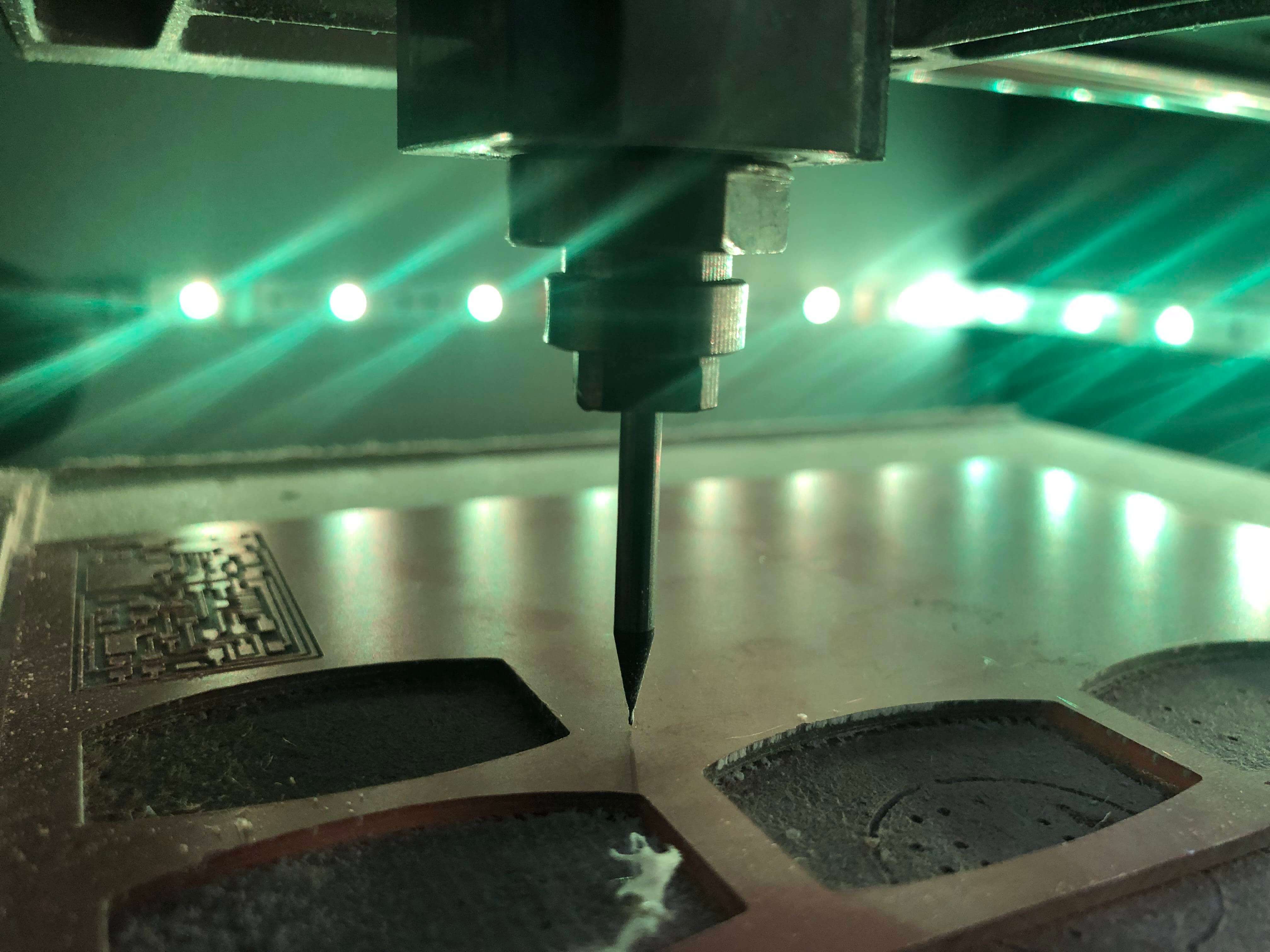
After that, set origin point for X and Y axis.
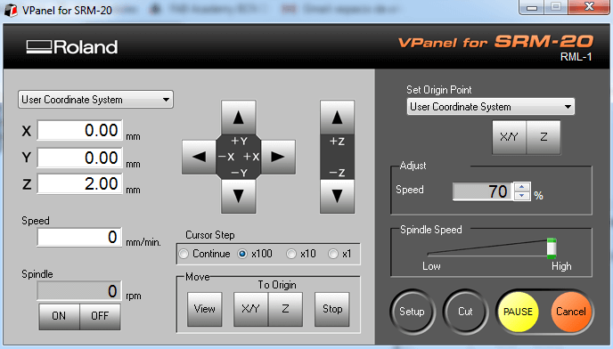
Then press “cut” to get to add the file “linetest.rml” and the job will start.
Check if the milling goes well, not too deep, not cutting air.
After finishing, just press view and it will bring the piece forward.
Then we get the milled piece.
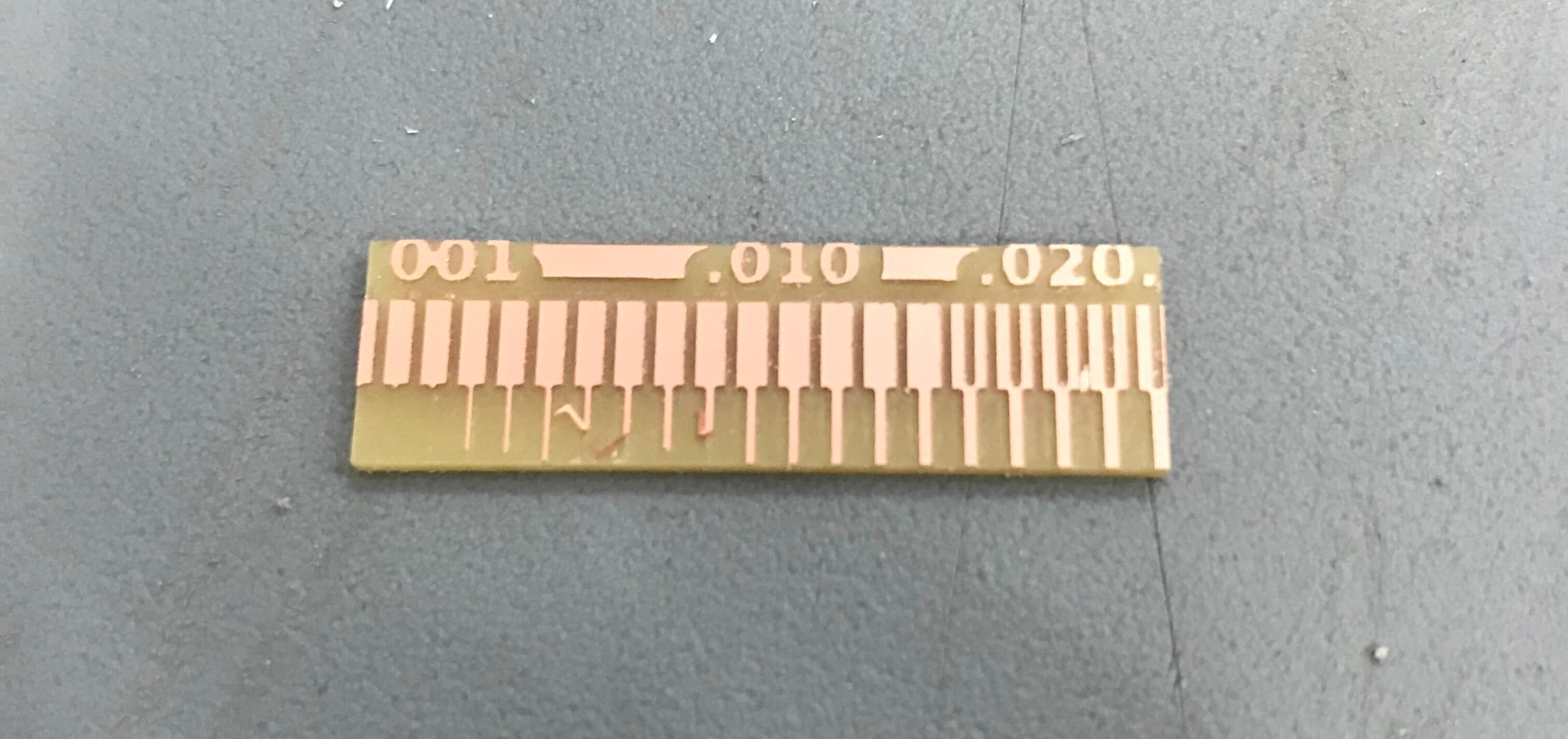
Compare the results
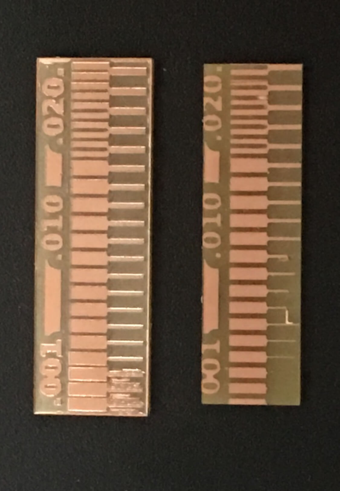
Conclusion
Using the same machine, bits and board; MODS presented better results. Begin able to mill up to .005 lines when fab modules only could do .011. So our software of choice for the rest of the process will be MODS.
Individual Assignment
After having tested the machines and learning how to use them, we had to mill our own programmer board. To do so, we could follow some of the models presented by Neil. I chose the basic hello.IPS.44 because the other ones are prepared to connect directly to the USB port of the computer, but I was told that this can give problems because of the lack of thickness can give a bad connexion. The hello.IPS.44 is connected via a mini USB cable.
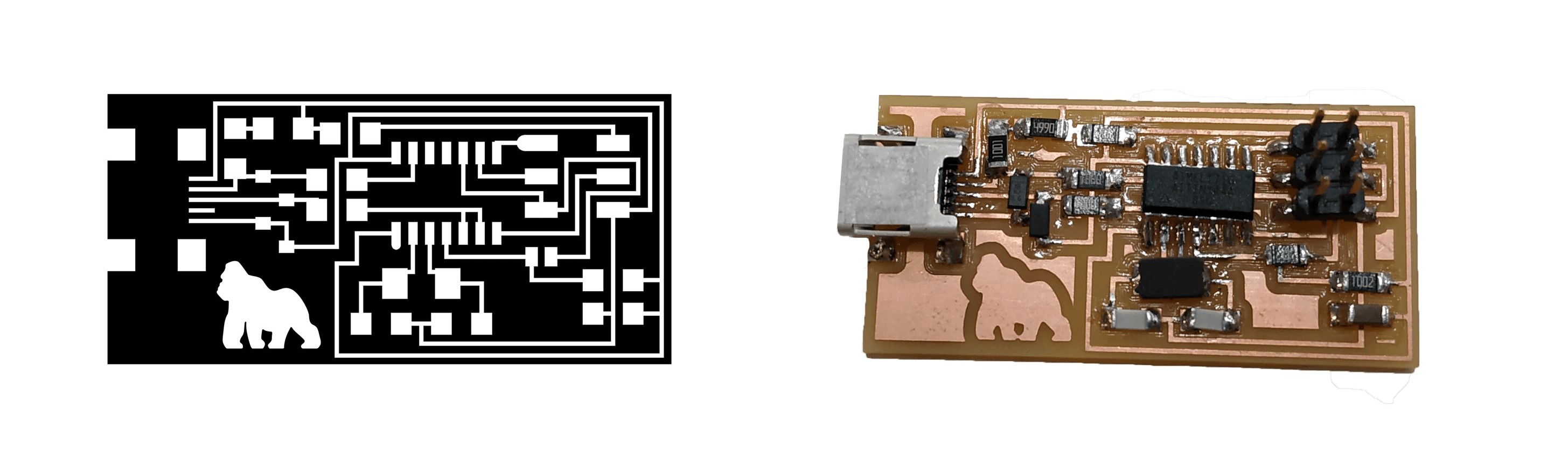
With the decision made, the next step was to mill it in the machine. I mill it with the Roland SRM-20 like the group assignment. I downloaded the .png files of the board from the general FabAcademy Week 04 assignment page. There are two files, the traces image defines the lines and connections and the interior are the borders to cut the final board.
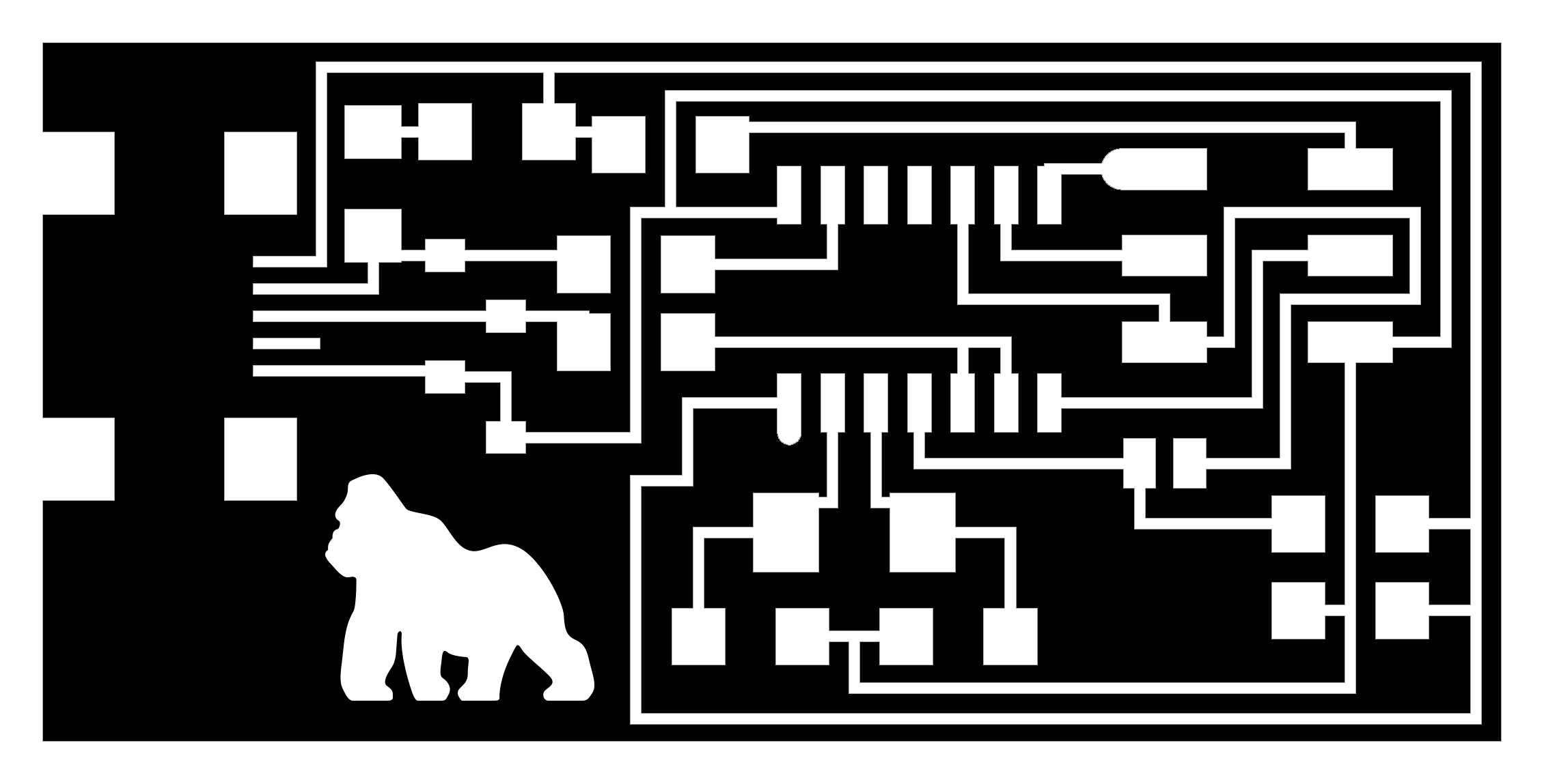
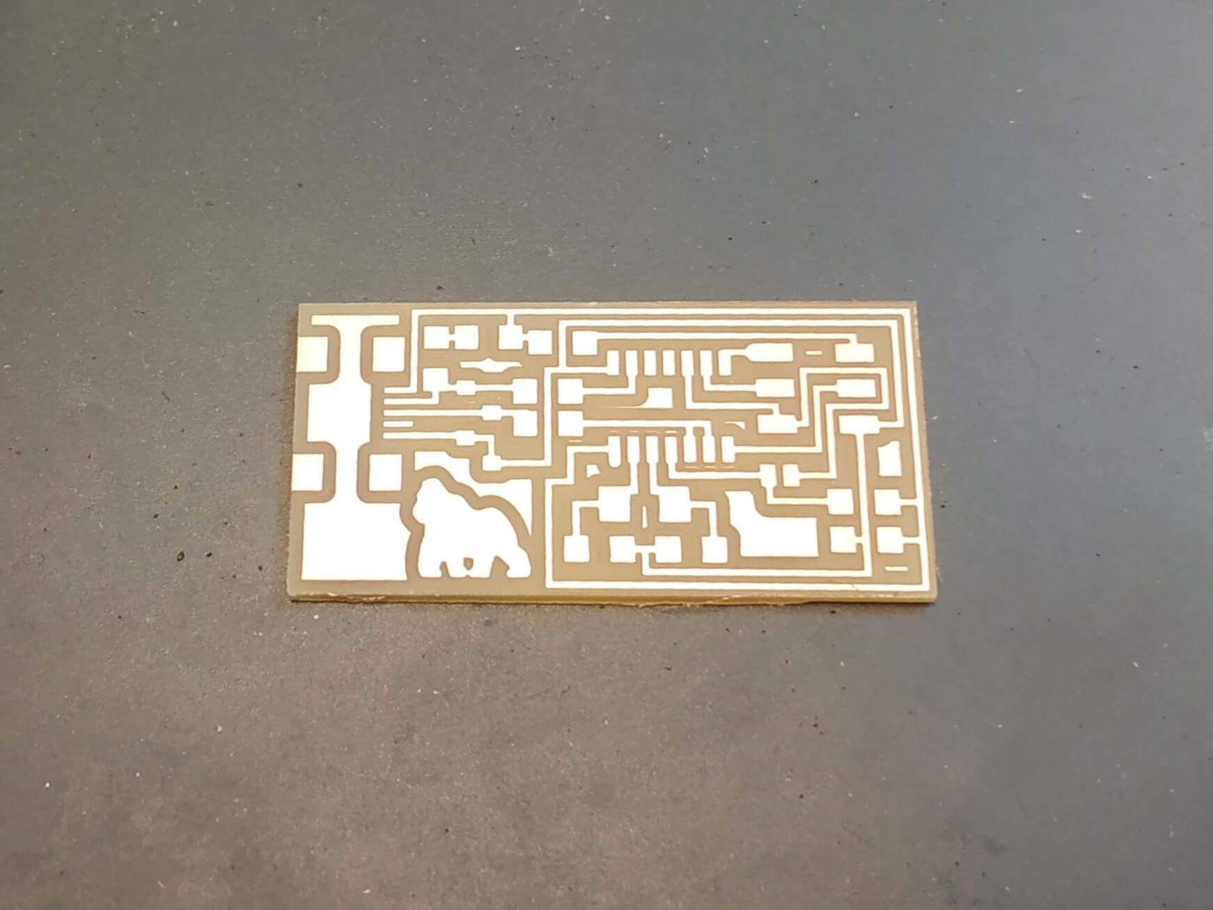
To customize it, I decided to do a different design with a gorilla on it. To do so, I used Adobe Photoshop to create the new design. I didn't change any connection, I only add the gorilla on it, but it doesn't affect the board. If you want to do it, make sure that you don't change the dimensions of the board, as the components have to fit to the existing paths.

CNC Milling Machine
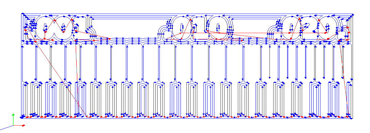
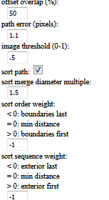
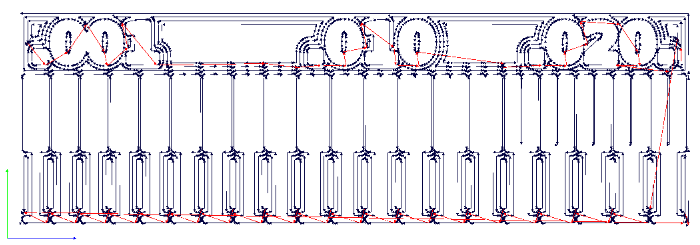
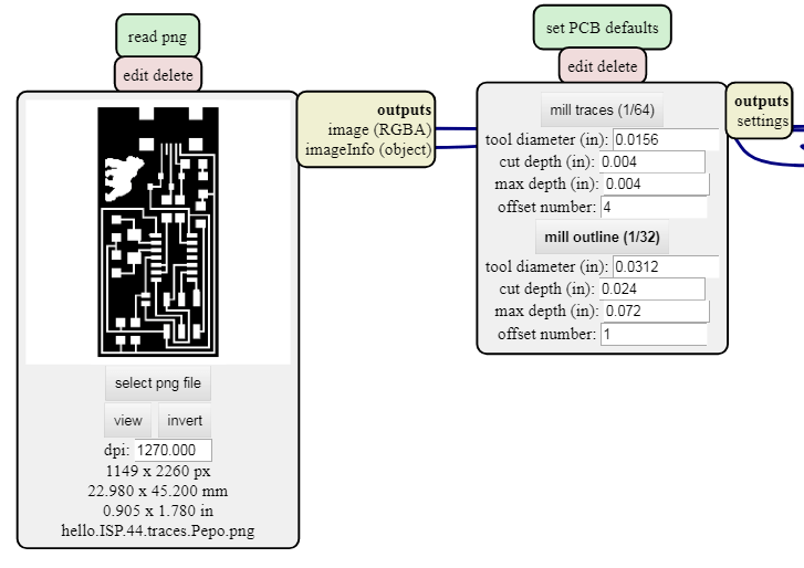
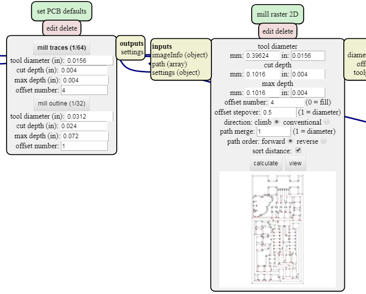
The next step is to create the .rml file with mods. We had the code prepared from the group assignment, but the idea is to open mods, and then open the program for our machine. With the model open, we can upload our design in a .png format. Then make sure to change the settings, we have to set the origin and the home positions. For the origin always put the 0,0,0 position, and for the home you can put anyone, making sure that the Z coordinate is >1. We also have to choose the milling drill, in our case 1/64 for the traces and 1/32 for cutting the board. The default values for the tools are already set. When everything is set up, pressing the calculate button we can create the .rml file needed for the machine. Also, we can see a preview of the path that the machine will follow.
The important values to set are:
- Mill: Choose between the 1/64 mill for the traces and the 1/32 mill for the outlinecut. The default parameters are correct, and they define the tool.
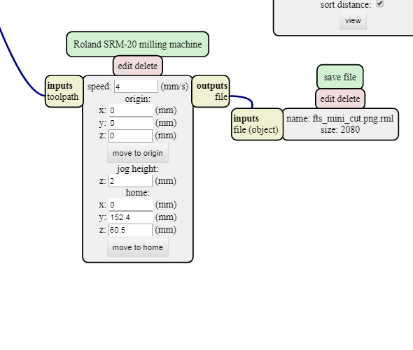
- Speed: This will be the linear speed of the machine. For small details it is better to reduce the speed, but it will take much time to complete the board. I recommend to set it to 3 or 4.
- X, Y and Z origin: Those are the origin coordinates. These values must be 0, and then you will define where the 0,0,0 position is in the machine.
- Jog height: This is the height of the machine while it travels. Make sure to put some value here, if not it will mess up your board. I used 2 mm, but make sure that there will not be any obstacle.
- X, Y and Z Home: This is the position it will go when the cutting is over. you can leave the default one ore change it, just make sure that the Z is high and you do not mess up your design.
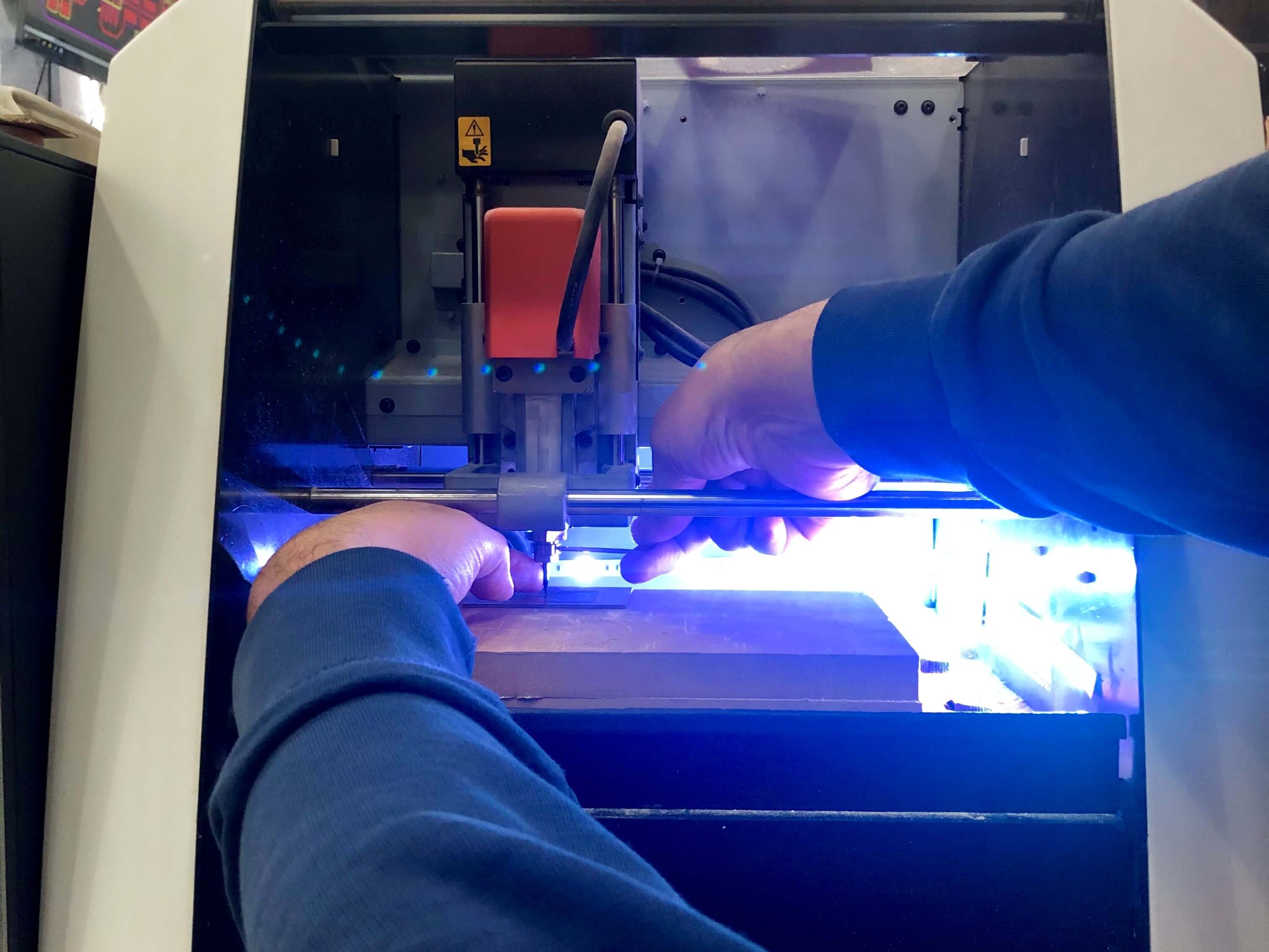
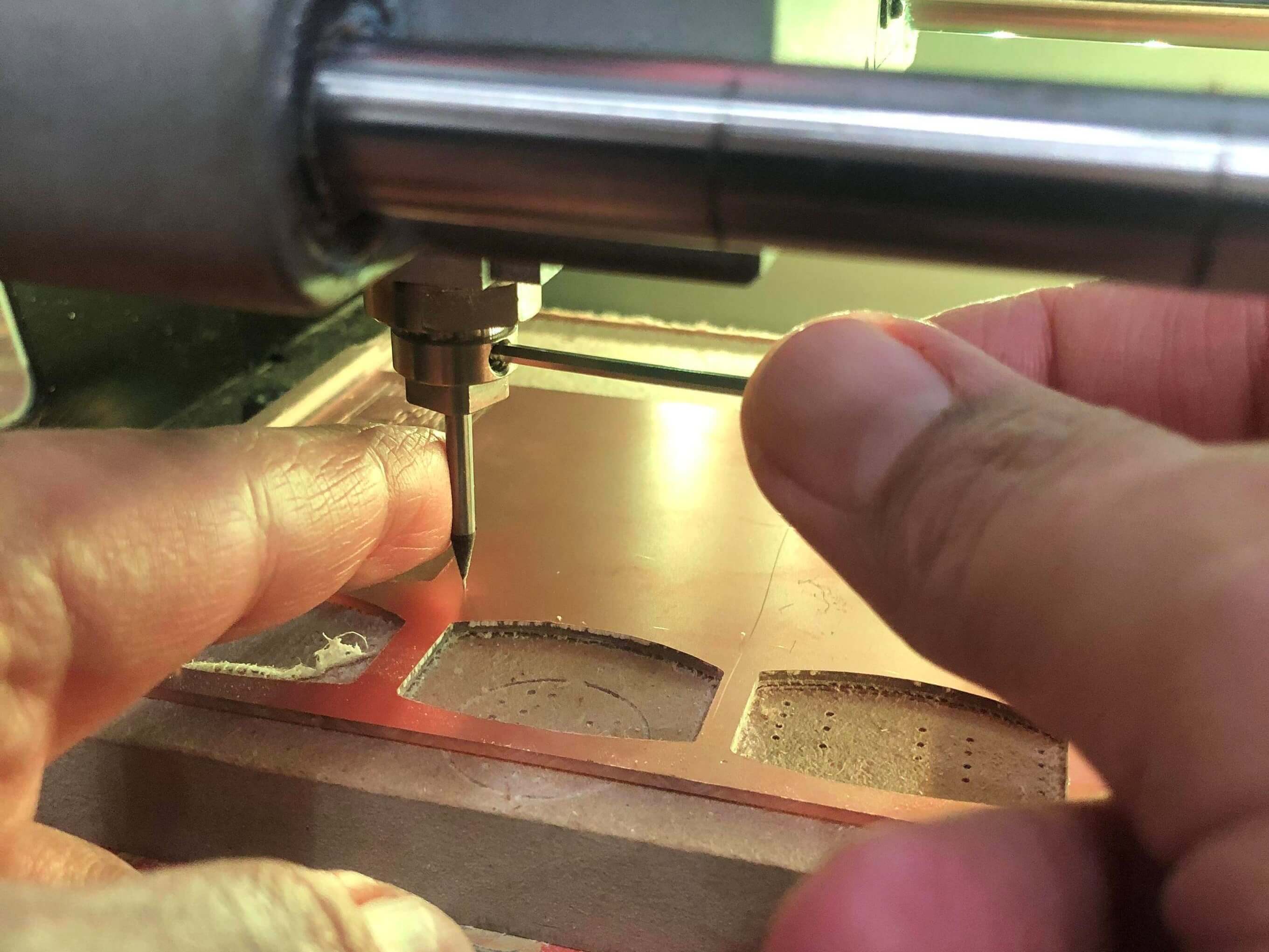
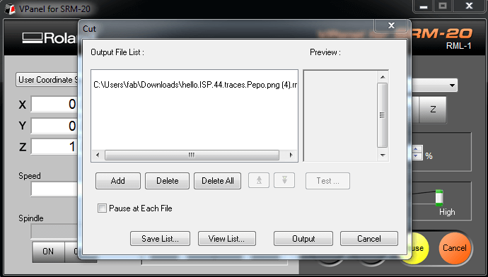
After creating the .rml file, we can prepare the machine. The first thing is to grab the piece of material where you will cut your board and paste it to the plate. To do it, we used 2 face tape, you have to make sure that, if you have more than one tape, they are not touching because putting one on top of the other can create an inclination and a bad result. Then you can connect the machine and set the origin. To do it, first set the XY coordinates. Then approach the Z axis without touching the board, release the drill and when it touches the plate fix it again. Set the Z=0 and raise it a little bit. With the setup done, close the security glass and press Cut. Then a pop-up menu will appear. There you have to delete all previous files, and add yours. When you press Output the machine will start.
After the board is done, we can launch the second file with the borders, remember to change the drill for the 1/32 and set again the Z origin. Do not reset the X and Y origin, if not it can move and your design will not be ok. If it is a little bit dirty, you can clean it with alcohol. This was the result:
Soldring
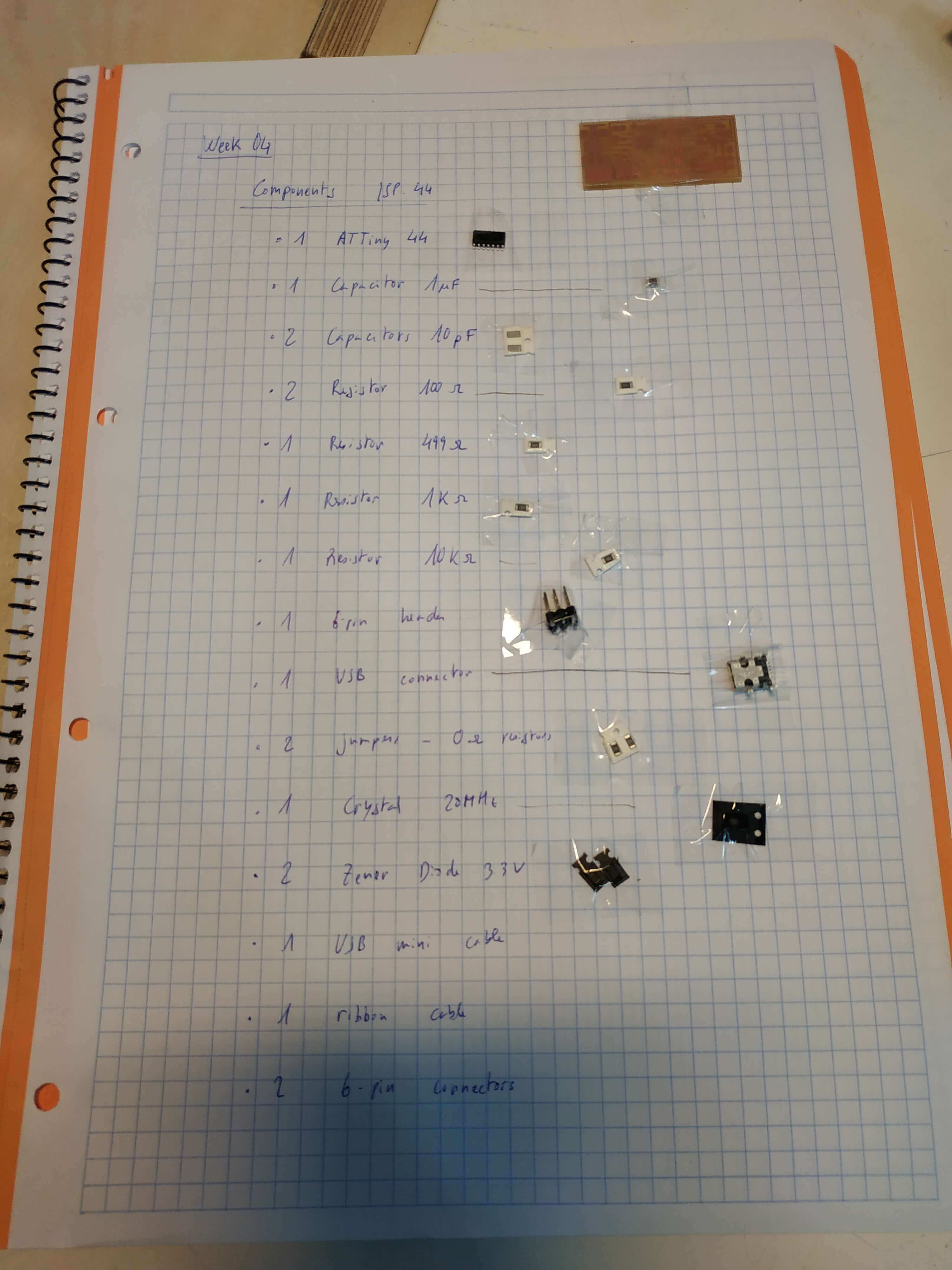
Let's solder! Once we have the board milled, we are going to solder all the components to it. First of all, it is better to organize well, grab all components and prepare for the soldering. I used those images of the components, a finished board and a list with all my components.
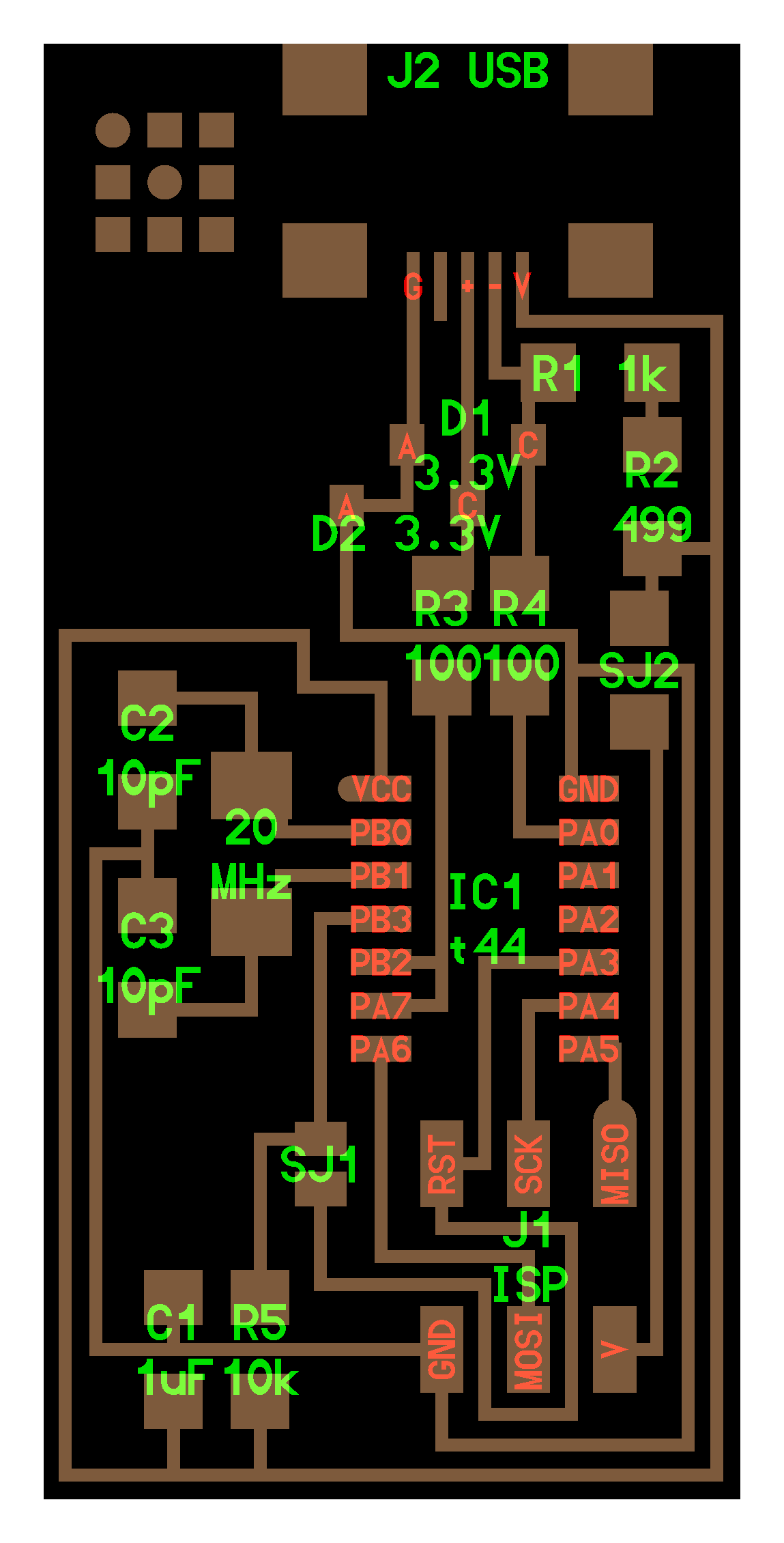
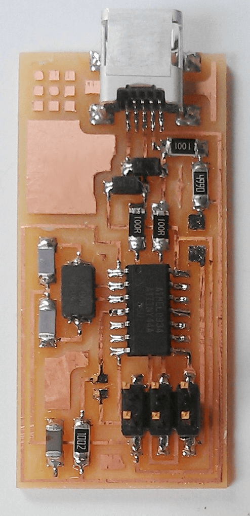
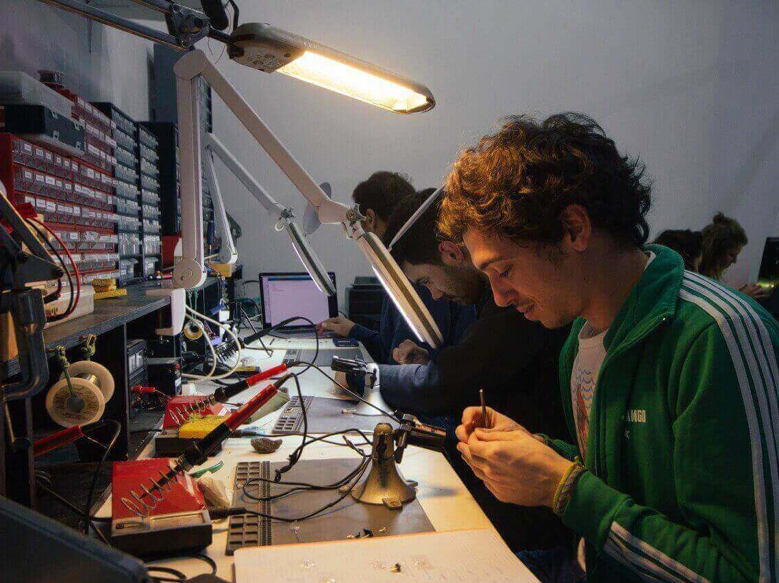
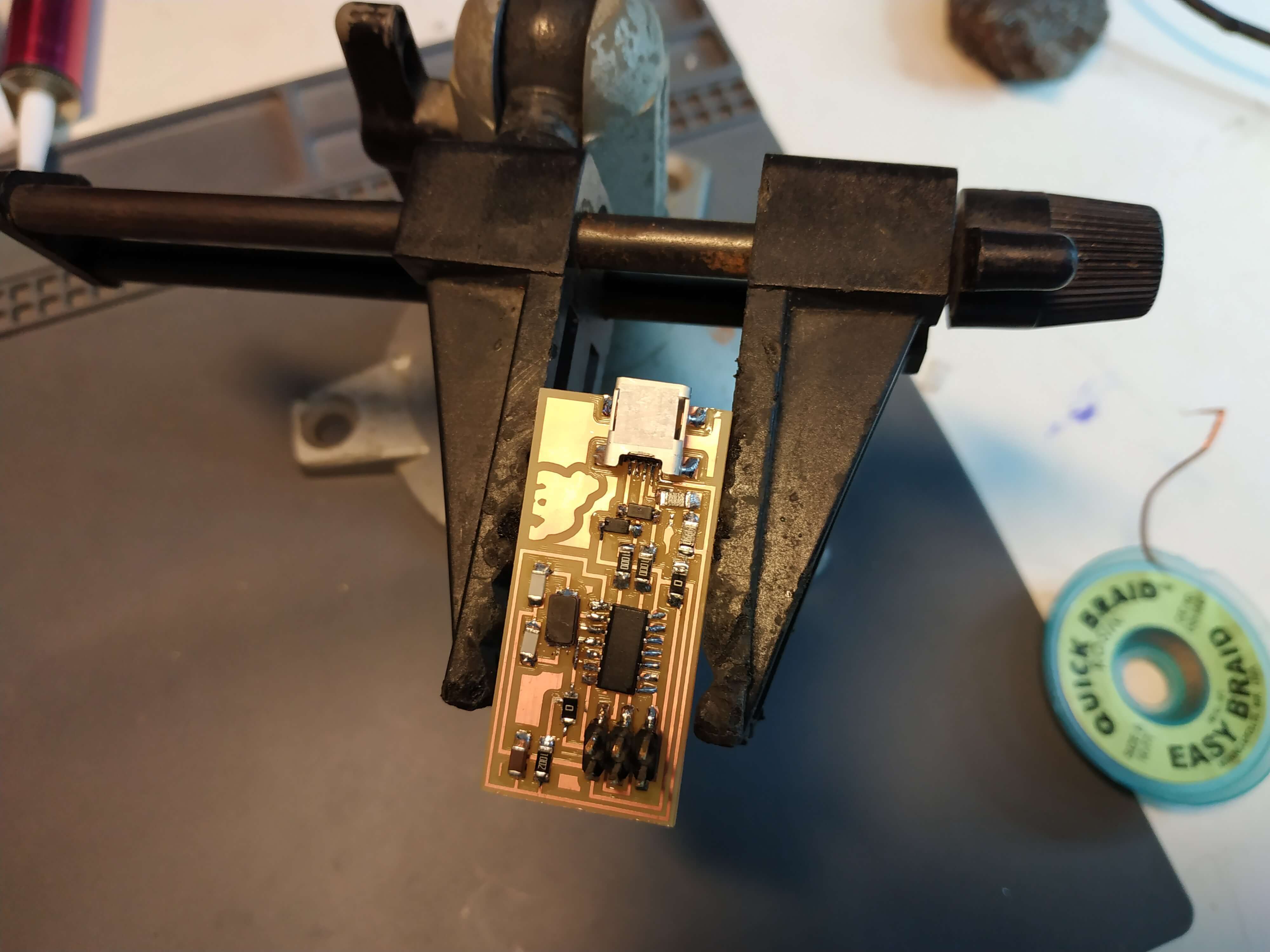
All set up, we can start soldering. The key is a lot of patience and time to do it well. It is really easy to mess up your design. My recommendation is to use tweezers, having good light and have a copper braid around to clear up your mess. This was the result!

Program the ISP
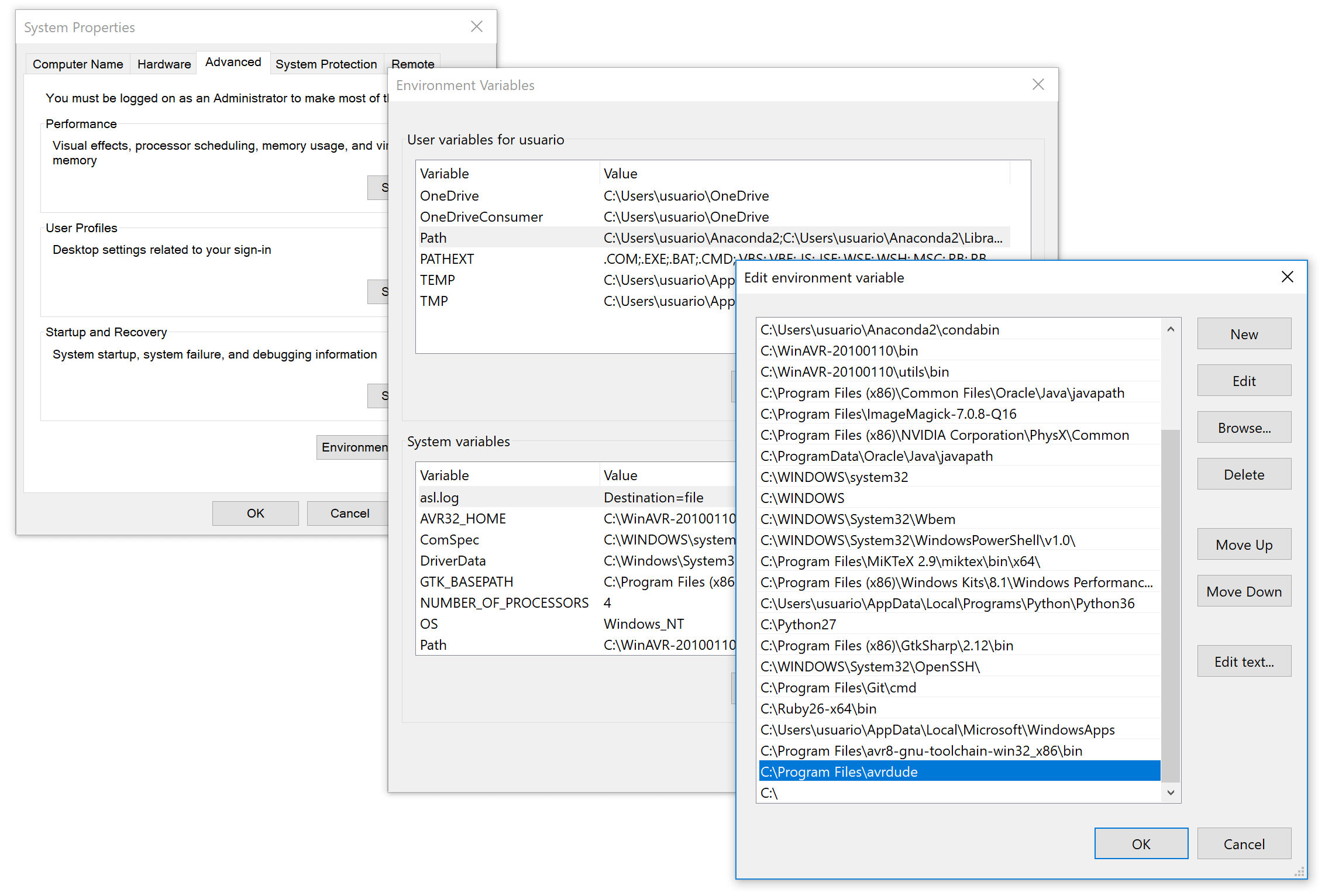
Everything was beautiful until you have to program the chip with a Windows device. Trying to program the ISP with Windows will be a headache, but you can do it! I followed this tutorial and this one. The first thing you have to do is install all the needed software. Install WinAVR. It is not maintained anymore, so it is important to do it carefully. Once it is installed make sure to add the path to your System Enviroment going to Control Panel -> System -> Advanced System Settings -> Enviroment Variables and add to the PATH variable the folder where you have avrdude.exe.
Download the firmware from the assignment webpage and the drivers. You will need another programmer to program your own programmer, we can use the AvrispII or a USBTinny. If you use a USBTinny, it is very important to modify the makefile.txt file and change the next lines:
Before:
#AVRDUDE = avrdude -c usbtiny -p $(DEVICE) # edit this line for your programmer
AVRDUDE = avrdude -c avrispmkII -P usb -p $(DEVICE) # edit this line for your programmer

After:

AVRDUDE = avrdude -c usbtiny -p $(DEVICE) # edit this line for your programmer
#AVRDUDE = avrdude -c avrispmkII -P usb -p $(DEVICE) # edit this line for your programmer
Now it is all set up. Connect the programmer and attach to it your board. If you are using the Avrisp programmer, look to the light indicator. If it is red your board is not correctly powered, you have to connect the mini USB to power it. If it is yellow, the board is powered, but there is a problem with the 6-pin header. Maybe there are a soldering problem or you just connected in the wrong direction. If it is green the connections are OK.
Open a terminal and navigate to the firmware folder. Once there, with luck and a few commands your board will be programmed. Use the next sequence of commands:
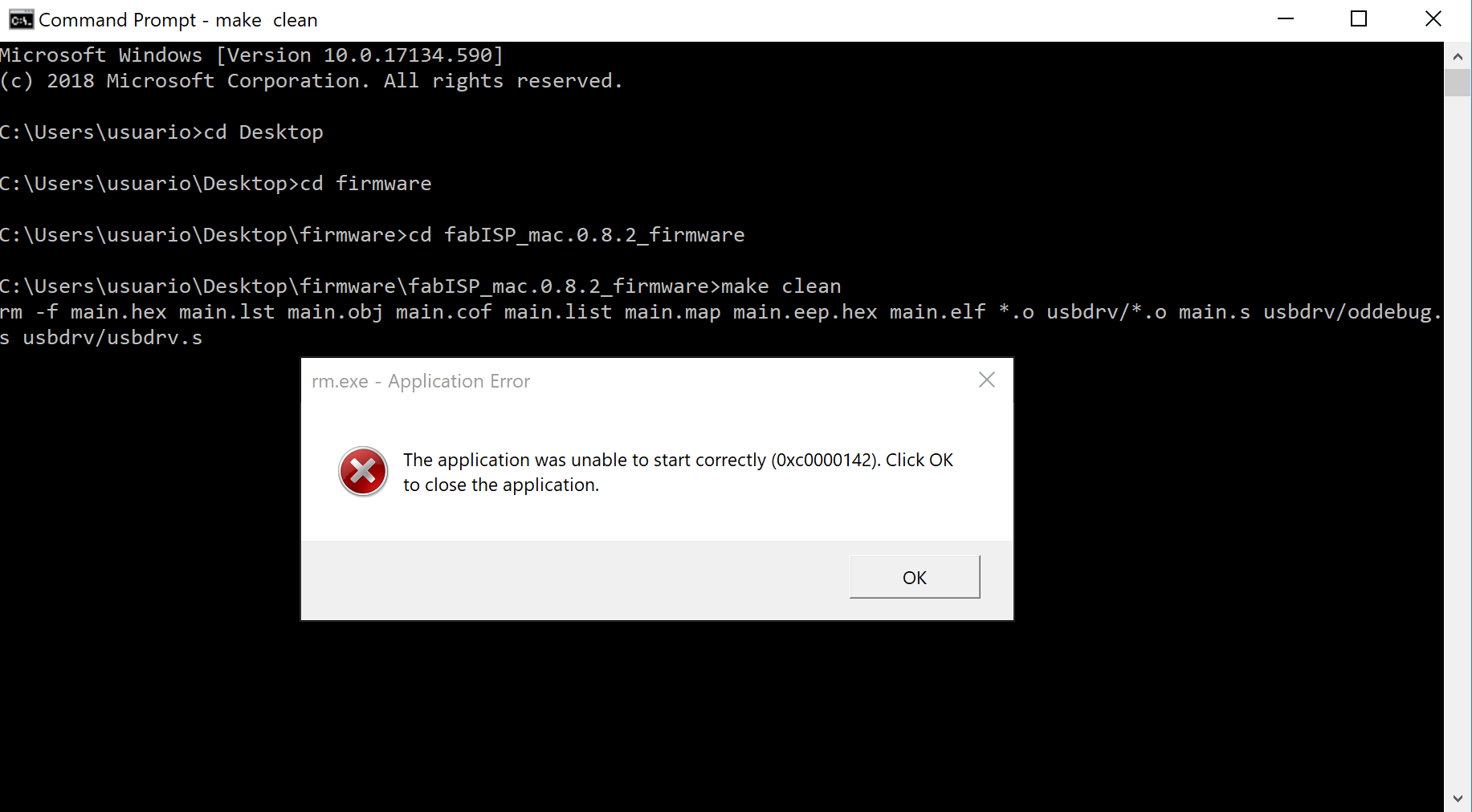
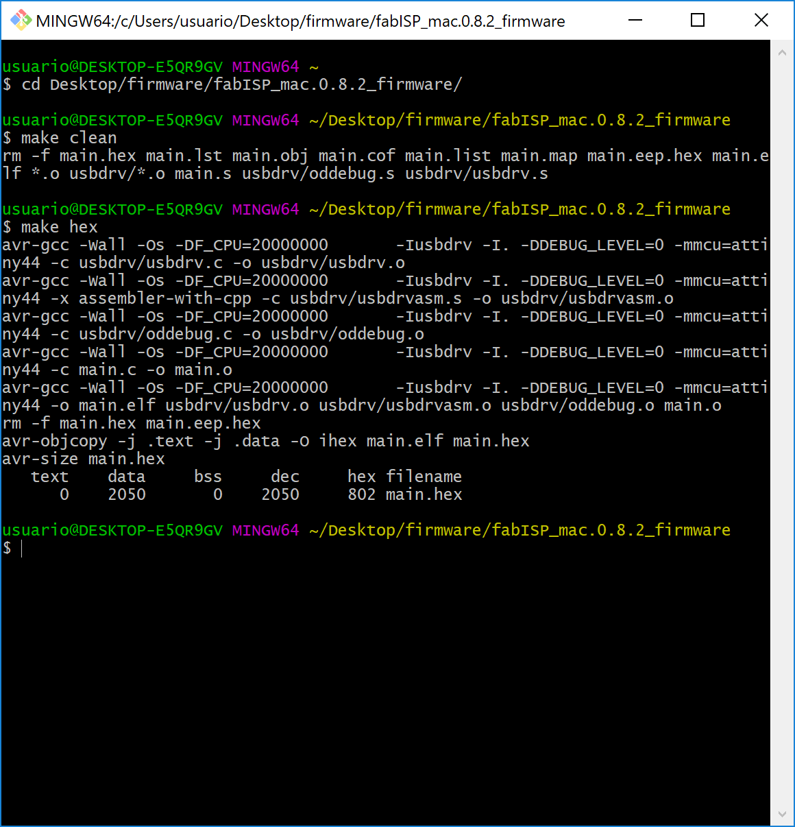
make clean
make hex
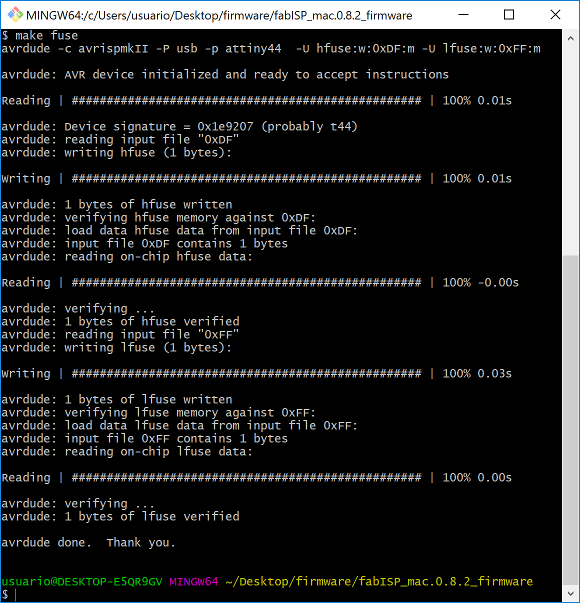
make fuse
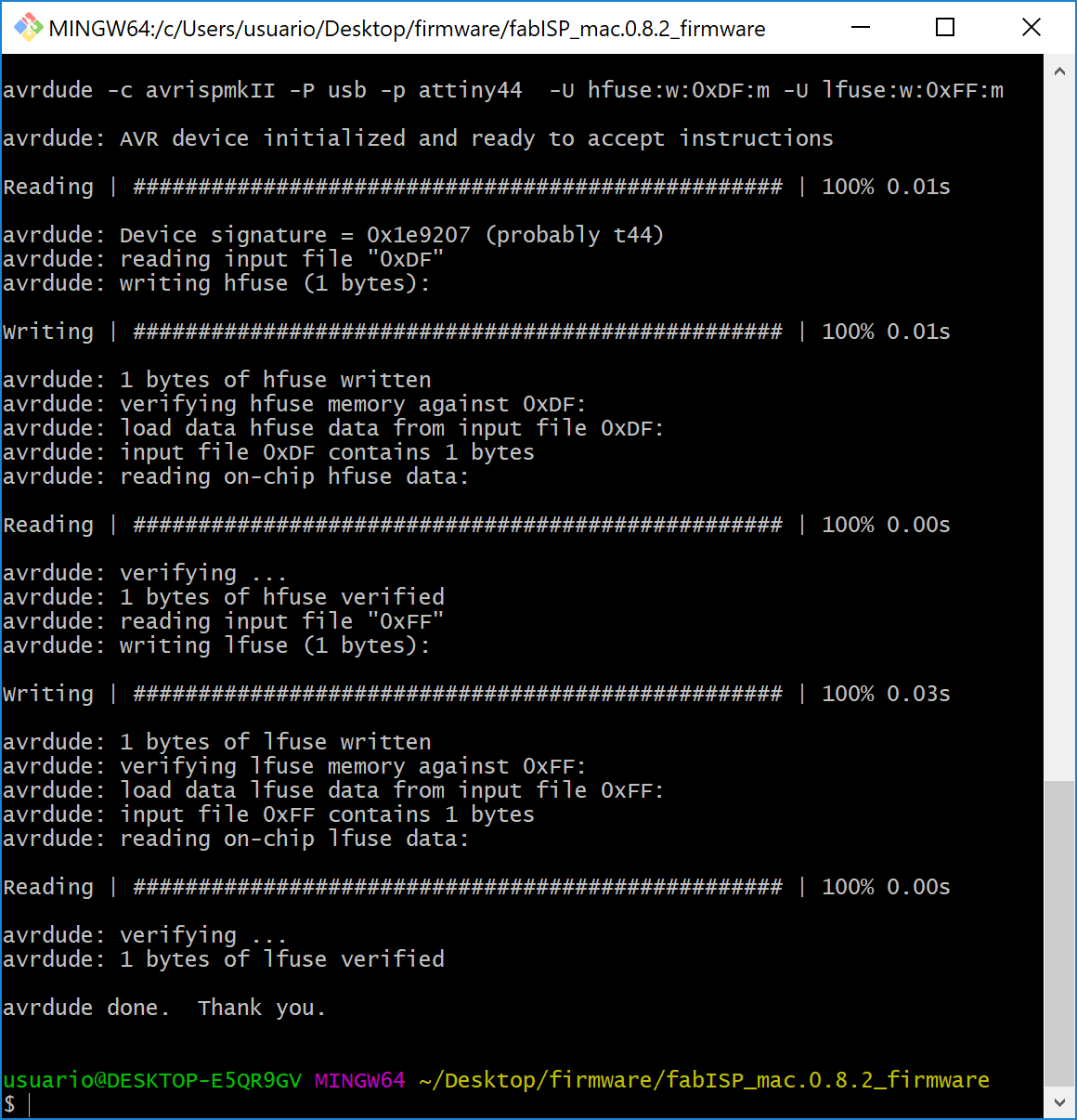
make programIf the commands run without errors your board will be programmed. If there are errors you will have to fight the chip. I face an error after the make clean. This is because you have to add the path first. If not, you can run the commands from the GIT Bash and it will work fine. I also had another problem with the make program command because I had an old version of the avrdude, download the avrdude 6.0 and it will work!
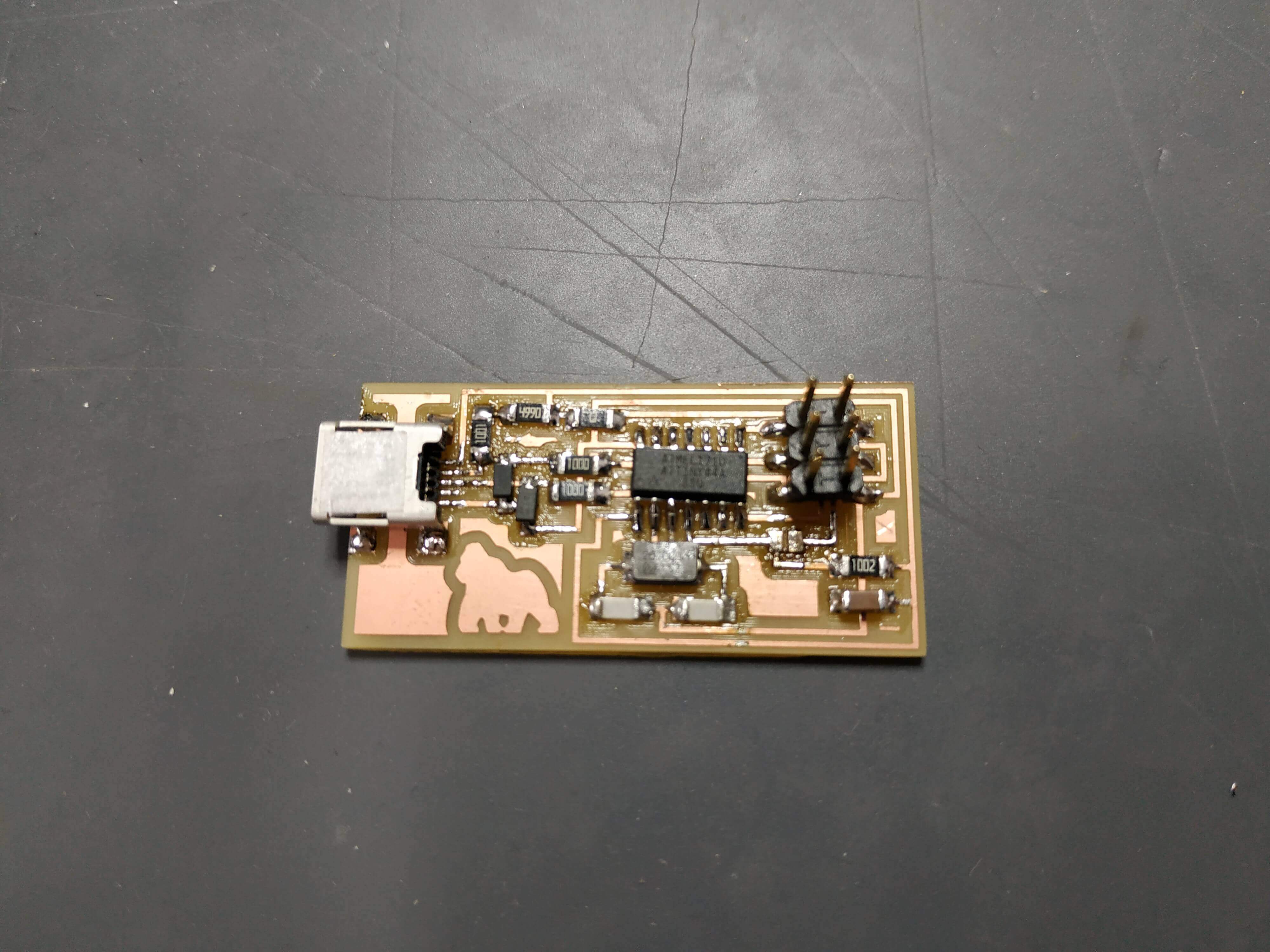
This was the final result, the board was programmed!
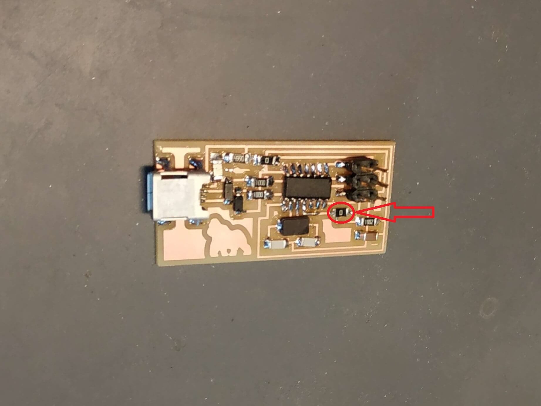
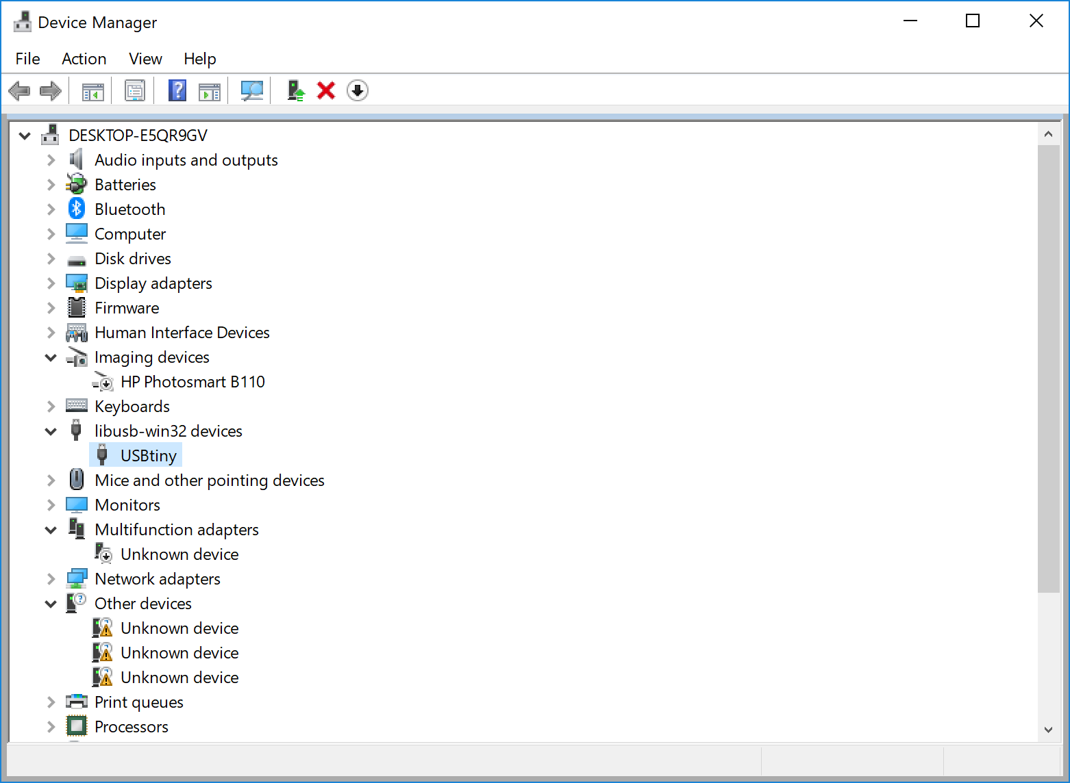
If everything is done well now you can try to connect your board without the programmer and if you find it in the Device Manager it is working! the last step is to remove the 0Ω jumper and you will have your programer.
The problem
In my case, after spending some time to program the board, I did it without any error, but when I connect the board to the computer, it doesn't appear in the Device Manager, so it must be a problem with the USB connection. Now I will have to make sure the soldering is ok and find where it is the problem.
After hours of troubleshooting and testing all connections, the last thing to try was changing the Zener Diodes, and when I change them the problem was solved..! So now my PC can see the board when I connect it to the USB.
Trying to vinyl cut a PCB
With the board finished, I decided to try to cut another ISP with the Vinyl Cutter, but I fialed. I tried to do Alex Board because it has a mini USB entry instead of a USB stick. The problem with a USB entry is that the copper paper will peal out while trying to insert it.
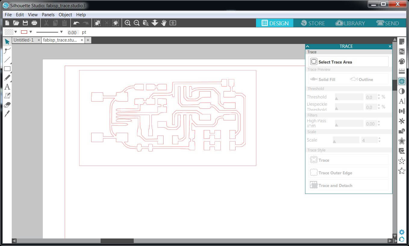
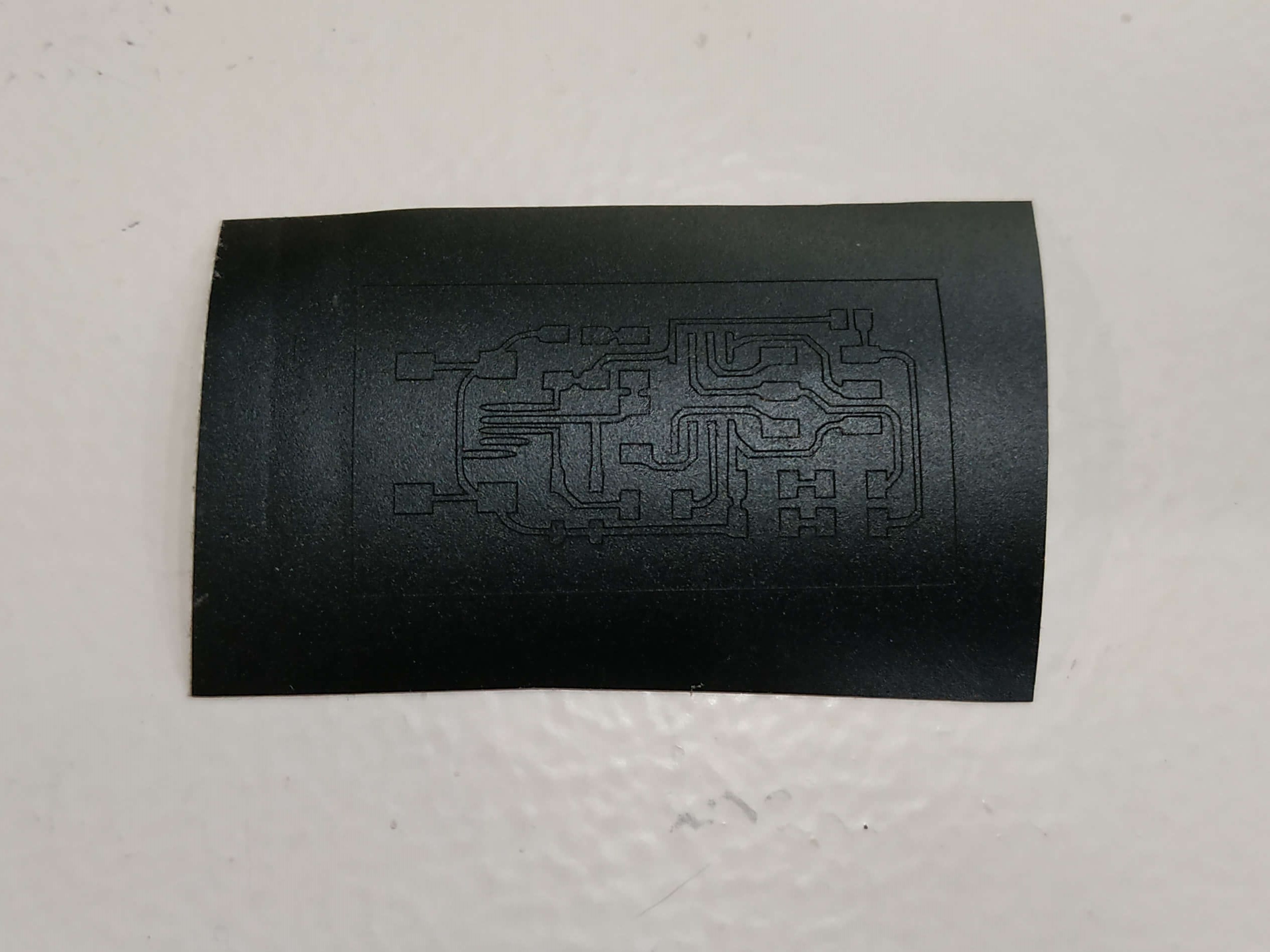
I downloaded the PNG and try to do the traces either in Inkscape and the Silhouette software. The result was great, so I decided to cut it first in a black matte vinyl. The result was great:

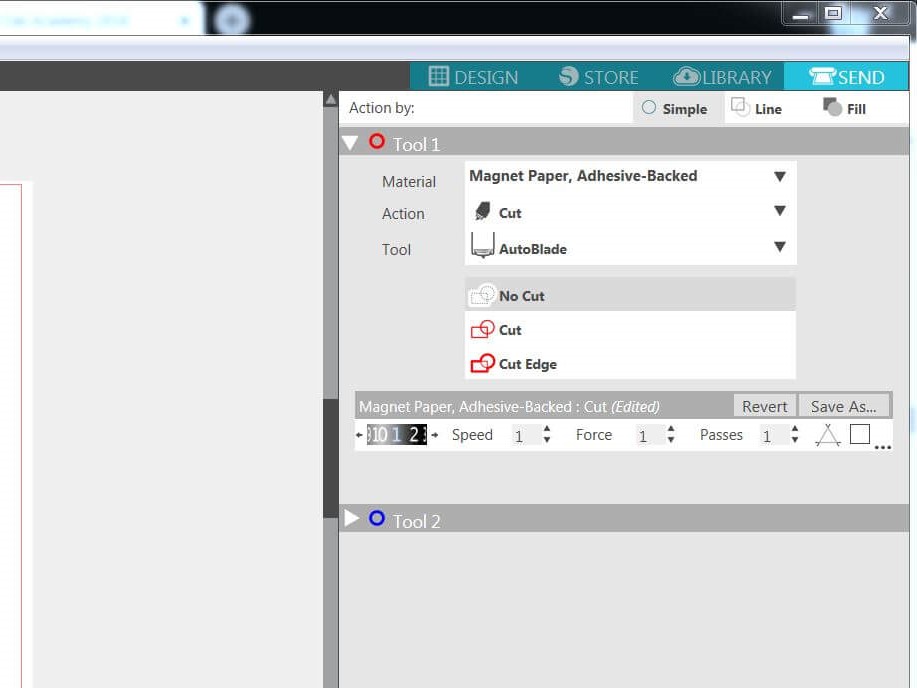
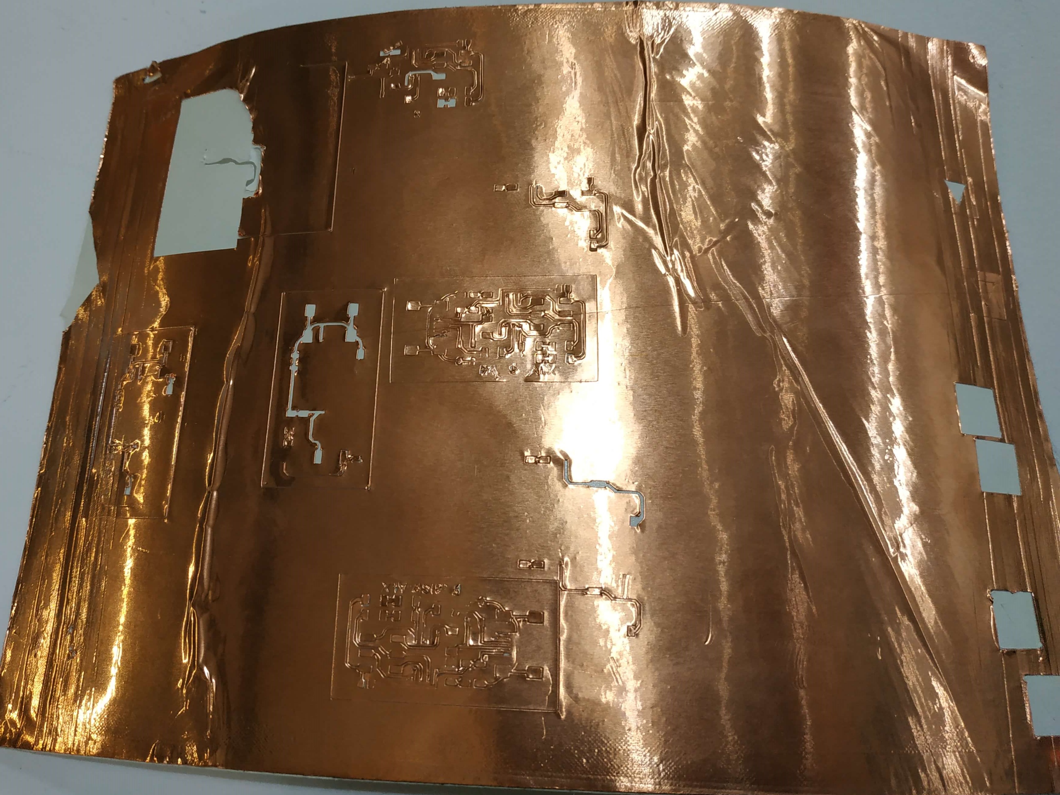
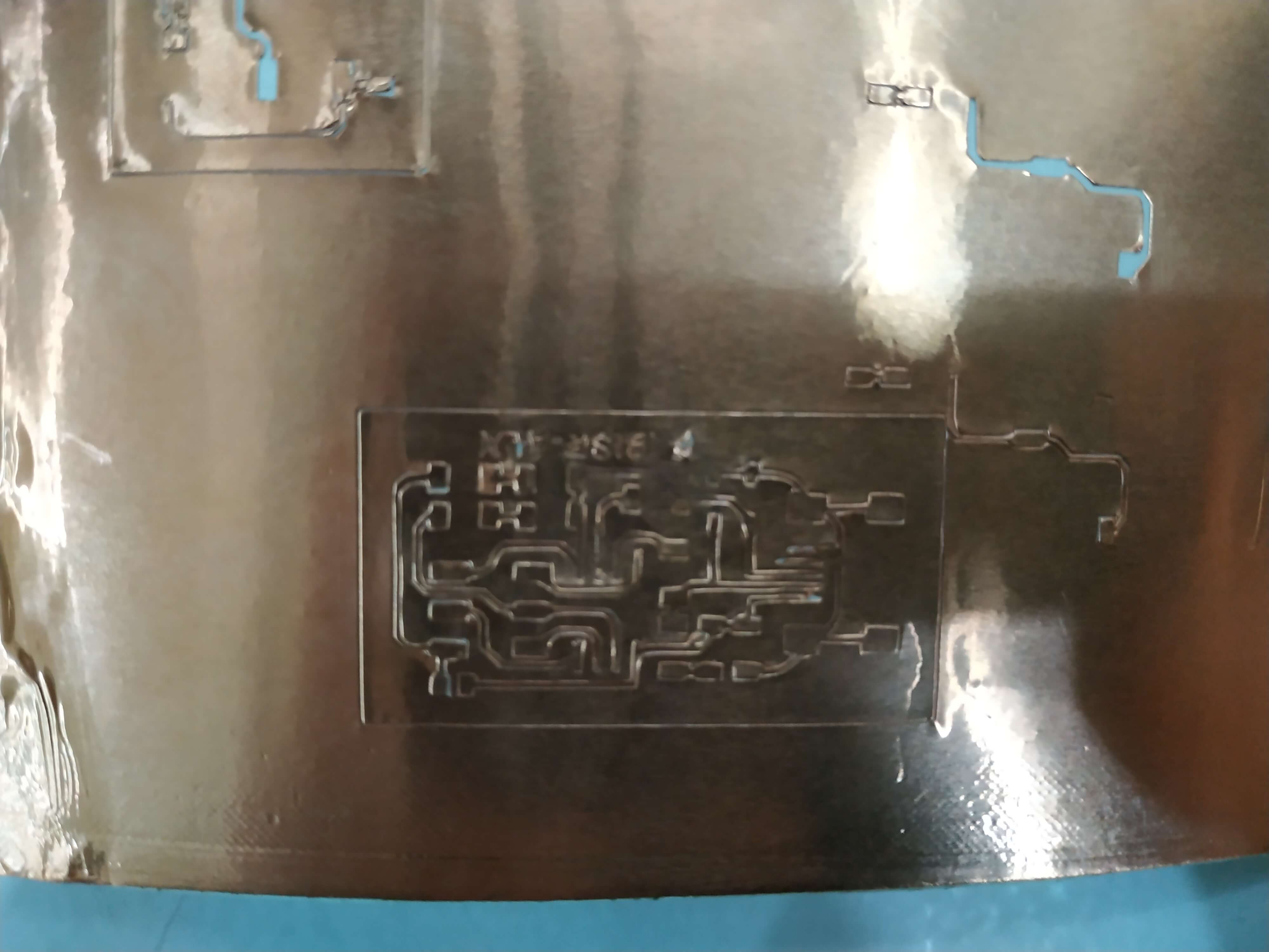
It was time to try with copper vinyl, but the result was not good. I tried with a lot of different settings, changing the speed and force of the machines, but I couldn't get it. The best attempt was with Speed=1 and Force=1 in the Silhouette Cameo, but there were traces that the machine didn't cut. I tried to increase the passes to 2, but then some traces came of and where cutted.
Conclusions
This week was really interesting. I love electronics, but I've never made my own PCB before. Also the soldering part, I had made some solders before, but never in a pcb like this, so it was fun to learn new tips and tricks and discovering things like the copper braid, an amazing invention! I am looking forward to the Electronics Design week! In the meantime, I will try to fix my board and have the full programmer working.