Assignment
individual assignment:
add an output device to a microcontroller board you've designed,
and program it to do something
group assignment:
measure the power consumption of an output device
Individual assignment
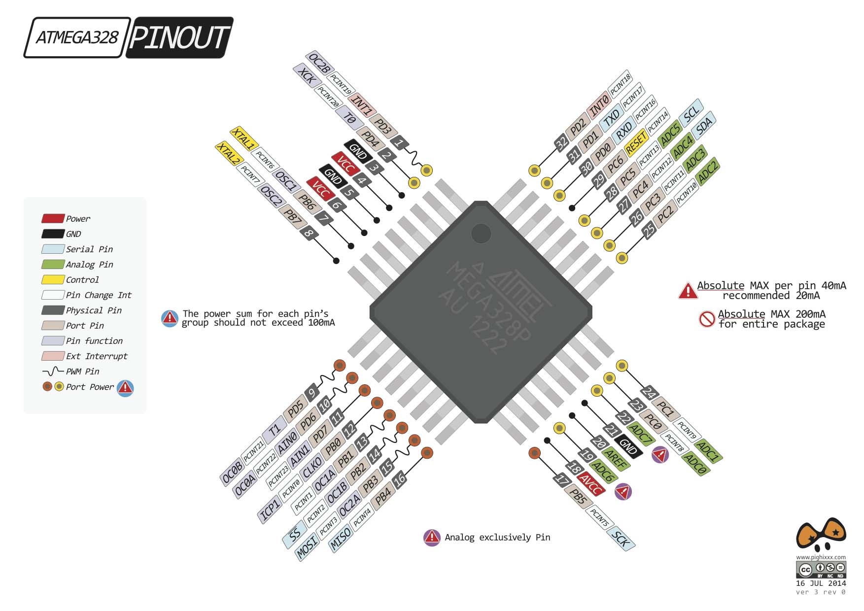
For this assignment I will design a new board with the ATmega328p microcontroller, and test some output devices that I will probably be using in my final project.
Designing the board
I will use Eagle software and refer to satchakit board to design my new board. Check week 7 "Electronic Design" for the detailed steps.
Below is my final sketch.
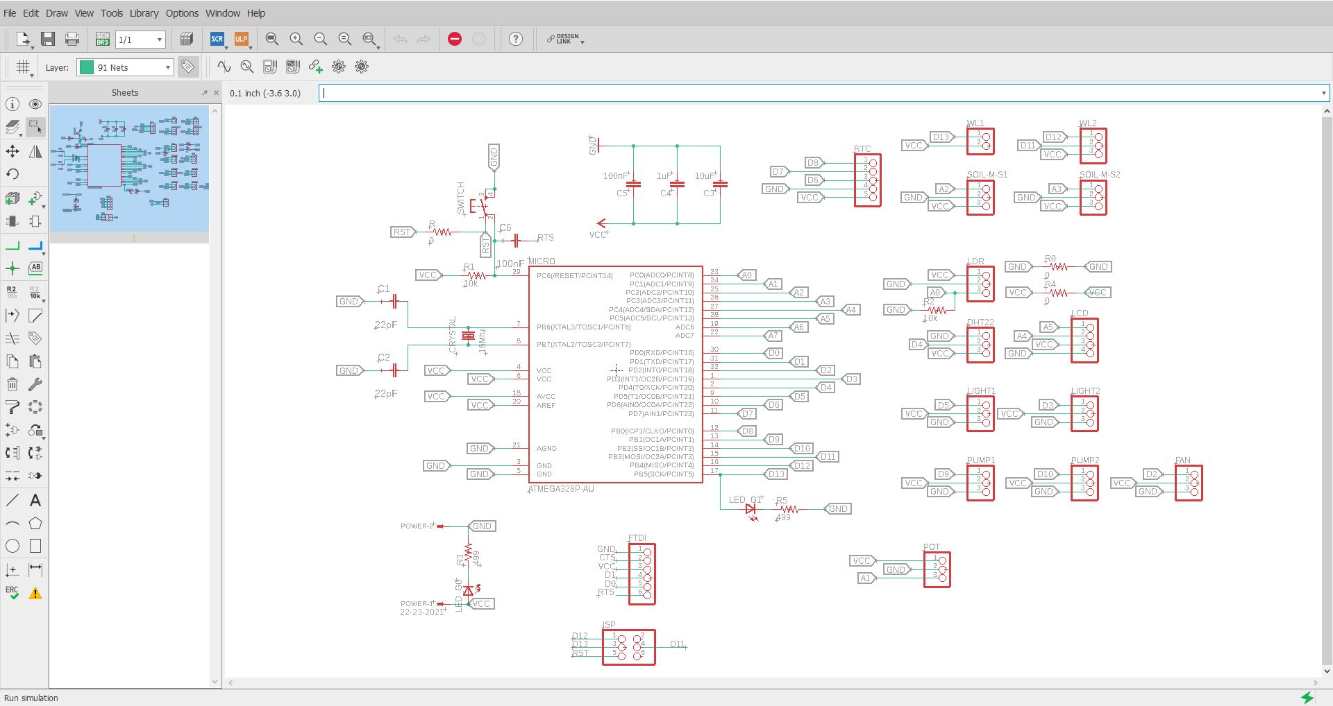
And it will include the following components with their relative Pins:
- The Reset button
- The power Pinhead with a LED and the board capacitors
- The Crystal 16Mhz with the capacitors
- The FTDI connection
- The ISP connection
- A connection for an LDR on Pin A0
- A connection for an potentiometer on Pin A1
- A connection for a Soil moisture sensor1 and Soil moisture sensor2 on Pin A2 and A3.
- A connection for a Liquid Crystal Display LCD on Pin A4 and A5.
- A connection for a Relay on Pin D2 for a FAN
- A connection for a Relay on Pin D3 for a Light
- A connection for a Temperature and Humidity Sensor DHT22 on Pin D4
- A connection for a Relay on Pin D5 for a Grow Light
- A connection for a Real Time Clock module on Pin D6, D7 and D8
- A connection for a Relay on Pin D9 for a Drainage pump
- A connection for a Relay on Pin D10 for a watering pump
- A connection for water level Sensor on Pin D11
- A connection for water level Sensor on Pin D12
- A connection for water level Sensor on Pin D13
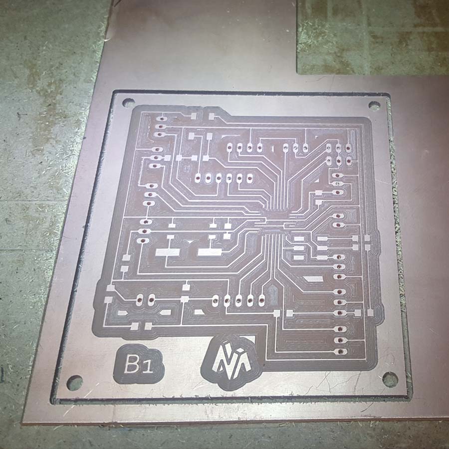
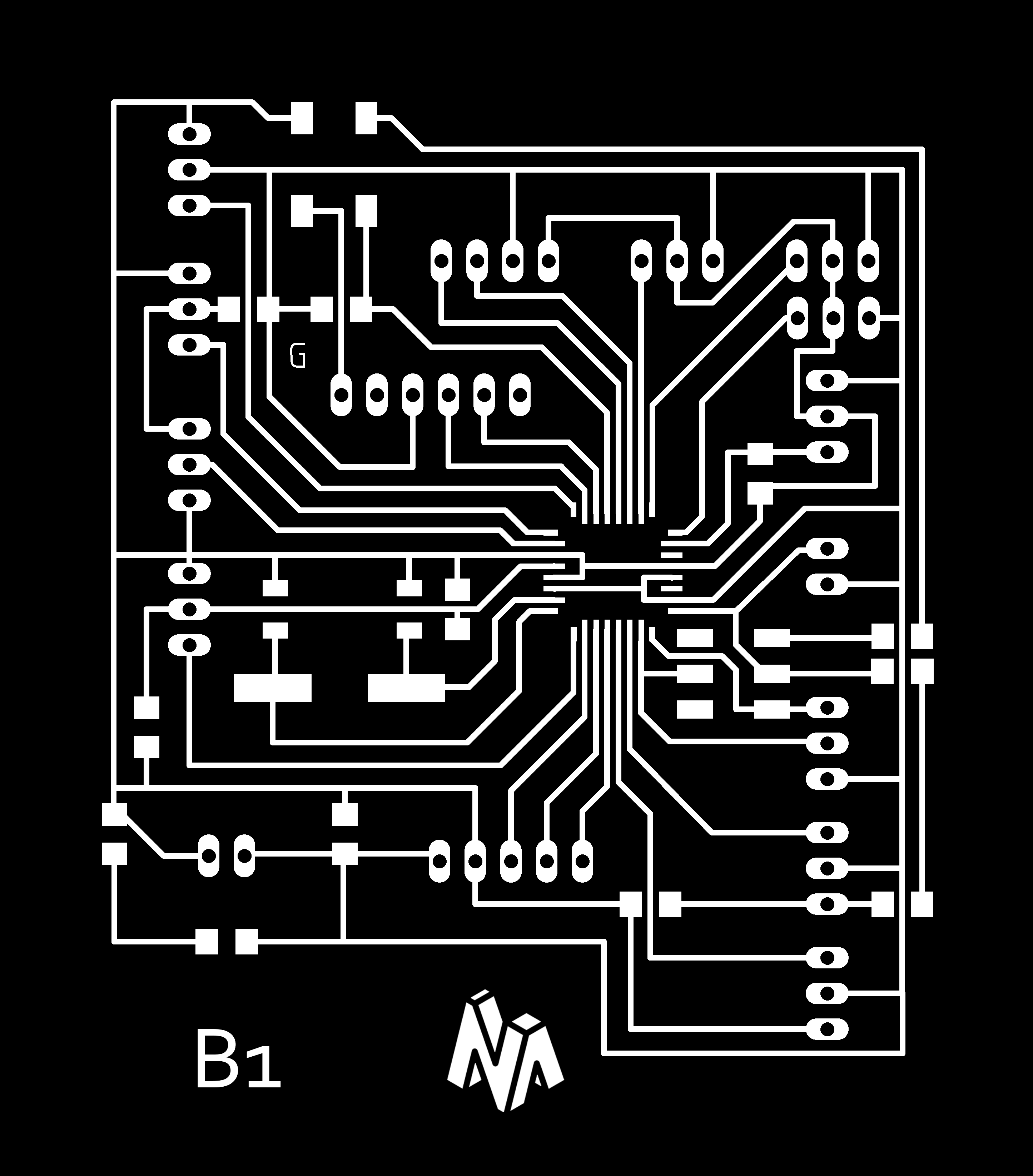
And below is my board design
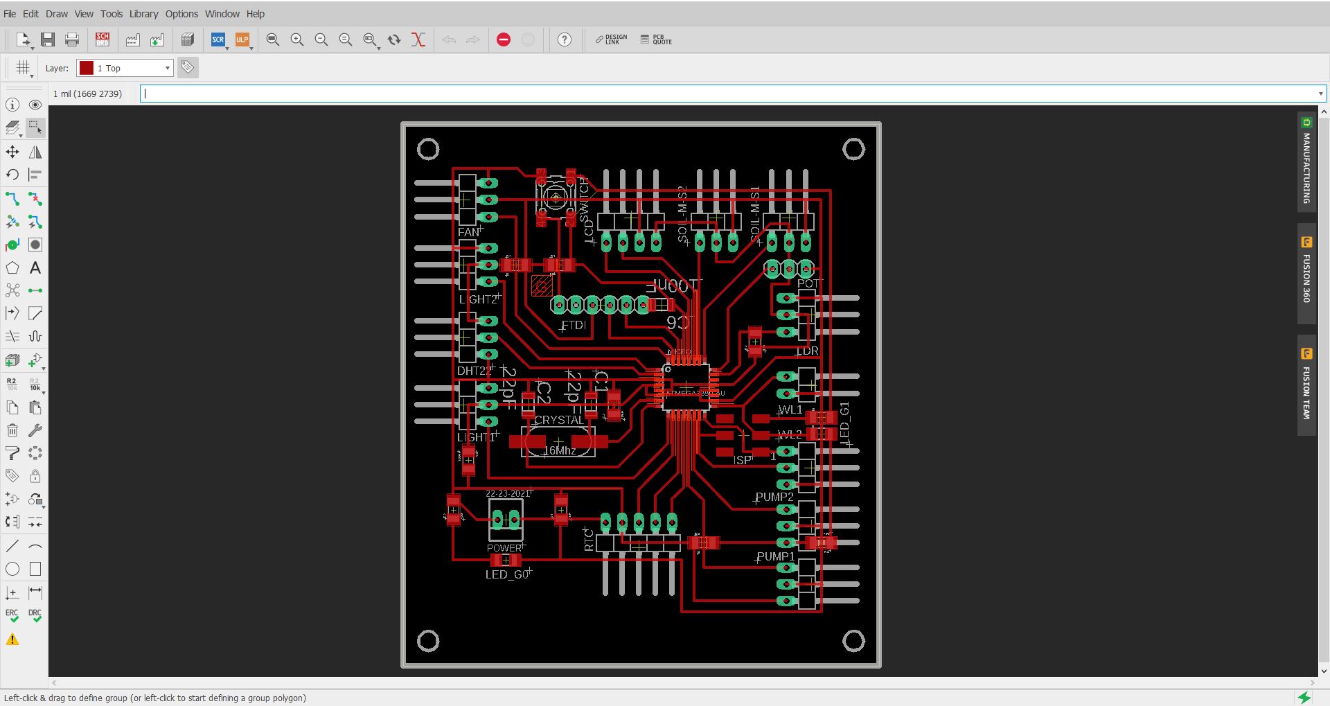
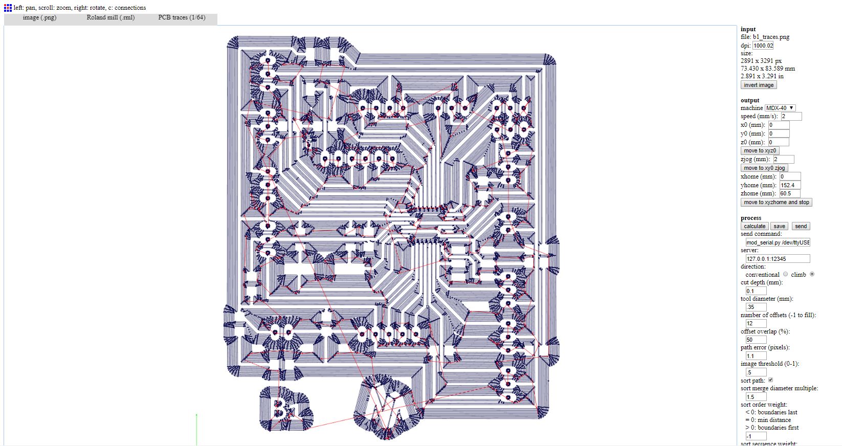
After that, I exported the inner traces image , the drilling image and the cutting image.


And below is the g-code for the inner traces
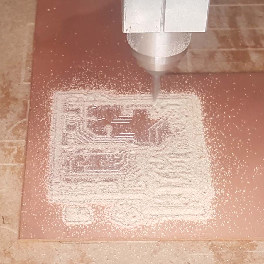
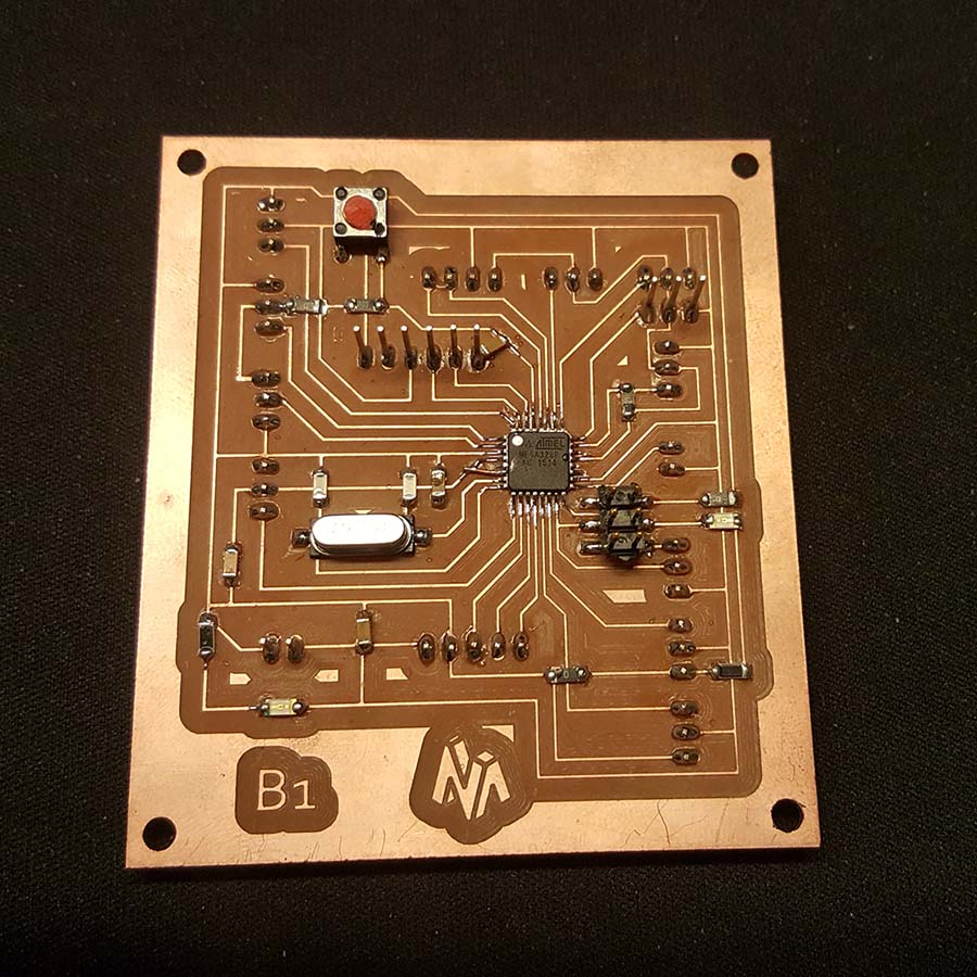
Milling the board and soldering the components
The devices that I will be testing are the following:
- LCD Screen
- Relay
1-LCD Screen
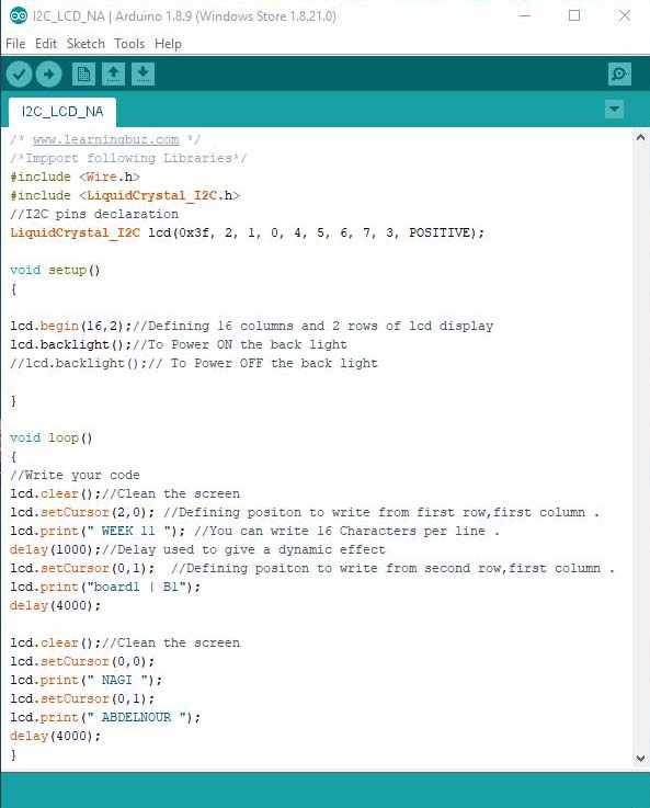
Simple LCD Screen
Below is a simple LCD code :
/* www.learningbuz.com */
/*import following Libraries*/
#include
#include
//I2C pins declaration
LiquidCrystal_I2C lcd(0x3f, 2, 1, 0, 4, 5, 6, 7, 3, POSITIVE);
void setup()
{
lcd.begin(16,2);//Defining 16 columns and 2 rows of lcd display
lcd.backlight();//To Power ON the back light
//lcd.backlight();// To Power OFF the back light
}
void loop()
{
//Write your code
lcd.clear();//Clean the screen
lcd.setCursor(2,0); //Defining position to write from first row,first column .
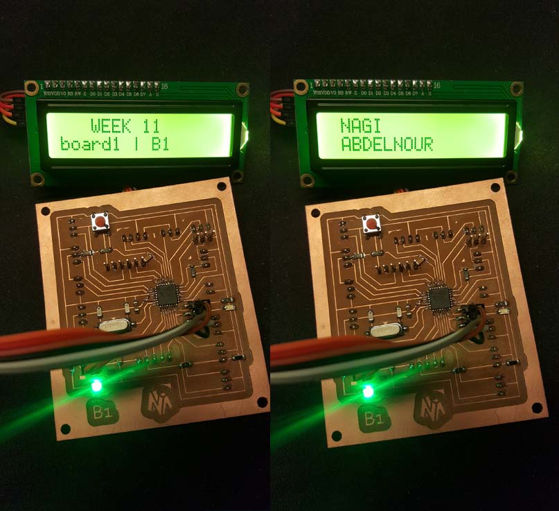
lcd.print(" WEEK 11 "); //You can write 16 Characters per line .
delay(1000);//Delay used to give a dynamic effect
lcd.setCursor(0,1); //Defining position to write from second row,first column .
lcd.print("board1 | B1");
delay(4000);
lcd.clear();//Clean the screen
lcd.setCursor(0,0);
lcd.print(" NAGI ");
lcd.setCursor(0,1);
lcd.print(" ABDELNOUR ");
delay(4000);
}
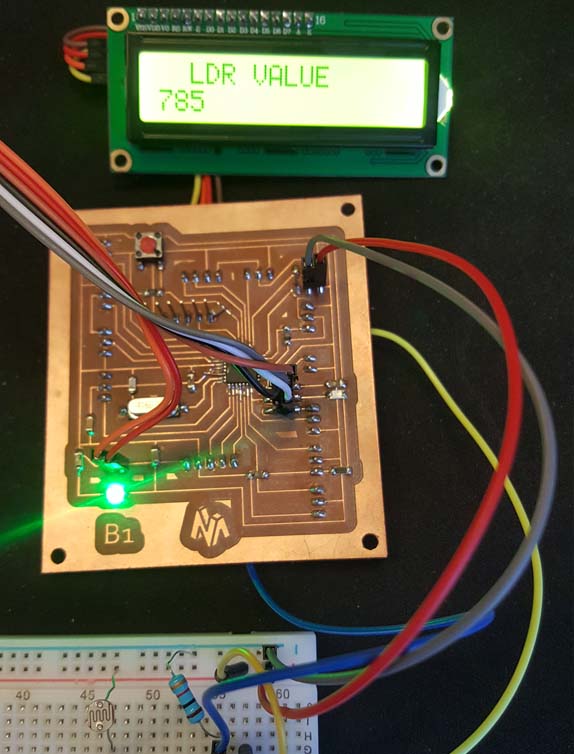
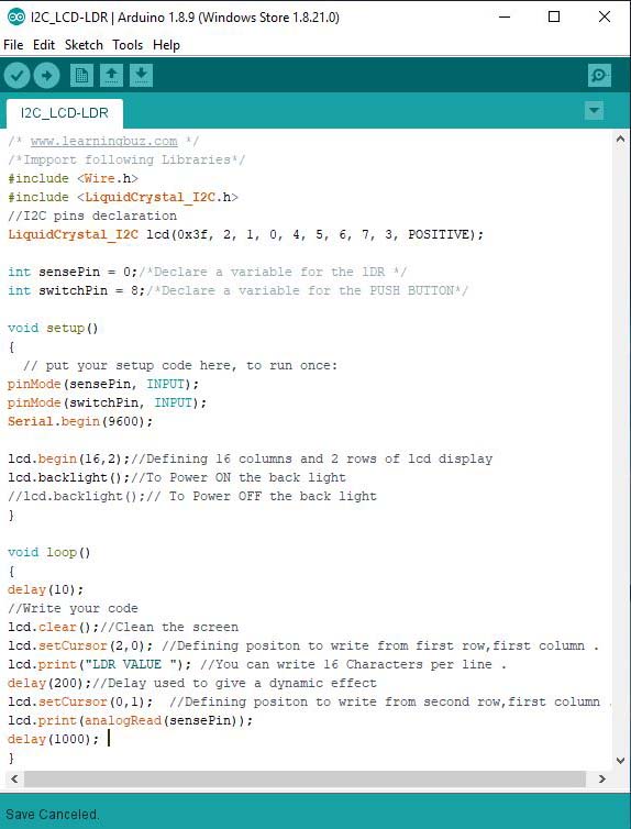
LCD Screen with LDR
I will connect the LDR to pin A0 and monitor the value on the LCD and below is the new code.
                            /* www.learningbuz.com */
                            /*import following Libraries*/
                            #include
                                #include
                                    //I2C pins declaration
                                    LiquidCrystal_I2C lcd(0x3f, 2, 1, 0, 4, 5, 6, 7, 3, POSITIVE);

                                    int sensePin = 0;/*Declare a variable for the lDR */
                                    int switchPin = 8;/*Declare a variable for the PUSH BUTTON*/

                                    void setup()
                                    {
                                    // put your setup code here, to run once:
                                    pinMode(sensePin, INPUT);
                                    pinMode(switchPin, INPUT);
                                    Serial.begin(9600);

                                    lcd.begin(16,2);//Defining 16 columns and 2 rows of lcd display
                                    lcd.backlight();//To Power ON the back light
                                    //lcd.backlight();// To Power OFF the back light
                                    }

                                    void loop()
                                    {
                                    delay(10);
                                    //Write your code
                                    lcd.clear();//Clean the screen
                                    lcd.setCursor(2,0); //Defining position to write from first row,first column .
                                    lcd.print("LDR VALUE "); //You can write 16 Characters per line .
                                    delay(200);//Delay used to give a dynamic effect
                                    lcd.setCursor(0,1); //Defining position to write from second row,first column .
                                    lcd.print(analogRead(sensePin));
                                    delay(1000);
                                    }
2-Relay
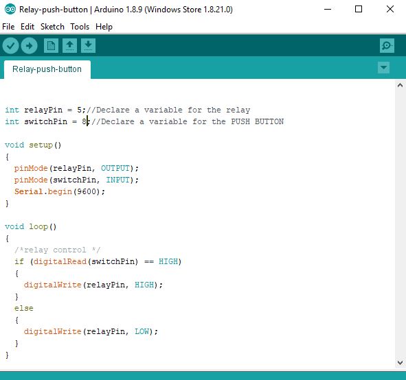
Relay with a Push button
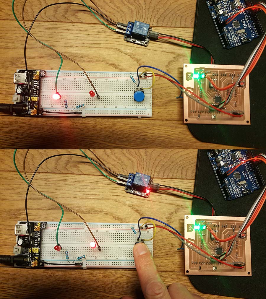
A relay is an electrically operated switch: it has a Signal port , a VCC and a GND port connected to my board from one side and an independent circuit from the other side that has a common port , a normally closed (NC) port and a normally open (NO) port
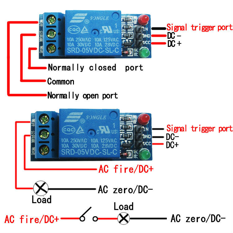
When a component is attached to the normally closed port, it means that when the signal coming from the board is low the loop is closed and vice versa.
Below is a simple code with 2 leds connected to the relay , one on the NC and the other on the NO from one side and a push button signal connected to my board from the other side: when nothing is pushed the led connected to the NC will turn on and when we press the button the led connected to the NO will turn on and the other one will turn off.
                            int relayPin = 5;//Declare a variable for the relay
                            int switchPin = 8;//Declare a variable for the PUSH BUTTON

                            void setup()
                            {
                            pinMode(relayPin, OUTPUT);
                            pinMode(switchPin, INPUT);
                            Serial.begin(9600);
                            }

                            void loop()
                            {
                            /*relay control */
                            if (digitalRead(switchPin) == HIGH)
                            {
                            digitalWrite(relayPin, HIGH);
                            }
                            else
                            {
                            digitalWrite(relayPin, LOW);
                            }
                            }
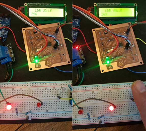
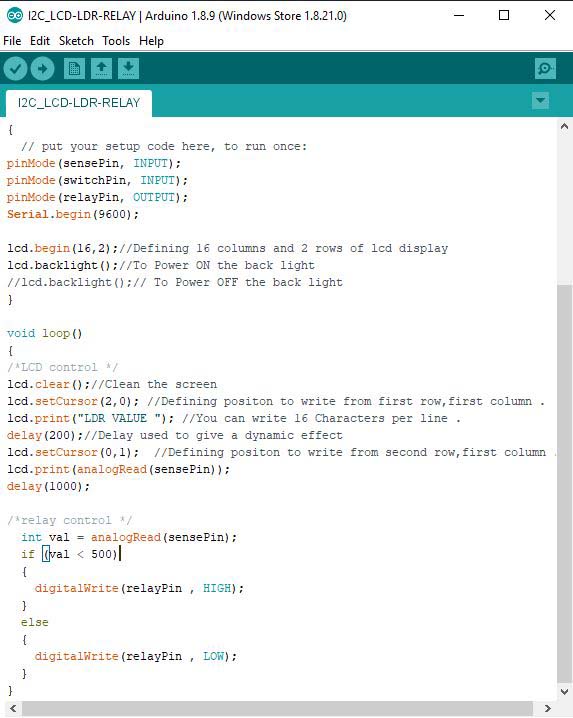
Relay with the LDR and the LCD
Now I will connect the LDR and the LCD , below is the new code : when the LDR value is under 500 the relay will be activated and the led connected to the NO will turn on and the other one will turn off.
                            /* www.learningbuz.com */
                            /*Impport following Libraries*/
                            #include
                                #include
                                    //I2C pins declaration
                                    LiquidCrystal_I2C lcd(0x3f, 2, 1, 0, 4, 5, 6, 7, 3, POSITIVE);

                                    int sensePin = 0;/*Declare a variable for the lDR */
                                    int switchPin = 8;/*Declare a variable for the PUSH BUTTON*/
                                    int relayPin = 5;/*Declare a variable for the relay*/

                                    void setup()

                                    {
                                    // put your setup code here, to run once:
                                    pinMode(sensePin, INPUT);
                                    pinMode(switchPin, INPUT);
                                    pinMode(relayPin, OUTPUT);
                                    Serial.begin(9600);

                                    lcd.begin(16,2);//Defining 16 columns and 2 rows of lcd display
                                    lcd.backlight();//To Power ON the back light
                                    //lcd.backlight();// To Power OFF the back light
                                    }

                                    void loop()
                                    {
                                    /*LCD control */
                                    lcd.clear();//Clean the screen
                                    lcd.setCursor(2,0); //Defining position to write from first row,first column .
                                    lcd.print("LDR VALUE "); //You can write 16 Characters per line .
                                    delay(200);//Delay used to give a dynamic effect
                                    lcd.setCursor(0,1); //Defining position to write from second row,first column .
                                    lcd.print(analogRead(sensePin));
                                    delay(1000);

                                    /*relay control */
                                    int val = analogRead(sensePin);
                                    if (val < 500) { digitalWrite(relayPin , HIGH); } else { digitalWrite(relayPin , LOW); } }
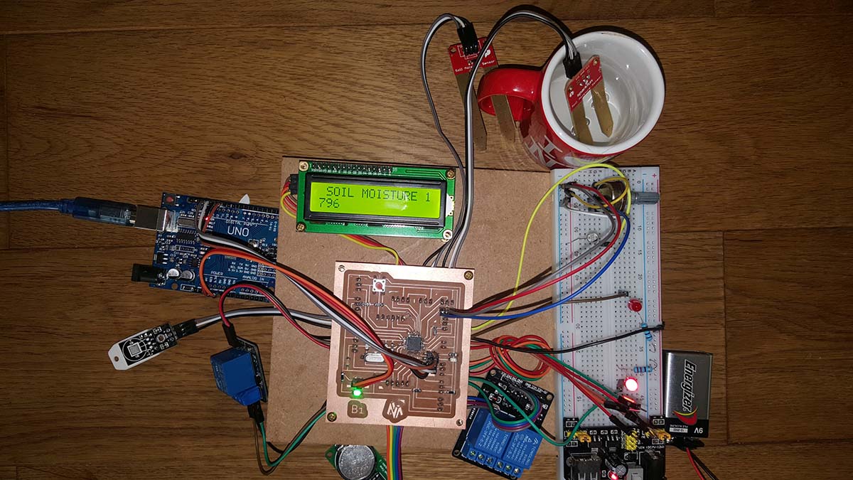
INPUTS / OUTPUTS
Now I will connect all my input / output sensors and play with my code
                            /*import following Libraries*/
                            #include
                                #include
                                    LiquidCrystal_I2C lcd(0x3f, 2, 1, 0, 4, 5, 6, 7, 3, POSITIVE); //I2C pins declaration
                                    // Load the virtuabotixRTC library
                                    #include
                                        // myRTC (clock, data, RST)
                                        virtuabotixRTC myRTC (6, 7, 8);// Determine the pins connected to the module
                                        //Load the DHT library
                                        #include
                                            dht DHT;
                                            #define DHT22_PIN 4 // DHT 22 (AM2302) - what pin we're connected to

                                            //Variables
                                            float hum; //Stores humidity value
                                            float temp; //Stores temperature value


                                            int sensePin = 0;/*Declare a variable for the lDR */
                                            int potPin = A1;/*Declare a variable for the Potentiometer */
                                            int soilPin1 = A2;/*Declare a variable for the soil moisture sensor 1 */
                                            int soilPin2 = A3;/*Declare a variable for the soil moisture sensor 2 */
                                            int waterLev1 = 11;/*Declare a variable for the water level 1(for pot1) */
                                            int waterLev2 = 12;/*Declare a variable for the water level 2 (for pot2) */
                                            int waterLev3 = 13;/*Declare a variable for the water level 3 (for water tank) */
                                            int relayPinF = 2;/*Declare a variable for the relay / FAN */
                                            int relayPinL1 = 5;/*Declare a variable for the relay / LIGHT1 */
                                            int relayPinL2 = 3;/*Declare a variable for the relay / LIGHT2 */
                                            int relayPinP1 = 9;/*Declare a variable for the relay / PUMP1 */
                                            int relayPinP2 = 10;/*Declare a variable for the relay / PUMP2 */


                                            void setup()

                                            {
                                            // put your setup code here, to run once:
                                            pinMode(sensePin, INPUT);
                                            pinMode(potPin, INPUT);
                                            pinMode(soilPin1, INPUT);
                                            pinMode(soilPin2, INPUT);
                                            pinMode(waterLev1, INPUT);
                                            pinMode(waterLev2, INPUT);
                                            pinMode(waterLev3, INPUT);

                                            pinMode(relayPinF, OUTPUT);
                                            pinMode(relayPinL1, OUTPUT);
                                            pinMode(relayPinL2, OUTPUT);
                                            pinMode(relayPinP1, OUTPUT);
                                            pinMode(relayPinP2, OUTPUT);
                                            Serial.begin(9600);

                                            lcd.begin(16, 2); //Defining 16 columns and 2 rows of lcd display
                                            lcd.backlight();//To Power ON the back light
                                            //lcd.backlight();// To Power OFF the back light

                                            // After to set the entire information, comment the following line
                                            // (seconds, minutes, hours, day of week, day of month, month, year)
                                            myRTC.setDS1302Time (50, 13, 11, 2, 9, 4, 2019);
                                            }

                                            void loop()
                                            {
                                            /*Reads the information from the CI */
                                            myRTC.updateTime ();

                                            /*dht control */
                                            int chk = DHT.read22(DHT22_PIN);//Read data and store it to variables hum and temp
                                            hum = DHT.humidity;
                                            temp = DHT.temperature;

                                            /*LCD control */
                                            lcd.clear();//Clean the screen
                                            lcd.setCursor(2, 0); //Defining position to write from first row,first column .
                                            lcd.print("LDR VALUE "); //You can write 16 Characters per line .
                                            delay(200);//Delay used to give a dynamic effect
                                            lcd.setCursor(0, 1); //Defining position to write from second row,first column .
                                            lcd.print(analogRead(sensePin));
                                            delay(1000);

                                            lcd.clear();//Clean the screen
                                            lcd.setCursor(0, 0);
                                            lcd.print(" TEMP ");
                                            lcd.setCursor(0, 1);
                                            lcd.print(temp);
                                            delay(1000);

                                            lcd.clear();//Clean the screen
                                            lcd.setCursor(0, 0);
                                            lcd.print(" HUMIDITY ");
                                            lcd.setCursor(0, 1);
                                            lcd.print(hum);
                                            delay(1000);

                                            lcd.clear();//Clean the screen
                                            lcd.setCursor(0, 0);
                                            lcd.print(" SOIL MOISTURE 1 ");
                                            lcd.setCursor(0, 1);
                                            lcd.print(analogRead(soilPin1));
                                            delay(1000);

                                            lcd.clear();//Clean the screen
                                            lcd.setCursor(0, 0);
                                            lcd.print(" SOIL MOISTURE 2 ");
                                            lcd.setCursor(0, 1);
                                            lcd.print(analogRead(soilPin2));
                                            delay(1000);

                                            lcd.clear();//Clean the screen
                                            lcd.setCursor(0, 0);
                                            lcd.print(" TIME ");
                                            lcd.setCursor(0, 1);
                                            lcd.print(myRTC.hours);
                                            lcd.setCursor(2, 1);
                                            lcd.print(":");
                                            lcd.setCursor(3, 1);
                                            lcd.print(myRTC.minutes);
                                            delay(1000);

                                            /*relay control L1 */
                                            int val = analogRead(sensePin);
                                            if (val < 500) digitalWrite(relayPinL1 , HIGH); } else { digitalWrite(relayPinL1 , LOW); } }
Testing the code
Group Assignment:
The group assignment is to measure the power consumption of an output device:
We decided to measure the current and power consumption of one of the stepper motors that we used in the Machine Design week.
To do that we used a "Fluke" Amperemeter. As you can mention the current value is 561 mA, knowing that the we are using a battery of 12v.
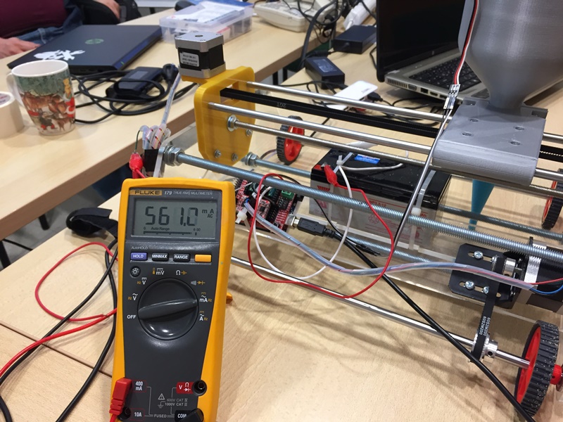
Power = Tension x Current.
P (W)= 12 (V) x 0.561 (A)
P = 6.732 Watts
Files
Click Here to download the eagle file
Click Here to download the board traces
Click Here to download the board drills
Click Here to download the board cutout
Click Here to download the Simple LCD screen code
Click Here to download the LCD Screen with LDR
Click Here to download the Relay with a Push button
Click Here to download the Relay with an LDR and the LCD
Click Here to download the Code with all the connection