Assignment
group assignment:
characterize your lasercutter, making test part(s)
that vary cutting settings and dimensions
individual assignment:
cut something on the vinylcutter
design, lasercut, and document a parametric press-fit construction kit,
accounting for the lasercutter kerf,
which can be assembled in multiple ways
Characterize the lasercutter and making test parts
The machine used: Laser Cutter – Epilog Fusion M2
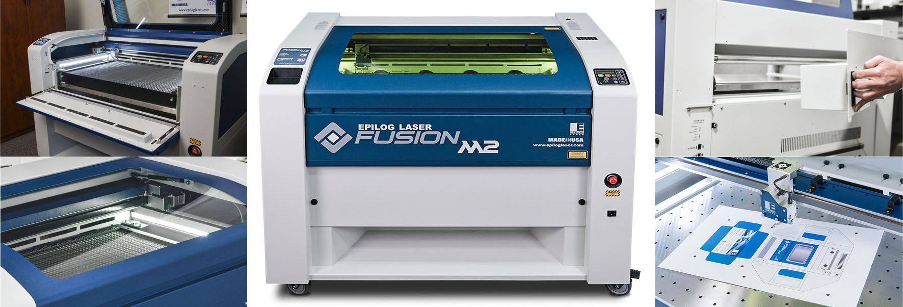
- Work area: 500mm x 800mm
- Materials: wood (12mm), glass, cork, leather, cardboard, paper, fabrics, non-PVC acrylics, and other organic materials (up to 13mm)
- File type: AutoCad, JPG, and BMP for raster.
- Power: 120 Watts
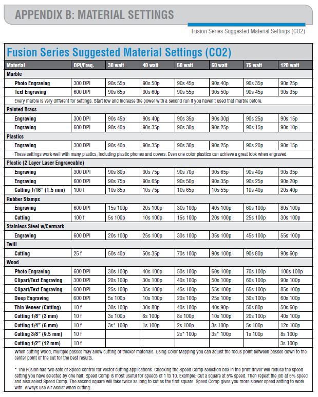
Fusion Series Suggested Material settings for Power, Frequency and Speed:
Material available:
- 3mm MDF -which happened to be of 3.17 mm after measuring it accurately with the calliper
- 5.5 mm MDF
We have used the 3.17mm MDF for the testing
For cutting, the POWER of the laser cutter should always be 100; it varies for engraving.
We calculate the Kerf of our laser cutter via 2 tests:
Kerf is defined as the width of material that is removed by a cutting process. It was originally used to describe how much wood was removed by a saw, because the teeth on a saw are bent to the side, so that they remove more material than the width of the saw blade itself, preventing the blade from getting stuck in the wood.
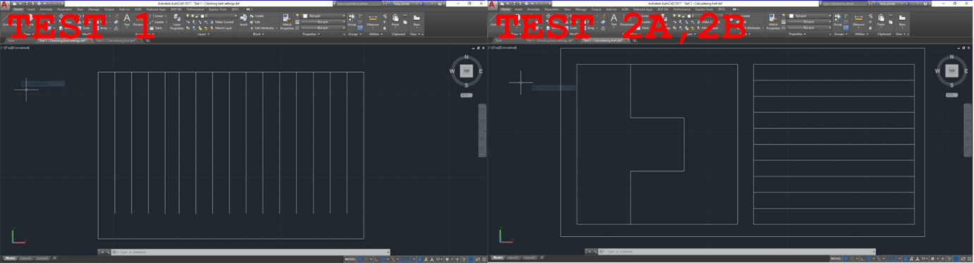
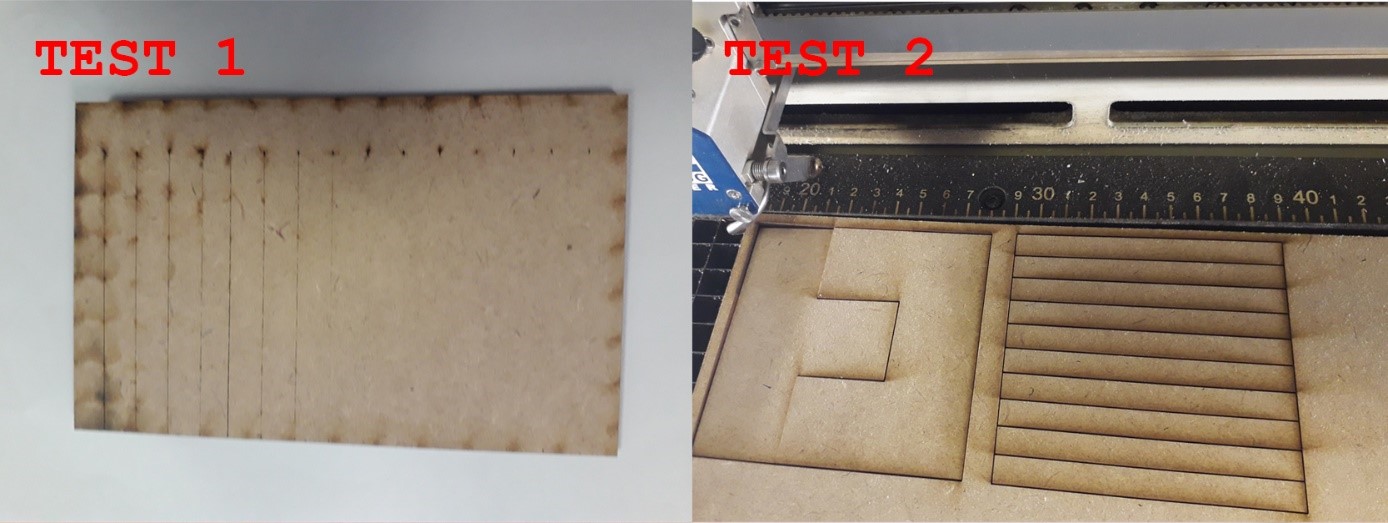
First test:
- Objective: Select the best cutting settings for a specific material in terms of POWER, FREQUENCY, and SPEED . In the case of wood, the FREQUENCY should be the lowest (10).Cutting SPEED needs to be determined in order to have the smallest kerf.
- Method: Cut multiple lines with different SPEED settings around the reference speed provided by the manufacturer’s specifications. Observe by eye at which speed the material is fully cut. The first fully cut line should be the finest cut, thus the smallest kerf.
Second test:
- Objective: Measure the kerf for the setting previously selected
- Method: Cut one or multiple segments with the same setting. Measure the length of the outer frame, measure the length of the adjacent cut segments, divide the difference by the number of cuts. The result is an estimation of the kerf. We made two tests with different layouts to get an average.
How to perform the tests:
- First: Drawing a test layout.
- Draw a layout on a vector type CAD (we used AutoCAD). Make sure there is no line superposition to avoid cutting the same line twice. The lines that should be cut in a single cut with same parameter should be joined into one line. (Click ‘Ctrl + A’ then ‘Join’)
- Save as DXF 2007
- Import DXF file in Corel Draw. Make sure all the lines are hairline (hairline will be cut; other lines will be engraved). Place the drawing in top left corner.
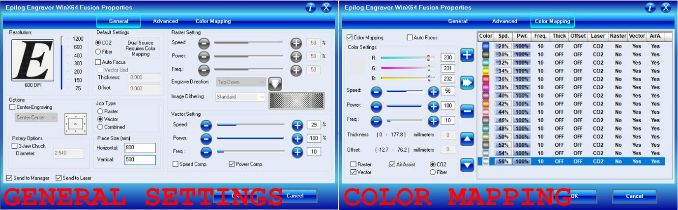
- Open the laser cutter properties window (Ctrl + P for printing the job). In the general tab select vector job type, in the layout tab select top left corner for positioning, enter machine bed dimensions (800x500 mm for our machine)
- Second: Colour mapping (for Test 1 only):
- Colour mapping helps in feeding different settings for each different line, so that the laser cutter understands that it should not cut all the lines in the same way or speed
- In Corel Draw, colour each line with a different colour and note the RGB of each colour.
- In the laser cuter properties window, open the colour mapping tab, copy the RGB previously noted and assign cutting parameters for each colour, specifying speed, power, and frequency (in %).
- For wood, the power will remain at 100%, and the frequency at 10% according to the manufacturer’s specifications. So in this case only speed will vary.
- According to manufacturer’s specification, the reference speed value for wood is 40%. So the speed setting will have to range around this value.
- Select vector and deselect raster to cut and not engrave (it shouldn’t make a difference if all the lines are hairlines).
- Third: Operating the laser cutter.
- Turn on the machine, then load the file to the laser cutter by clicking print. From there, the work is on the laser cutter interface.
- Position the wood board on the laser cutter metal bed. Then place the gage tool to calibrate the focal point of the laser on the right Z value. When the gage touches the board, zero Z. Then move the laser cutter head to the starting position and zero XY
- Before starting, make sure that the compressor is turned on, as well as the extractor, to enable air flow to evacuate the fumes and prevent fire risks and toxic fumes inhalations.
- Start cutting, and supervise the machine till the job is completed (the laser cutter should not be left without supervision while operating).
- Once the job is done, wait for fumes to be fully evacuated before removing the board.
Test results:
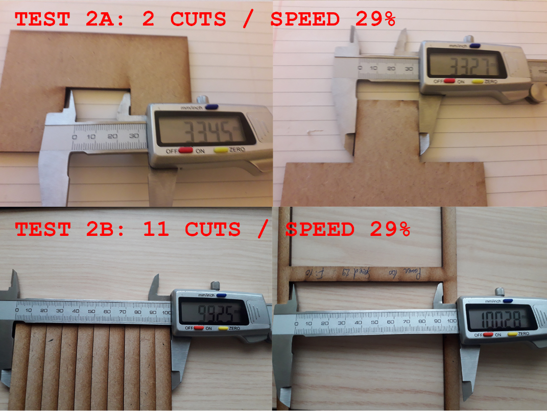
- First test: The best cut appears to be between 28 and 30% speed
- Second test: I- Evaluation of the kerf for speed 29%
a. Test 2A: Kerf = (33.45 - 33.27) / 2 = 0.090
b. Test 2B: Kerf = (100.28 - 99.25) / 11 = 0.094
 II- Evaluation of the kerf for speed 30%
a. Test 2A: Kerf = (33.81 – 33.73) / 2 = 0.04
b. Test 2B: Kerf = (100.34 – 99.88) / 11 = 0.042
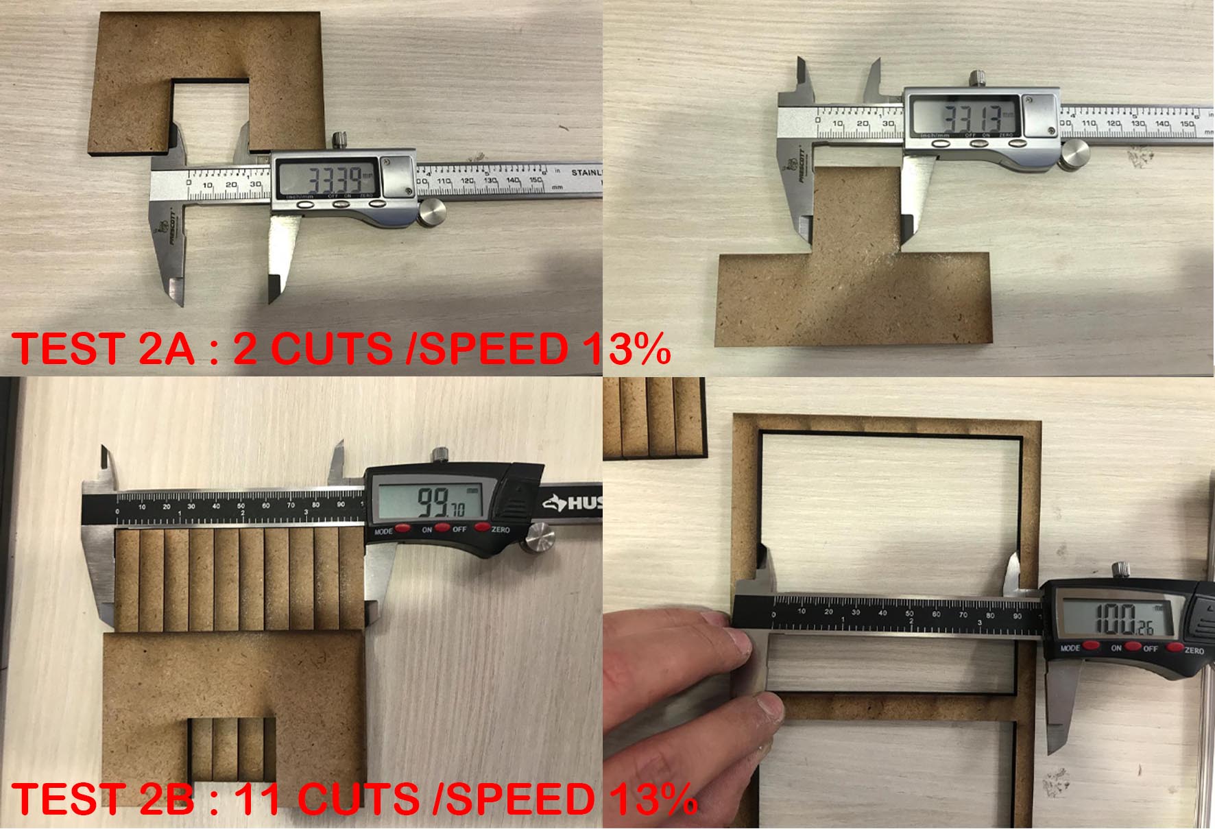
Test results 5.5mm:
- First test: The best cut appears to be between 13% speed
- Second test: I- Evaluation of the kerf for speed 13%
a. Test 2A: Kerf = (33.39 - 33.13) / 2 = 0.13
b. Test 2B: Kerf = (99.90 - 99.40) / 11 = 0.05
Design a press-fit construction kit
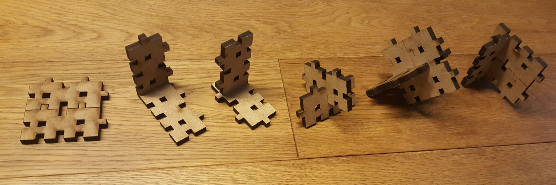
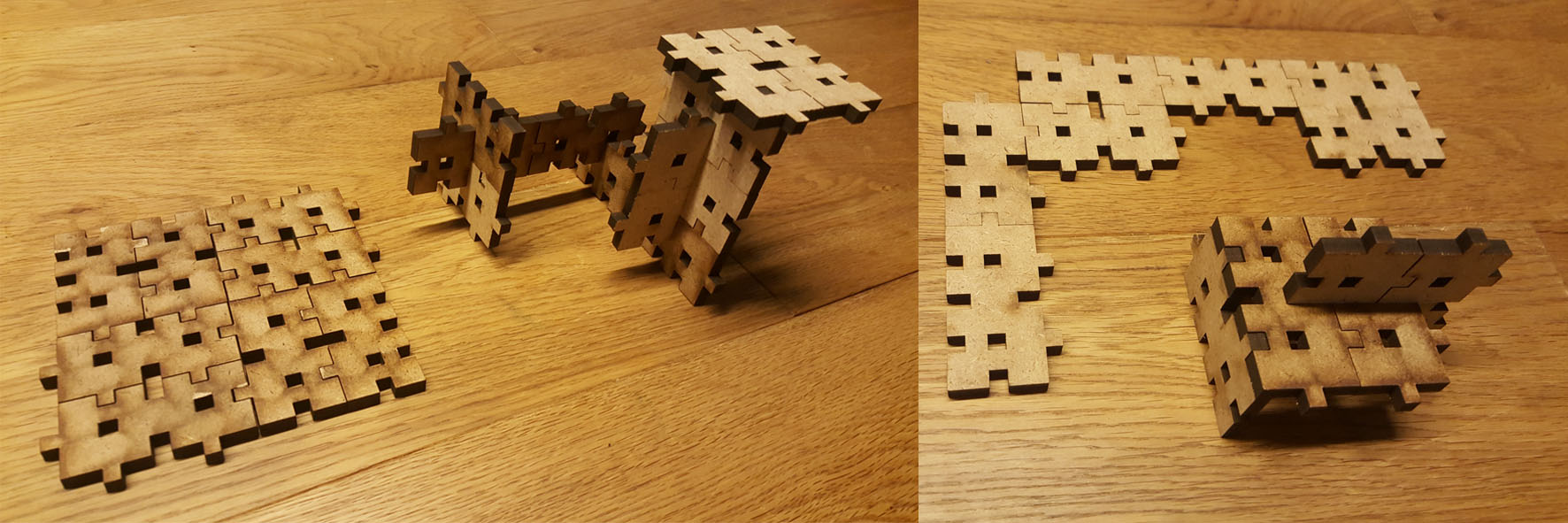
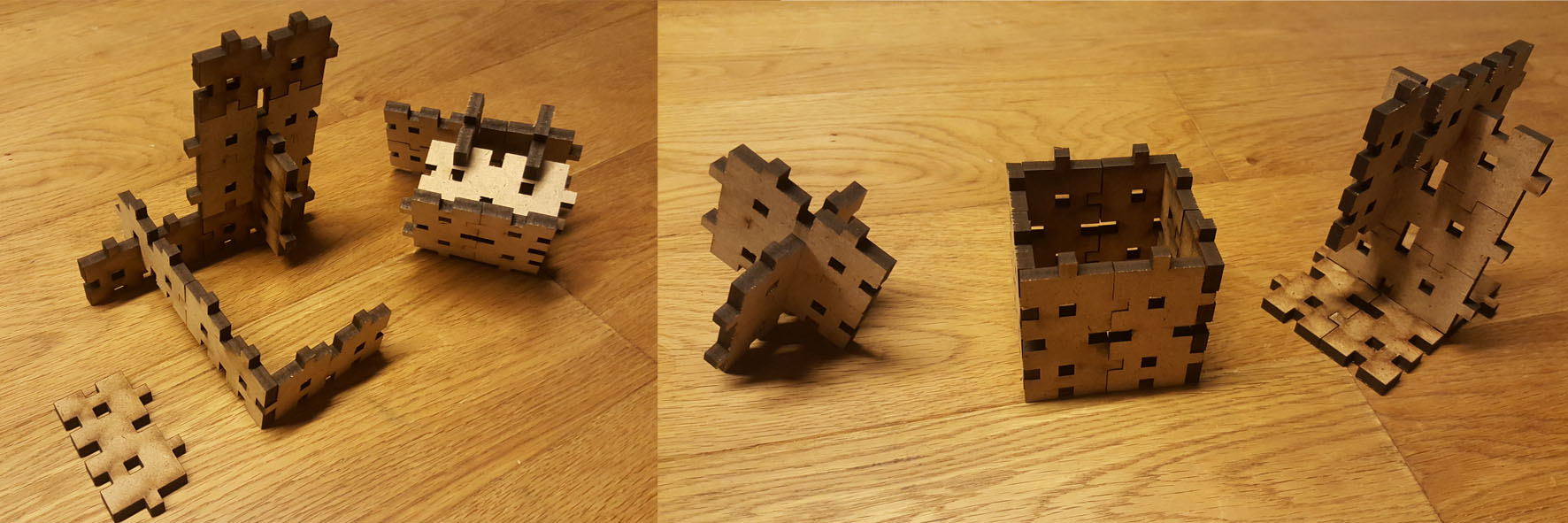
In this assignment I wanted to create only ONE PIECE that can be PRESS-FIT in a 2D PLANE to create multiple PATTERNS, and PRESS-FIT in 3D SPACE to create multiple GEOMETRY.
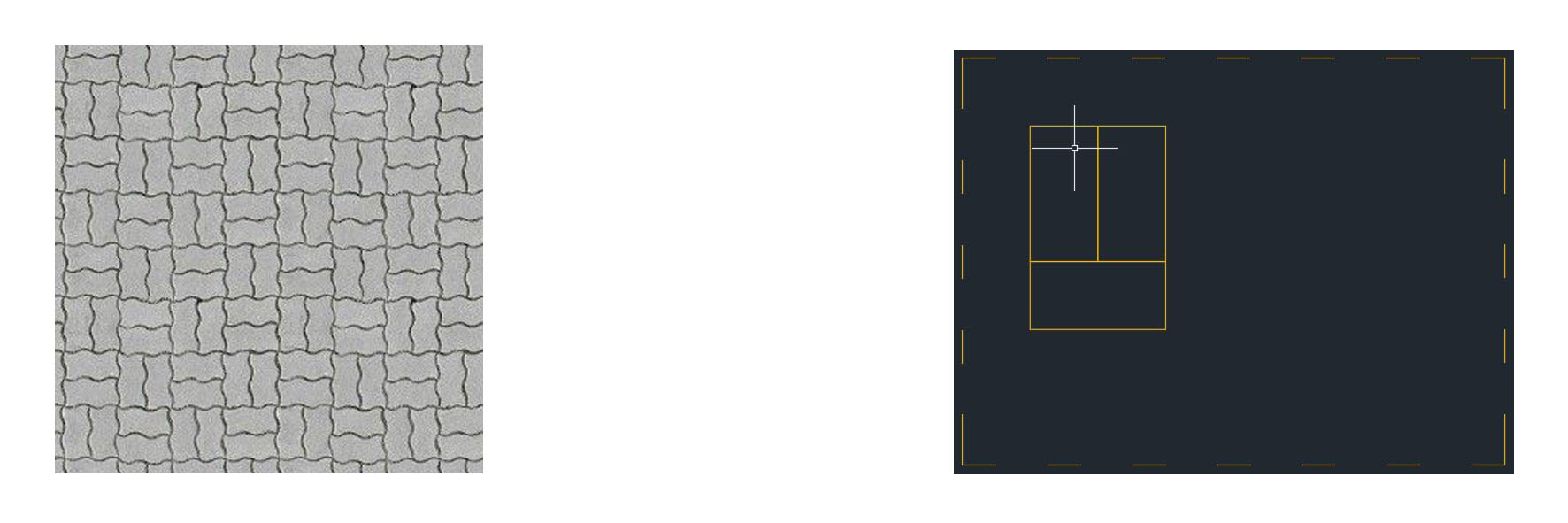
For that I will start sketching in Autocad a basic rectangular shape that has as length the double of it's width (e.g.: domino pieces)
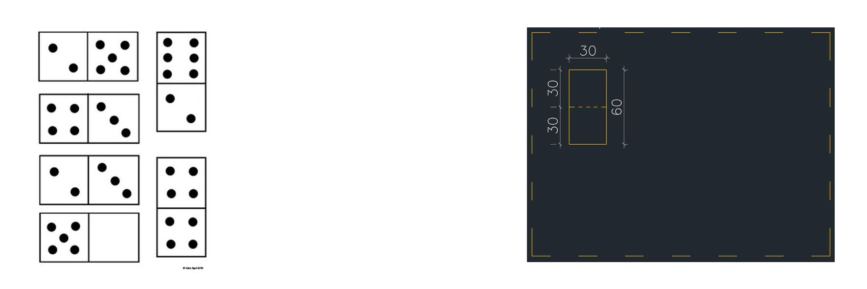 These two rectangles put together should be locked by placing a third rectangle next to them with an opposite direction (e.g.:interlocked pavement)
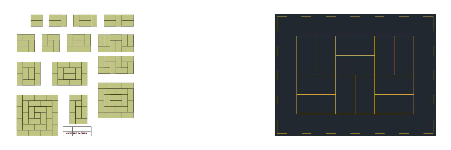
 If I continue with same idea of interlock geometry I will have the following pattern (e.g.: tatami)
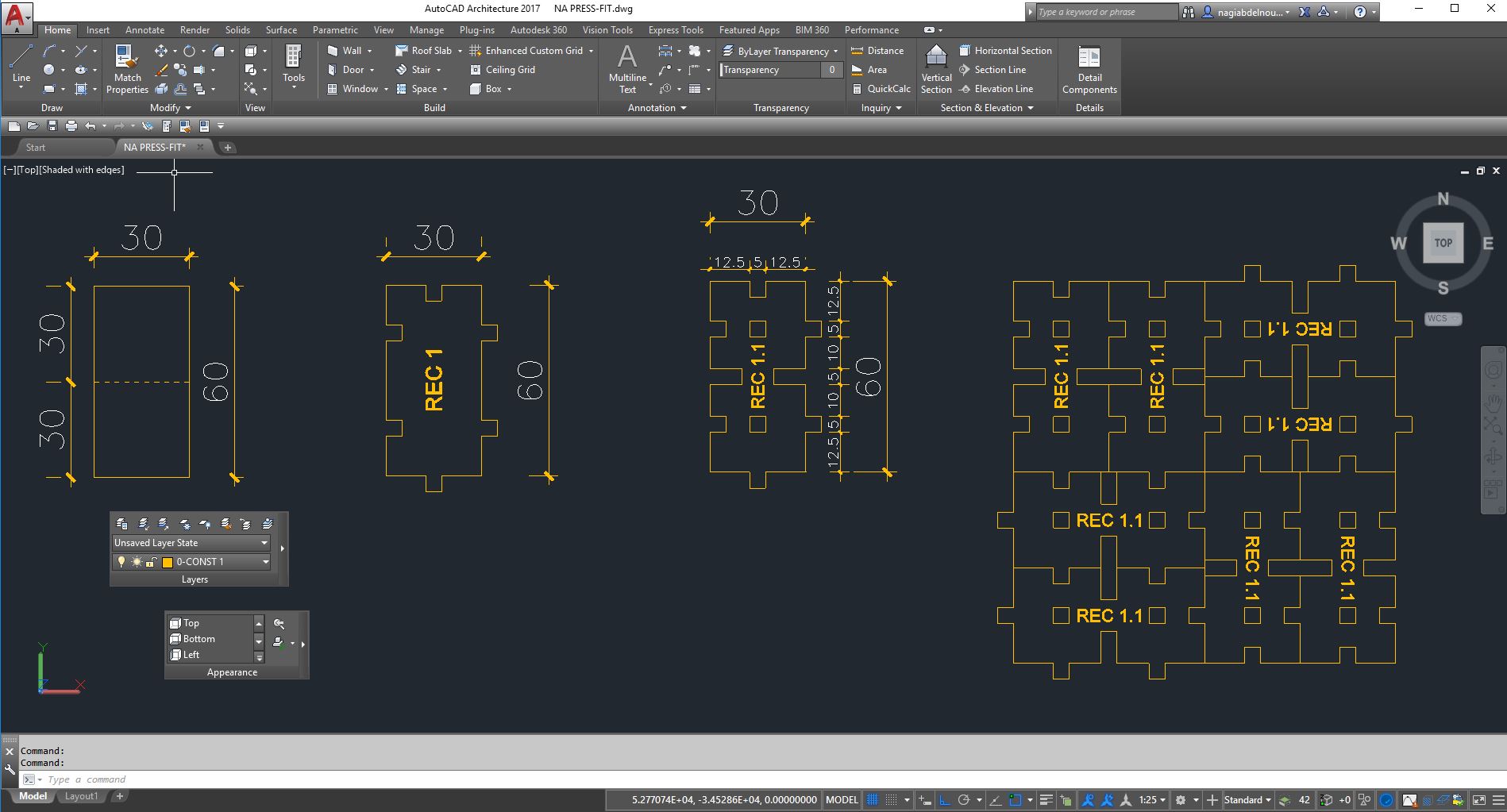
 Now I will convert the rectangle into an Autocad block (in order to modify it later as mush as I want) and add the needed geometry to make them press-fit together.
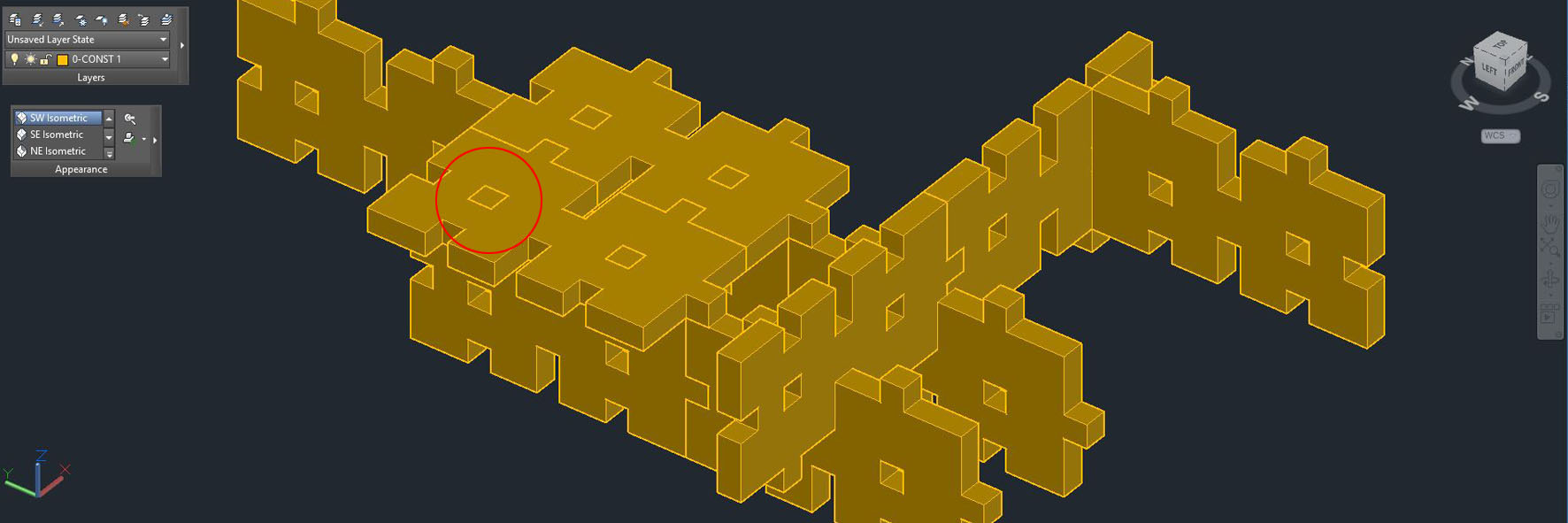
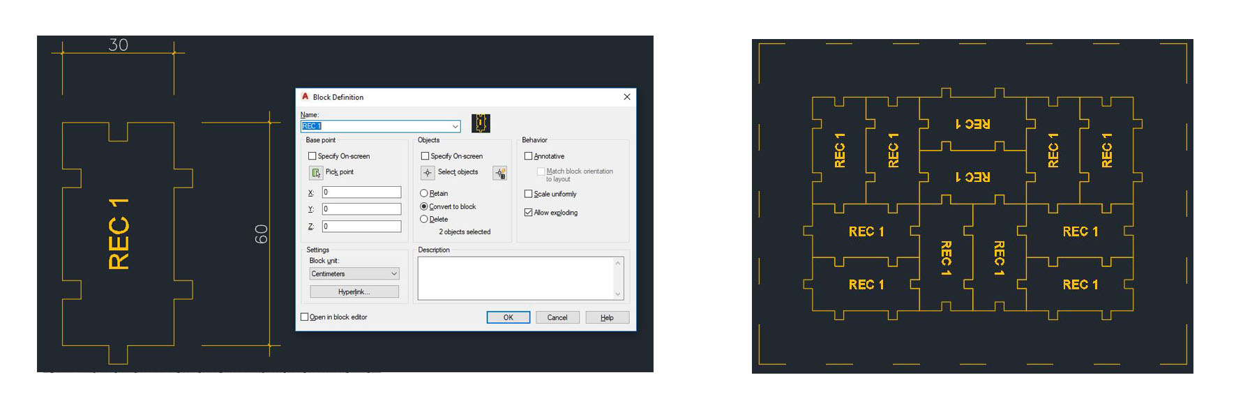 After trying to press-fit my pieces in a 2D plane and it's potential pattern, I will extrude it and test the geometry in 3D.
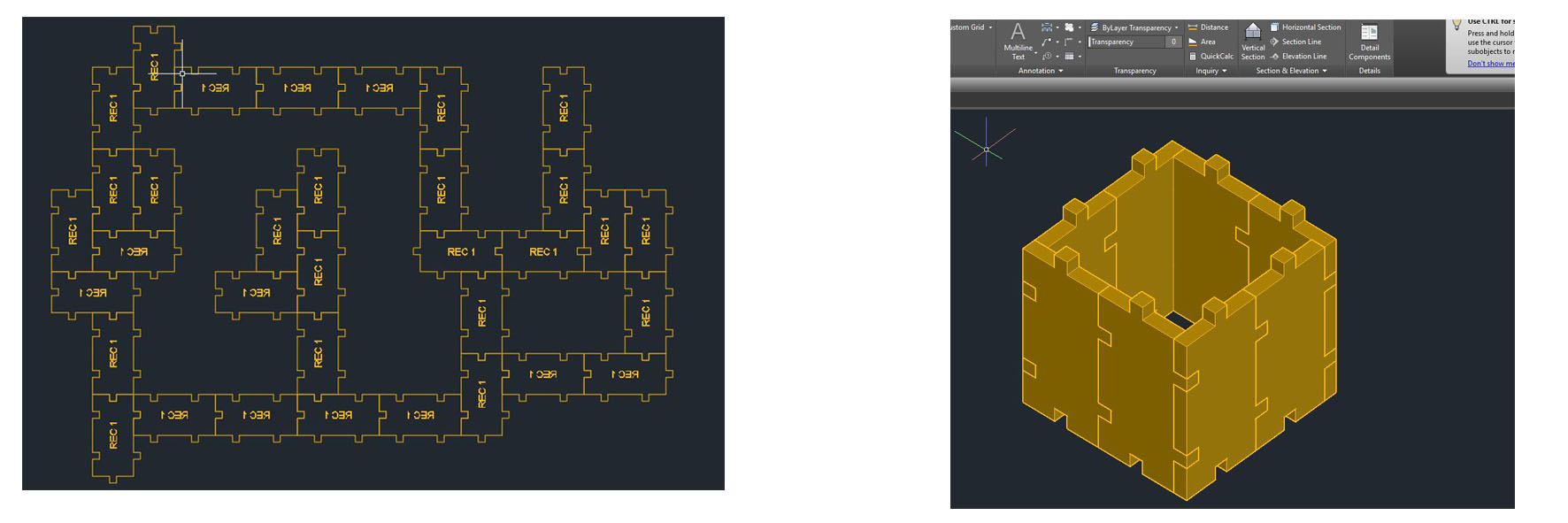 I will add some grooves to my block in order to have more potential 3D fixation.
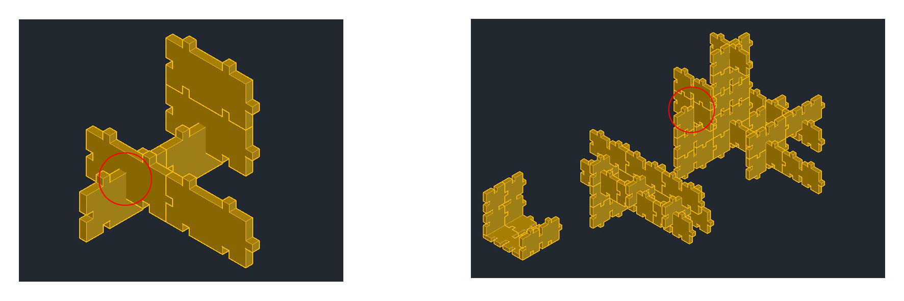 And add some more voids for more options.
 Now that I am satisfied with my testing and result in Autocad, I will recreate my block parametrically in Fusion software taking into account the lasercutter kerf.
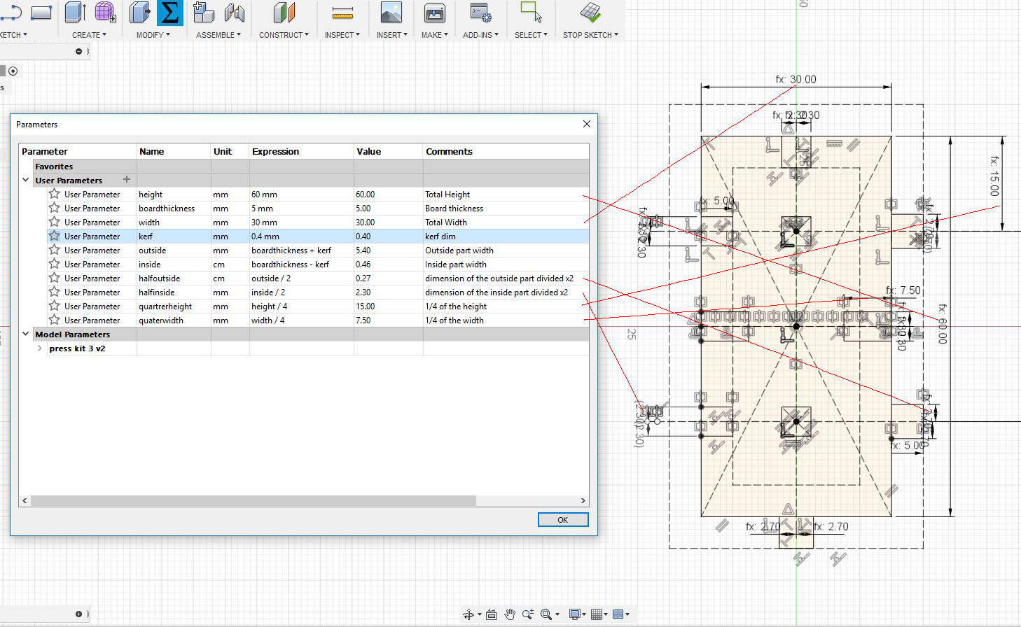
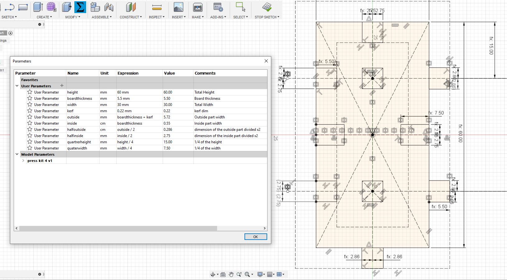
 In Fusion I will start by adjusting the unit to mm and adding the parameters I will use. Than I will draw my center rectangle starting from the origin than set an outside offset and an inside offset with value equal to the boardthickness parameter. I set these offset as construction line (dotted lines in the image)
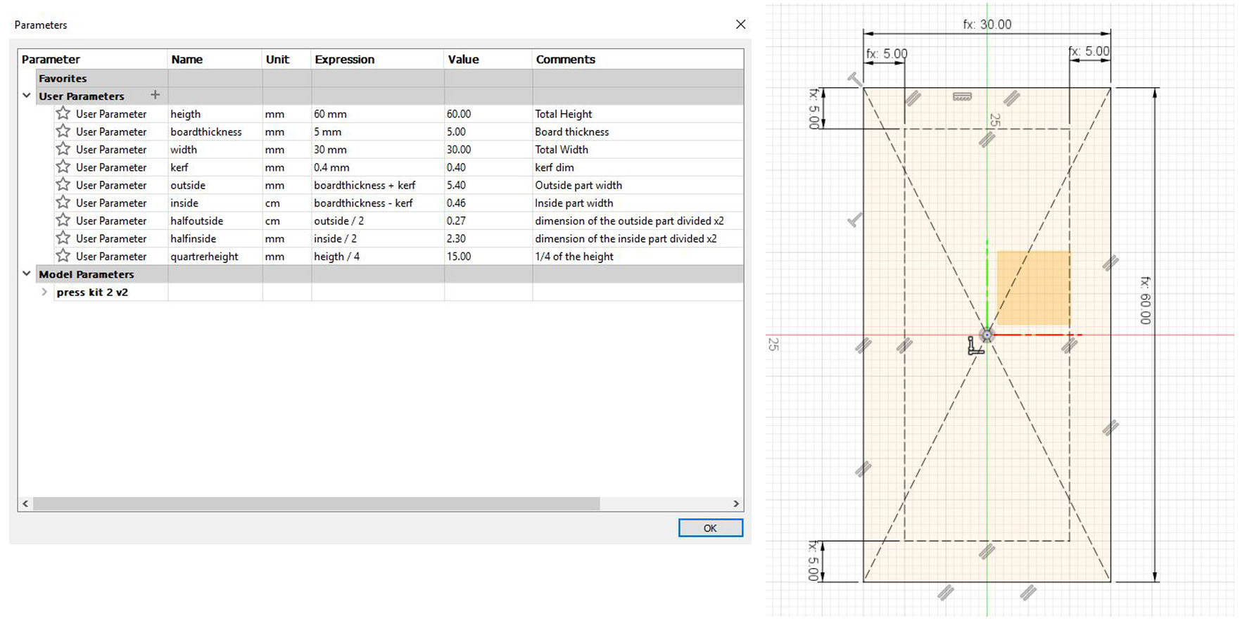 Then I will start drawing my inside grooves and outside elements and give each line a specific dimension parameter already set in the beginning.
 I will use mirror command for the identical forms and use colinear constraint for the lines I want to link together.
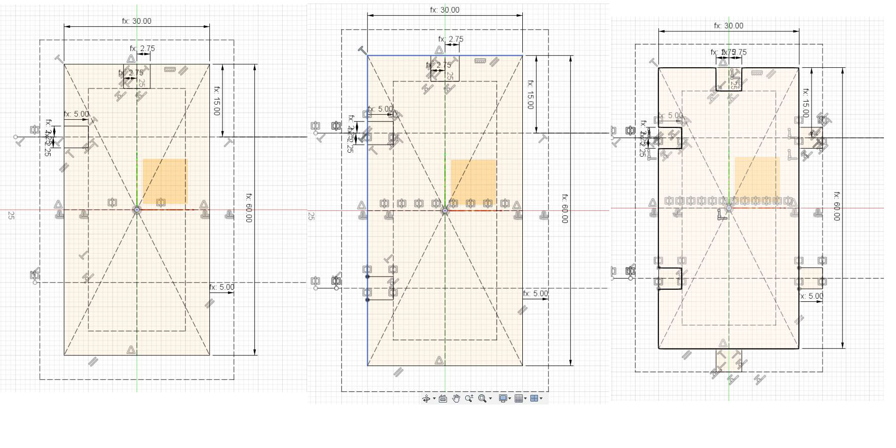
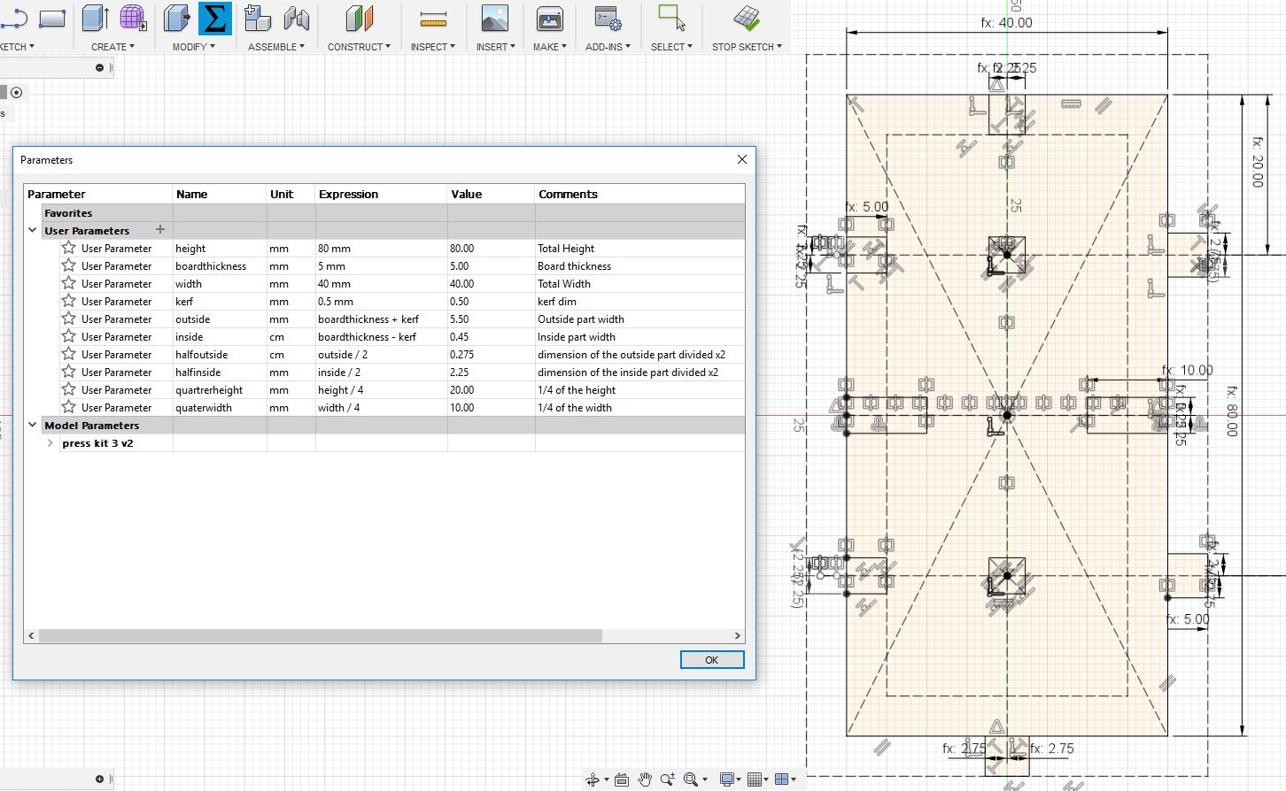
 At each step I try to change some parameter to test if everything is working fine. Below is the same model with different parameters.
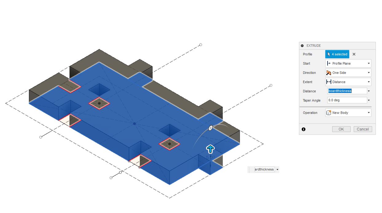
 After that I press / pull my sketch to transform it into a 3D body with distance equal to the boardthickness parameter.
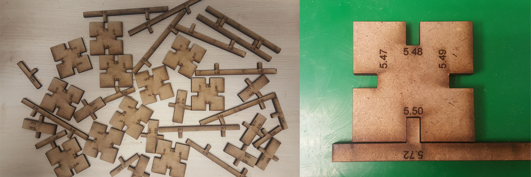
 My final pieces will be laser cut in a 5.5mm MDF wood board. And after several testing for the inside and outside joints dimension, it turned out that the 5.5mm dimension for the inside part fits well with the 5.72mm dimension of the outside one (because of the kerf of course,below are the testing parts).
 I will adjust my parametric sketch according to the tests results and export it to DXF format.
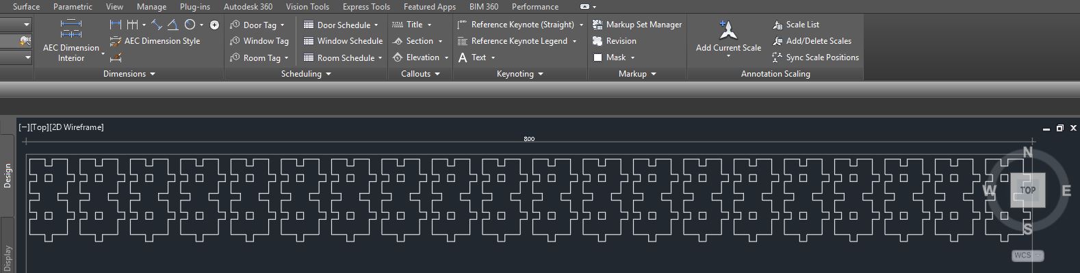
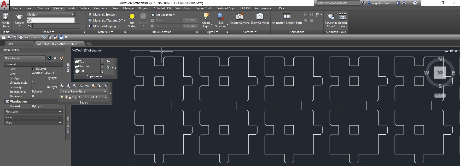
 Then will open it in Autocad, adjust the final layout and send it for cutting.
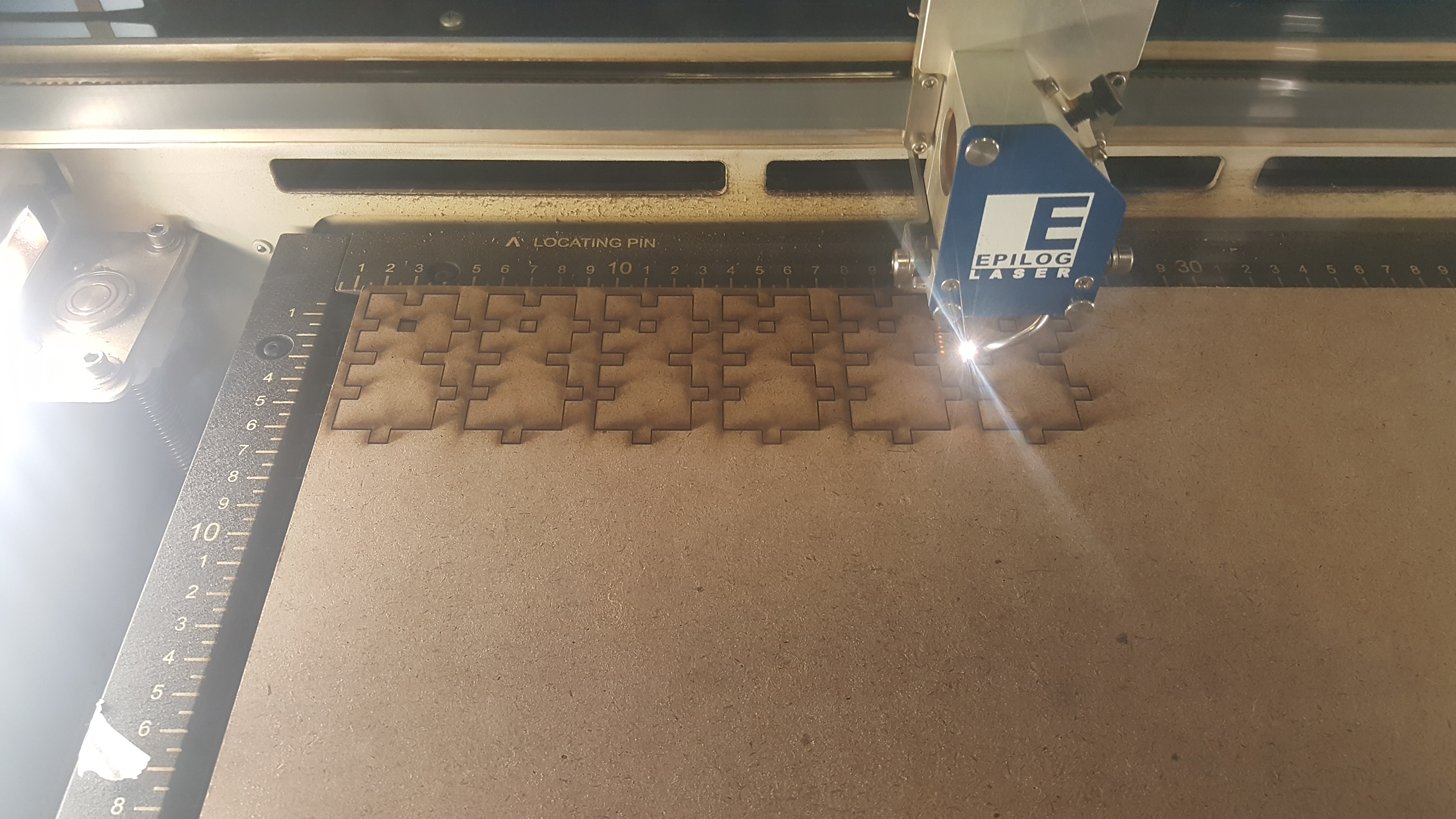
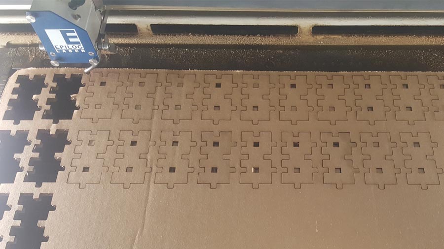
 Cutting in progress...
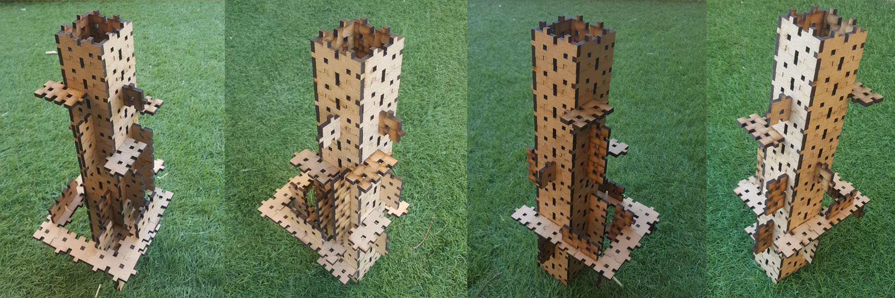
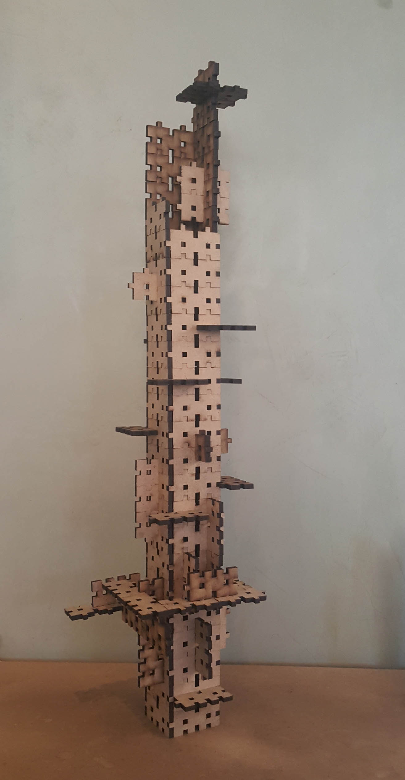
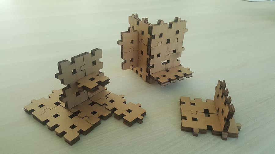
 ...And the final pieces.
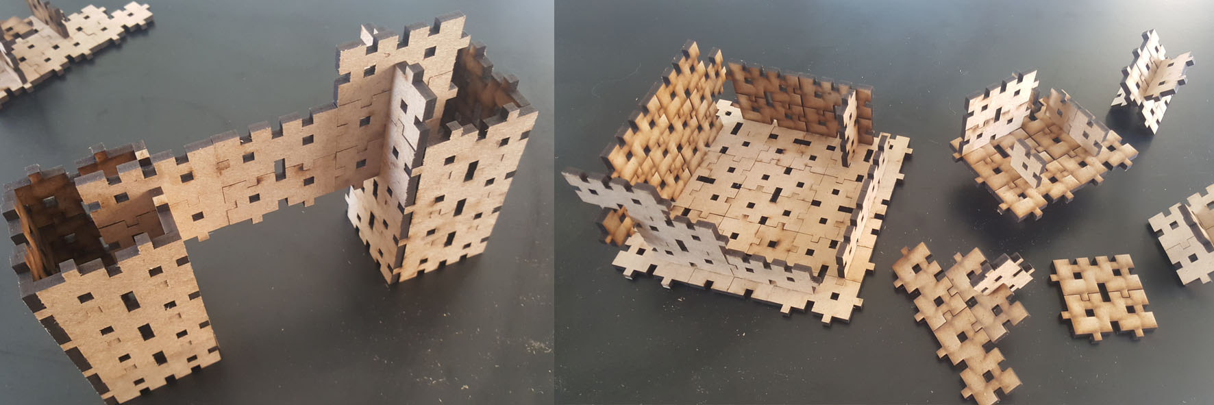 It can be also a prefabricated concrete element for a tower building...
Same design using cardboard
Now I will test the previous design using cardboard , for that I will add chamfer to the edges because cardboard are more flexible than the mdf and it will be easier to press fit them without distroying the edges
And these are the settings used
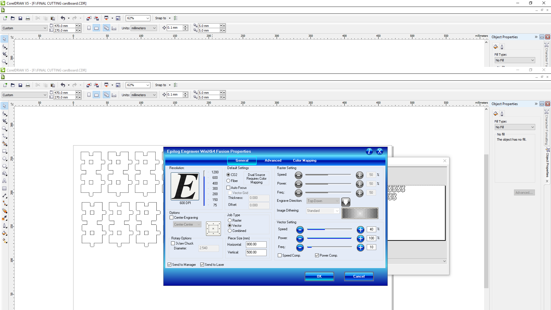
Below is the cutting
And this is the final result
After using MDF and Cardboard, I can note the following difference between these two materials:
- The cardboard is cleaner, we have less burnings around the cutting and less smell.
- In cardboard we need to chamfer the edges in order to easily press fit them without destroying the edeges because this material is softer than the MDF. With the MDF I press fit them easily without chamfer.
- Mdf is a stronger material than the cardboard and I can do bigger objects with it.
- Carboard is a lighter material than the MDF and can achive lighter final objects with it.
- Both materials are nice to work with so the choice between them will depend on the final object size and usage.
Cutting on the vinylcutter
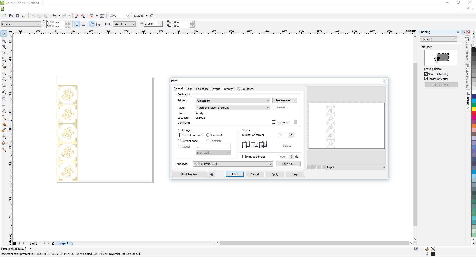
I will start with my logo on Autocad, adjust it and give it some colors similar to the FabAcademy one.
![]() After several essays I have chosen a design and added an alignment contour including the different color used. This will make it easier for me to align them when sticking them after cutting .(the orange lines are just construction lines for the solid hatch).
After several essays I have chosen a design and added an alignment contour including the different color used. This will make it easier for me to align them when sticking them after cutting .(the orange lines are just construction lines for the solid hatch).
![]() Now I will separate the colors to prepare them for cutting.
Now I will separate the colors to prepare them for cutting.
![]() Than right-click on the hatch and generate boundary.
Than right-click on the hatch and generate boundary.
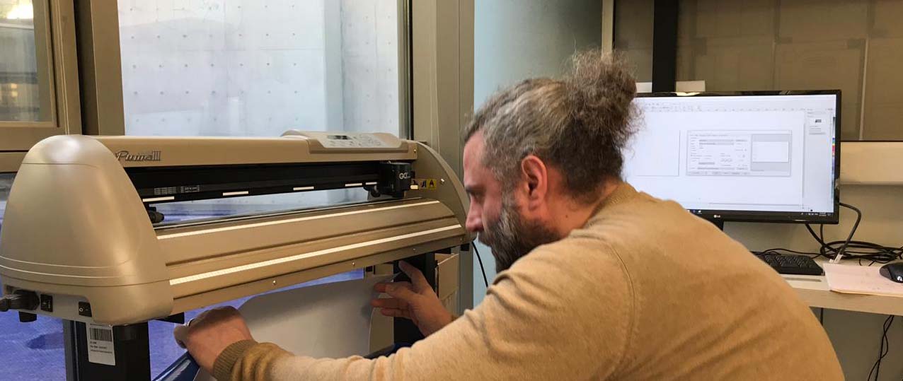
![]() Setting the vinyl cutter roll.
Setting the vinyl cutter roll.
 Now I will open each color file on Corel draw and set all the lines as Hairlines and click print to cut each color alone.
 After cutting I realized that the starting point of the cutting line is not very clean, so I decided to extend the starting point of each polyline in Autocad outside the final needed vinyl to have cleaner angles.
![]() And added some separations in the unneeded vinyl parts to make it easier to remove.
And added some separations in the unneeded vinyl parts to make it easier to remove.
![]() This is the new result after cutting.
This is the new result after cutting.
After this I reput all the colors on a same transparant adhesive film in order to stick them on the final destination.
![]() And this is the logo on the back of my laptop.
And this is the logo on the back of my laptop.
![]()
Summary
For my press-fit kit I have used Autocad for the design and sketch, then used Fusion to transform the sketch into a parametric one in order to change the different dimensions whenever I want, taking into account the kerf and the cutting tests results.
For my vinyl cutting I have completed the design on Autocad with 4 different colors, then separated the colors, created a boundary for each one with a reference line in order to realign them after cutting and before the final sticking.
Files
Click Here to download all the Design Files