
6/2/2019
Characterize your laser cutter, making test part(s) that vary cutting settings and dimensions
Cut something on the vinyl cutter design, lasercut, and document a parametric press-fit construction kit, accounting for the laser cutter kerf, which can be assembled in multiple ways
Materials available:
We have used the 3.17 mm MDF
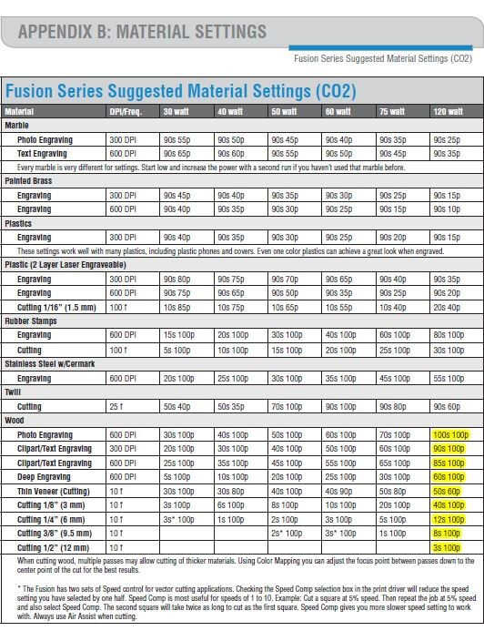
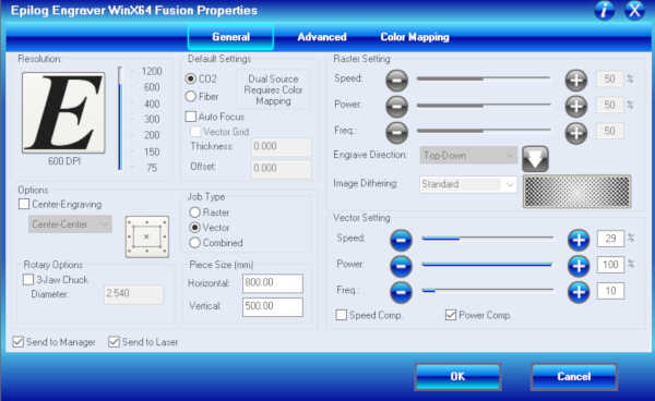
For cutting, the power of the laser cutter should always be 100; it varies for engraving
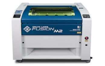
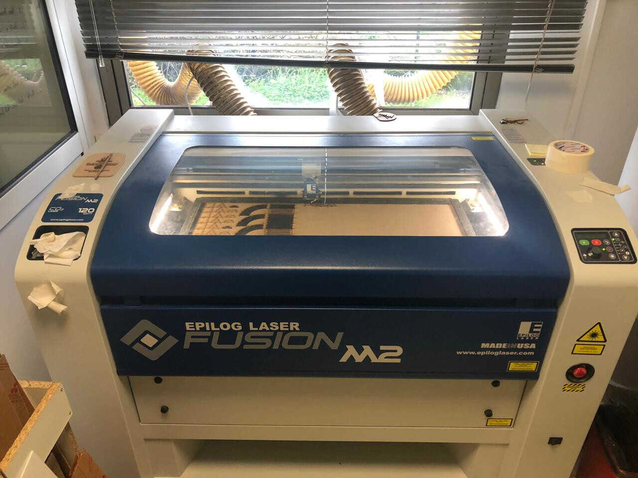
Machine used: Laser Cutter – Epilog Fusion M2
Fusion Series Suggested Material settings for Speed, Power and Frequency
We calculated the kerf of our laser cutter via two types of tests:
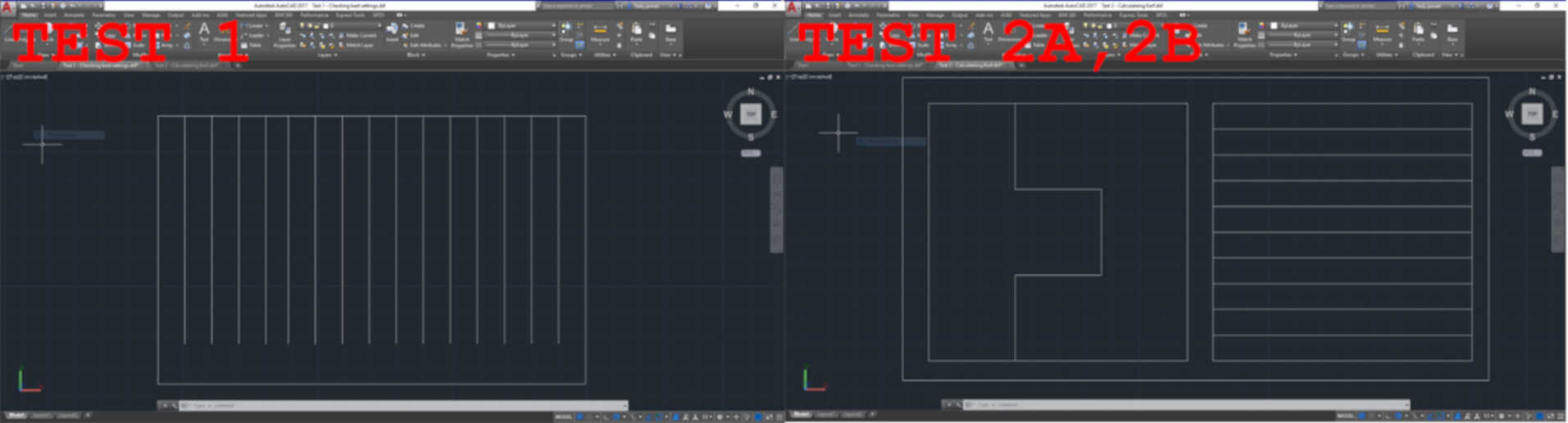
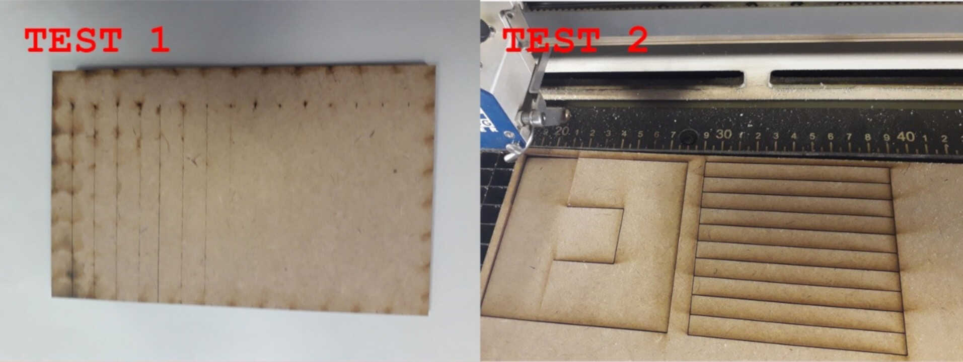
1) First Test:
Objective: Select the best cutting settings in terms of speed, power, and frequency. In the case of wood, the frequency should be the lowest (10). Cutting speed needs to be determined in order to have the smallest kerf.
Method: Cut multiple lines with different speed settings around the reference speed provided by the manufacturer’s specifications. Observe by eye at which speed the material is fully cut. The first fully cut line should be the finest cut, thus the smallest kerf.
1) Second Test:
Objective: Measure the kerf for the setting previously selected.
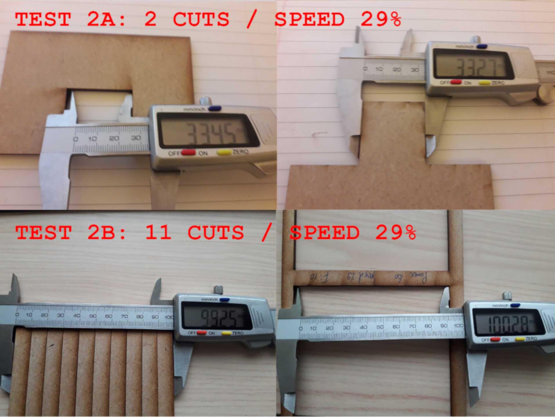
Method: Cut one or multiple segments with the same setting. Measure the length of the outer frame, measure the length of the adjacent cut segments, divide the difference by the number of cuts. The result is an estimation of the kerf. We made two tests with different layouts to get an average.
How to apply tests
1) First: Drawing a test layout
2) Second: Colour mapping (for Test 1 only):
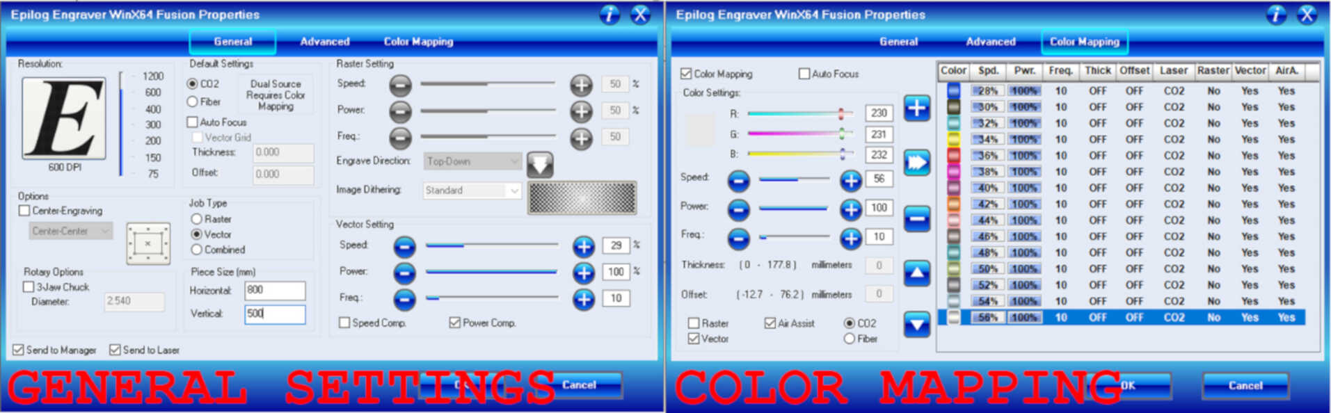
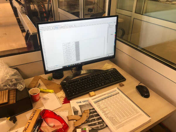
3) Third: Operating the laser cutter.
TEST RESULTS
1) First test: The best cut appears to be between 28 and 30% speed
2) Second test:
i) Evaluation of the kerf for speed 29%
i) Evaluation of the kerf for speed 30%
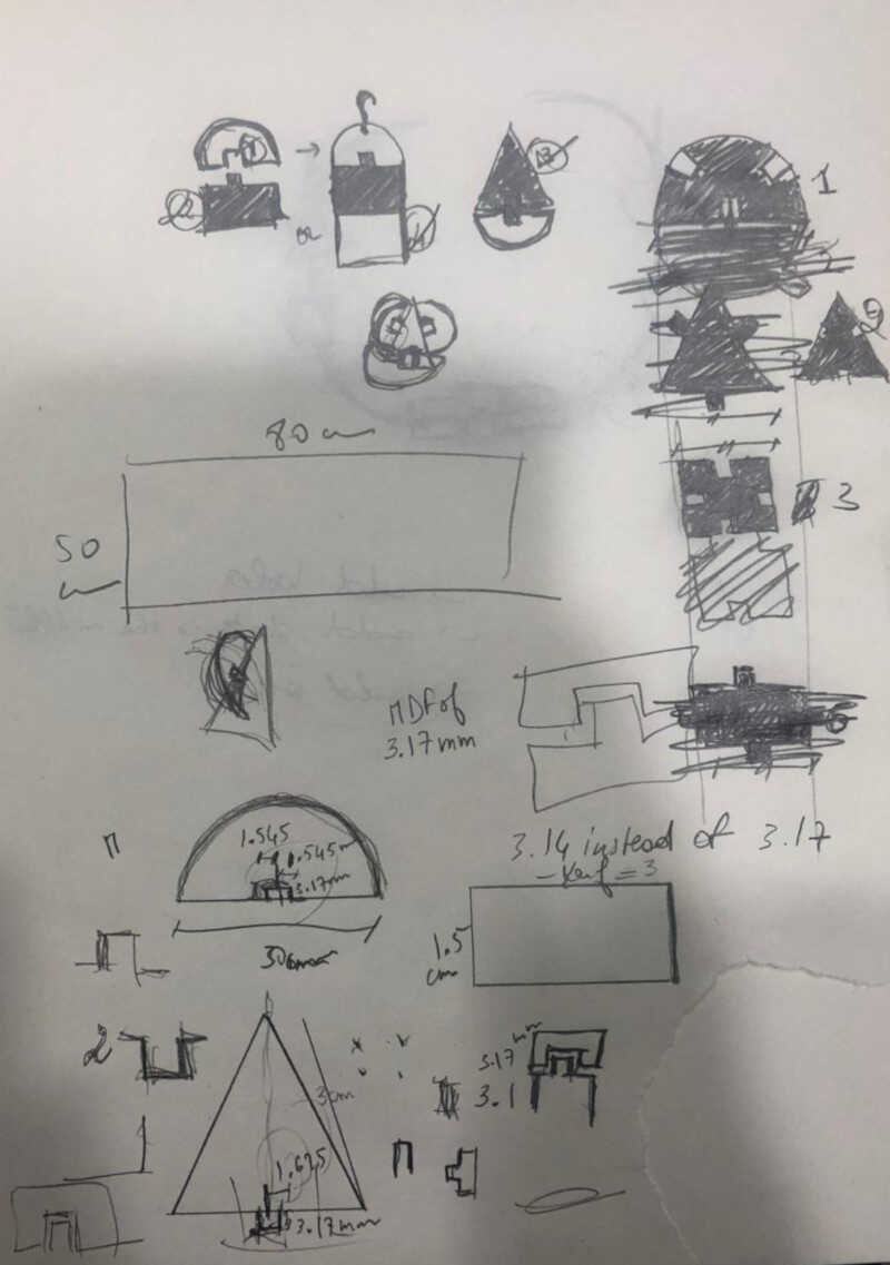
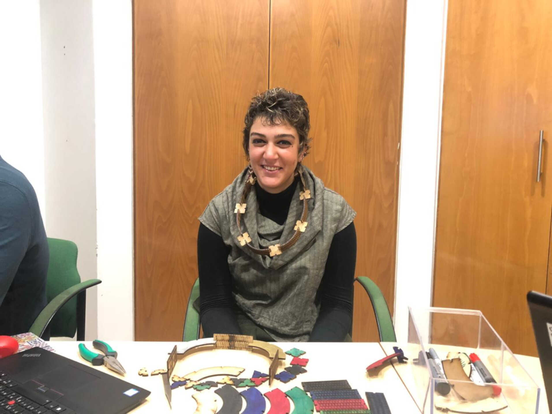
I wanted to make some accessories that I can wear especially that I am fashion driven so I was trying to really enjoy this assignment
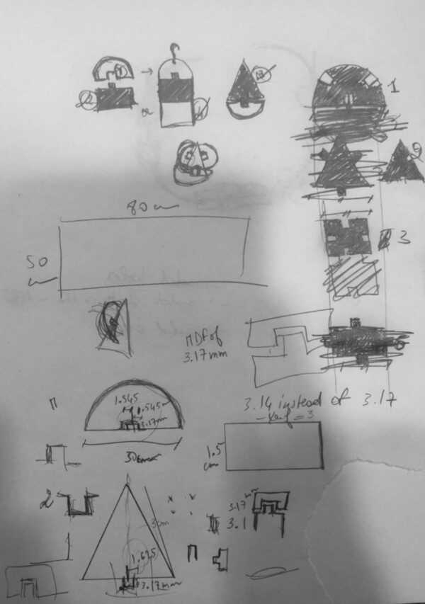
I did not have previous experience with Fusion360 in order to draw a parametric design. So I thought of keeping it simple while being inspired by the Bauhaus and De Stijl movement and use basic geometrical shapes: a square, a triangle and half of a cercle.
I have also added a curve so that it can help me in designing my necklaces.
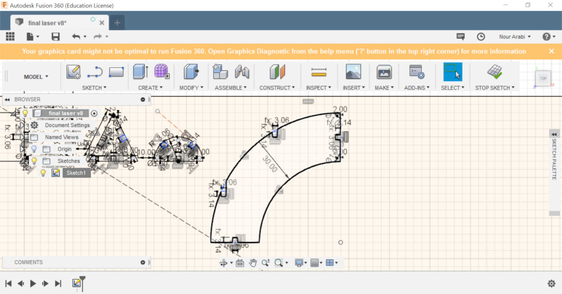
Then I started to draw my basic shapes on Fusion360, while keeping them all as one sketch so I can save the whole drawing as one DXF file for the laser cutter
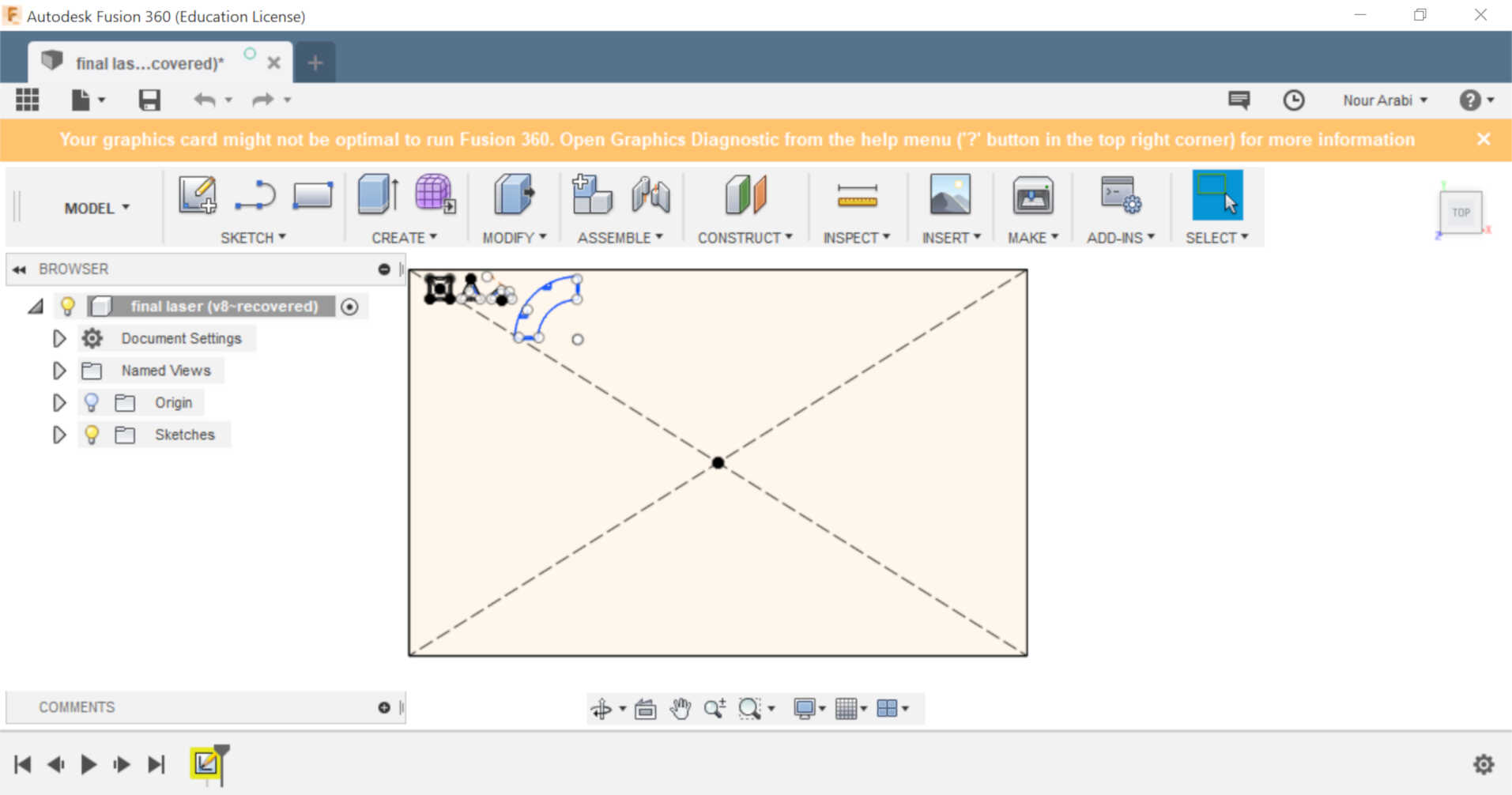
A square of 30x30 mm, a triangle of 30mm base and half a cercle of 30 mm diameter
In order to draw those shapes, I used basic commands such as a 2 point rectangle and center diameter and line
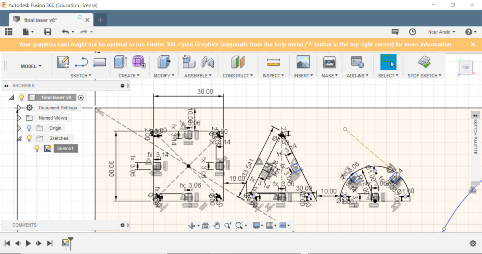
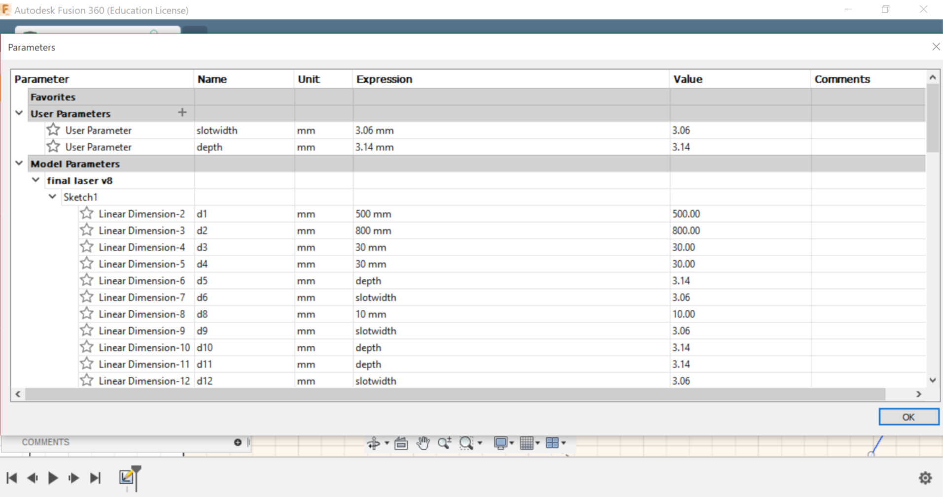
I needed then to add my slots for the press-fit kit and which need to be parametric. So I had two parameters in my fusion file: the slot width and the slot depth. The slot width was calculated according to the kerf of 0.04 for the speed of 30. So the width of my slot needs to be 3.06 mm. I wanted to keep the depth of the sloth pretty close to the thickness of the MDF I have used and which is 3.17 or 3.14 mm.
My curve was based on a cercle of 80 mm diameter so it can easily fit as a necklace around the neck
I have then saved the sketch as DXF
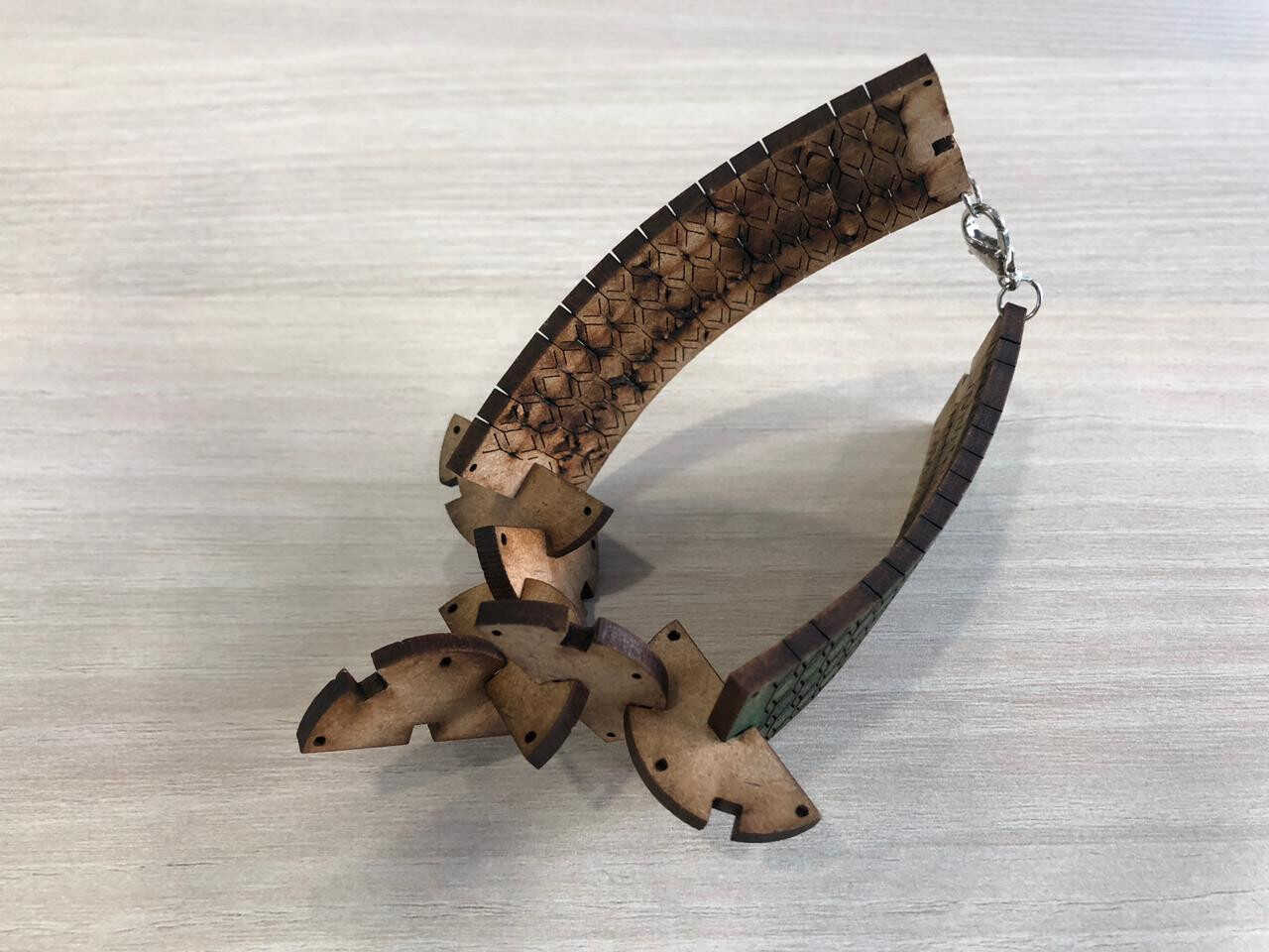
The living hinges were very interesting to me so I thought of adding them to my design, especially that they can be easily used as bracelets and as parts of the necklaces
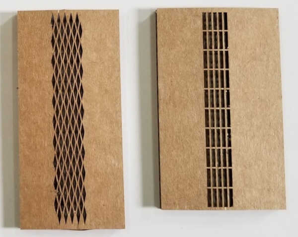
You can easily download some flexible hinges patterns from Instructables website or just click here
I have scaled the chosen pattern needed and added it to my DXF file and saved it
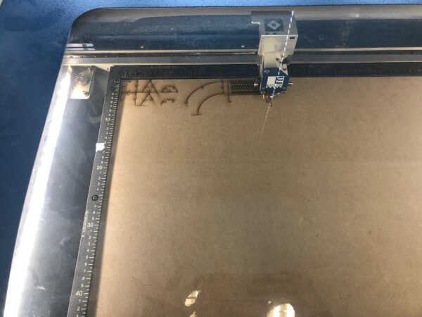
Time to print. The file was imported to Corel Draw, and the speed used is 30
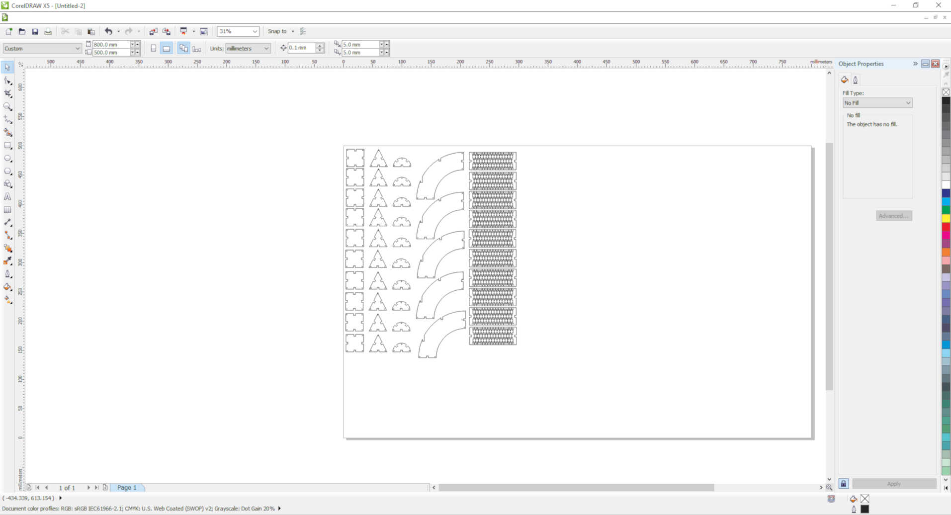
Make sure that your drawings are positioned on the top left corner of your sheet layout
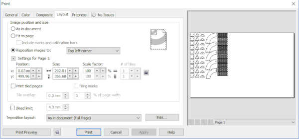
Set the Z axis to 0 and move the X and Y accordingly and set them. Then make sure before printing your job that the fume extractor and air compressor are on
In case of fire or anything else that is not working well, press the emergency stop button
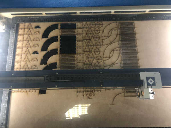
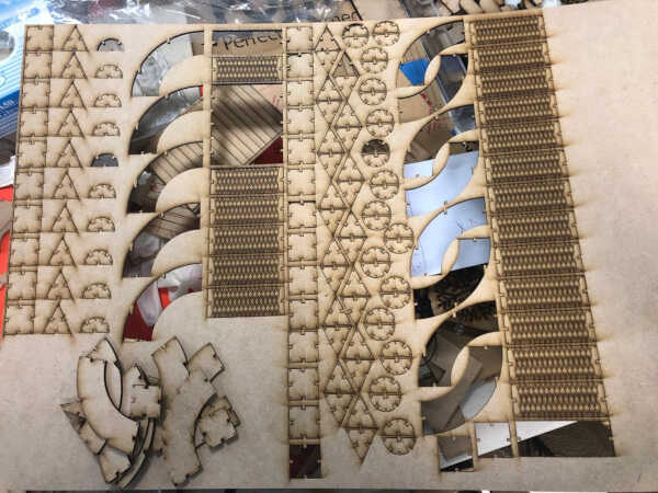
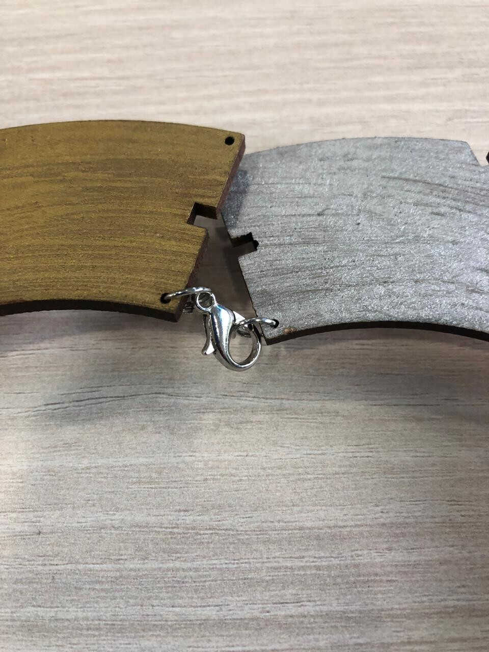
And the job is being printed and it took 38 min. With a speed of 30, the pieces were not coming out easily off the MDF board so I changed it to 29. The layout of the pieces was also changed on Corel Draw in order to minimize the waste of material as much as possible -so more parts were added and were much closer to each other
You can see both speed trials in the below photos
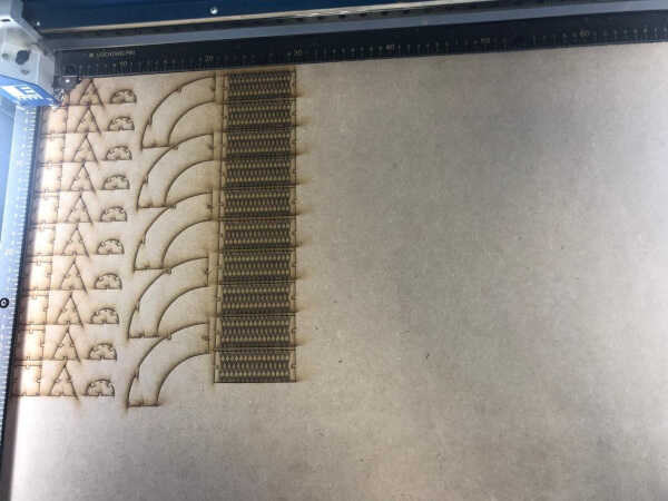
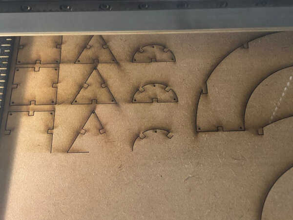
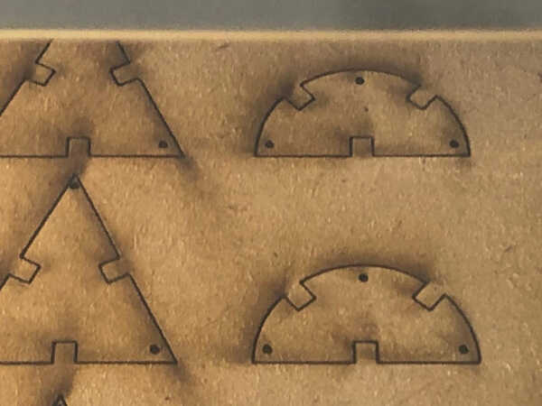
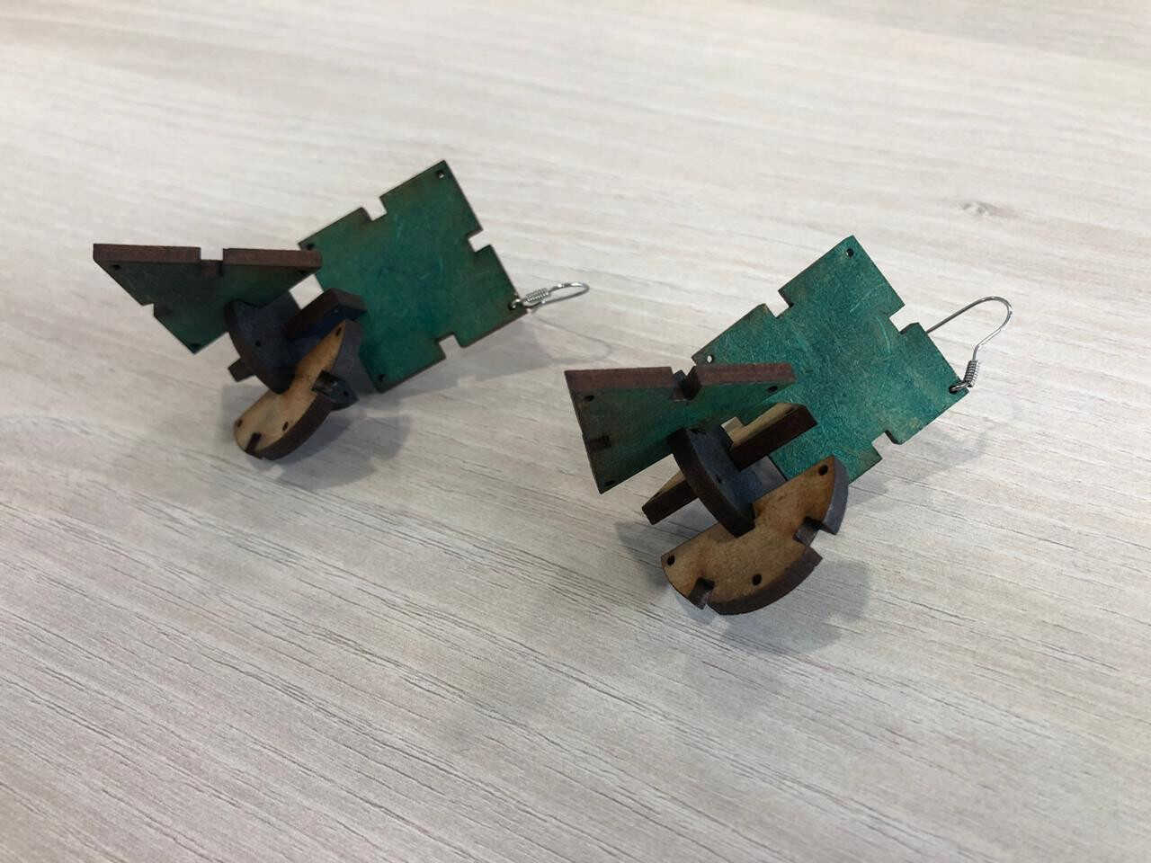
You can also see that I have put some holes of 1 mm for inserting the wire of the earrings or the rings for the necklaces
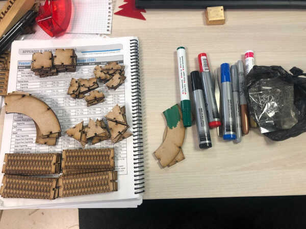
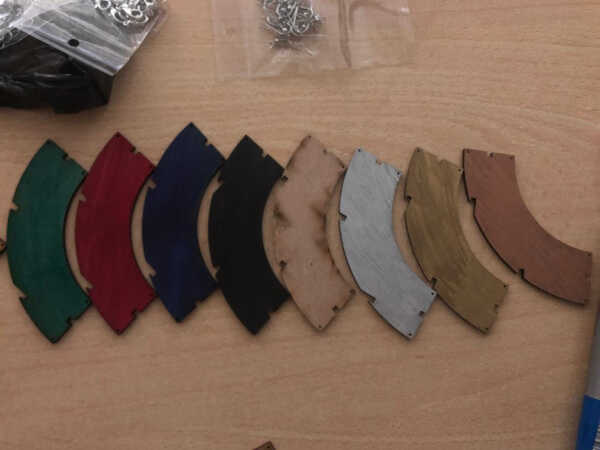
I have prepared the rings and the wires and the colored markers so I can color my MDF and make it look prettier for my accessories collection
And here are the results; Pretty satisfying!
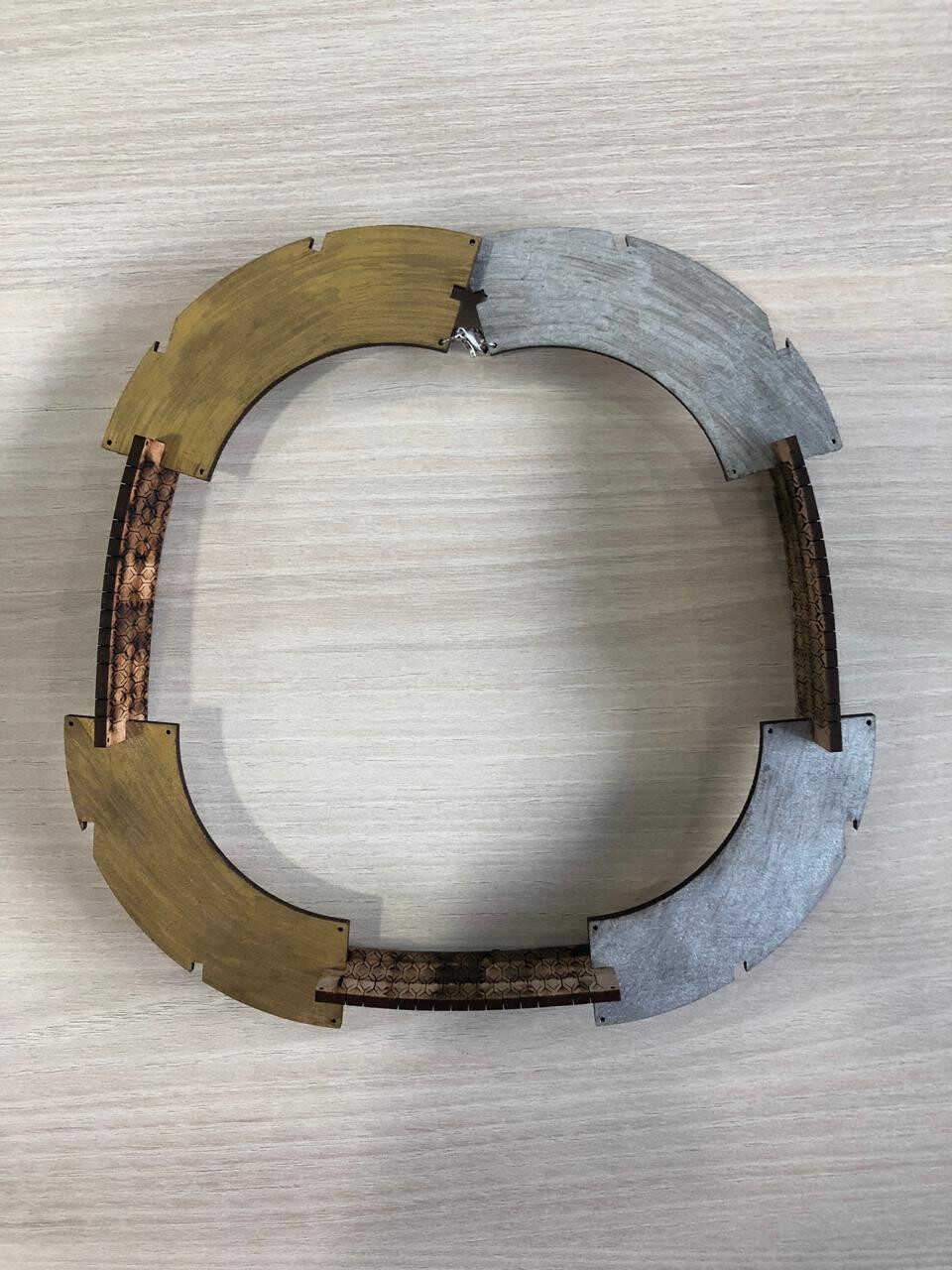
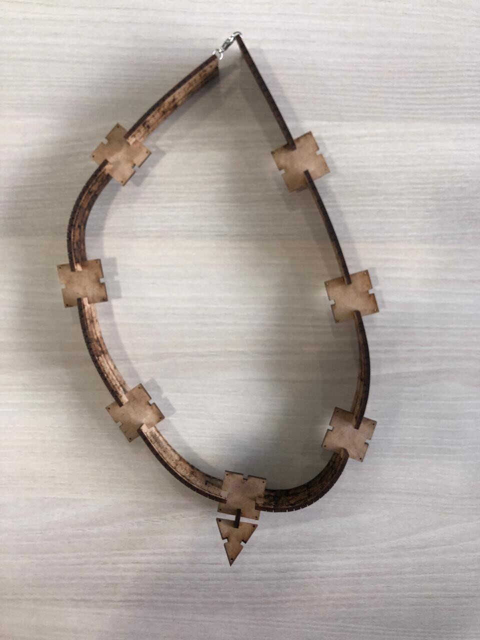
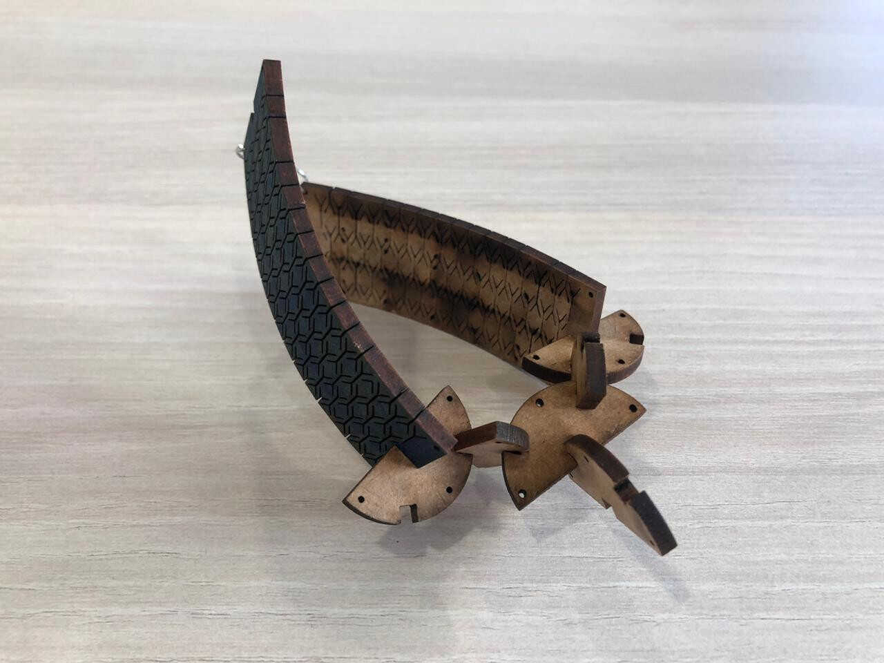
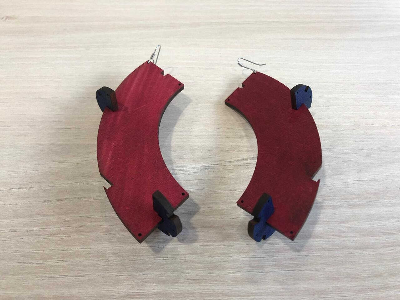
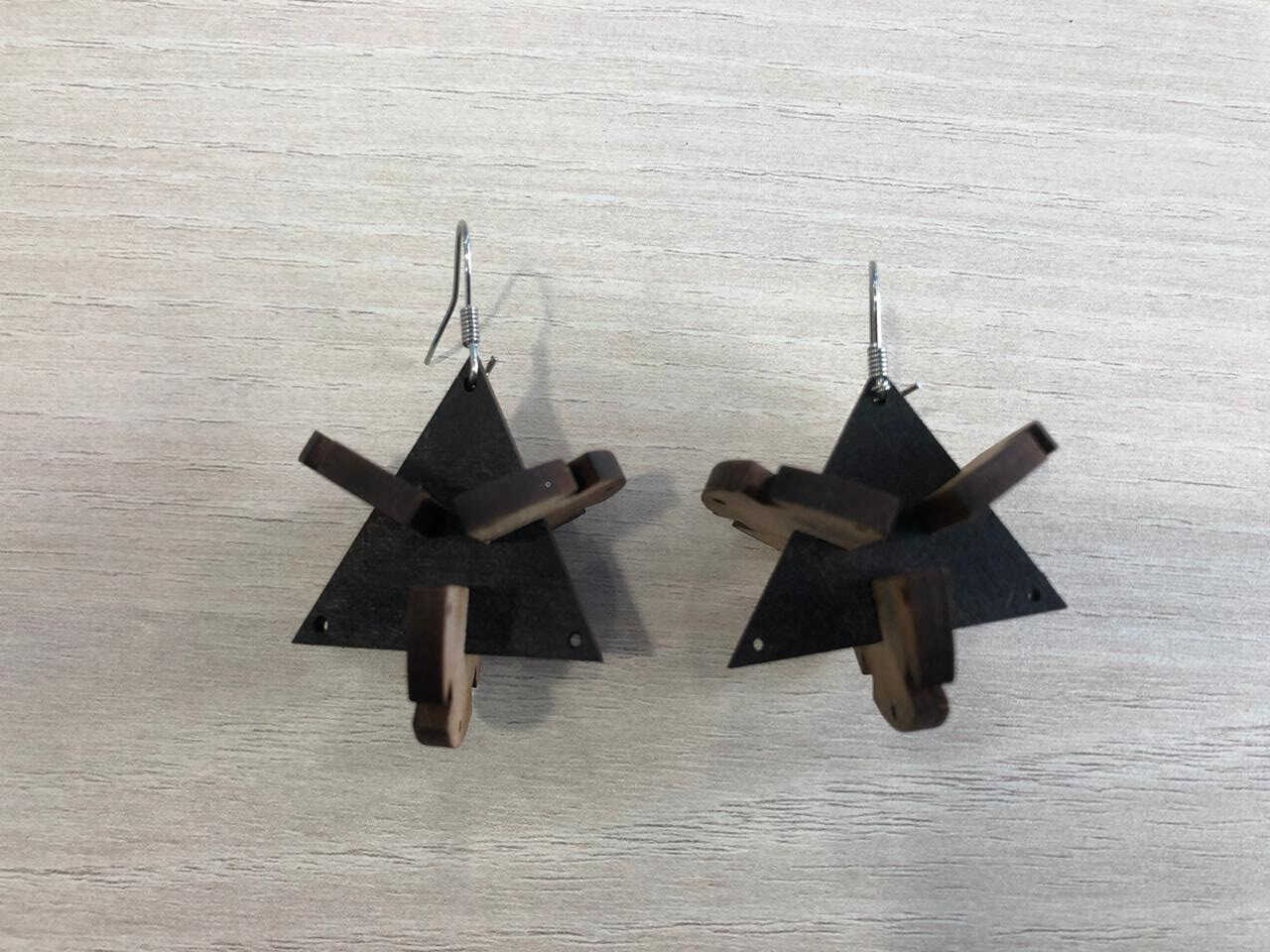
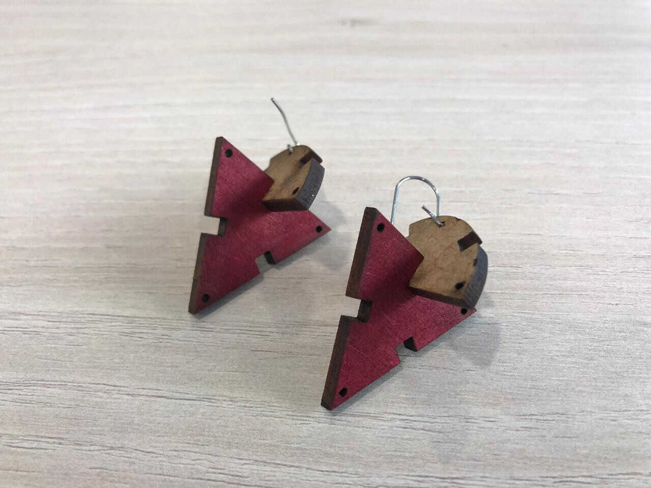
And you can keep playing with them as much as you want; The options are quite endless!
I have actually missed to chamfer my corners, so I advise you to do so so that the pieces can smoothly fit into each other. And I advise you to use the command "JOIN" in your DXF file before cutting your press-fit kit (Ctrl + A and JOIN). This command will join all your lines so that your laser cutter does not go over the same line many times.
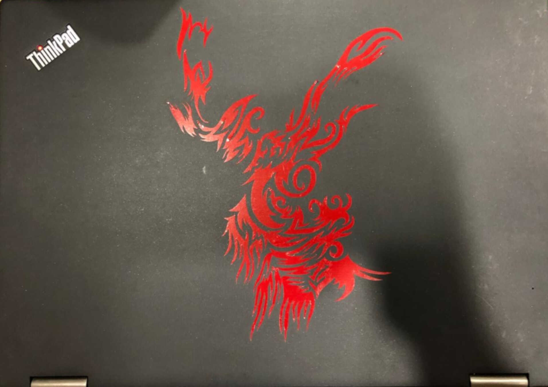
I have chosen to cut one of my tribal drawings and to stick it on my laptop
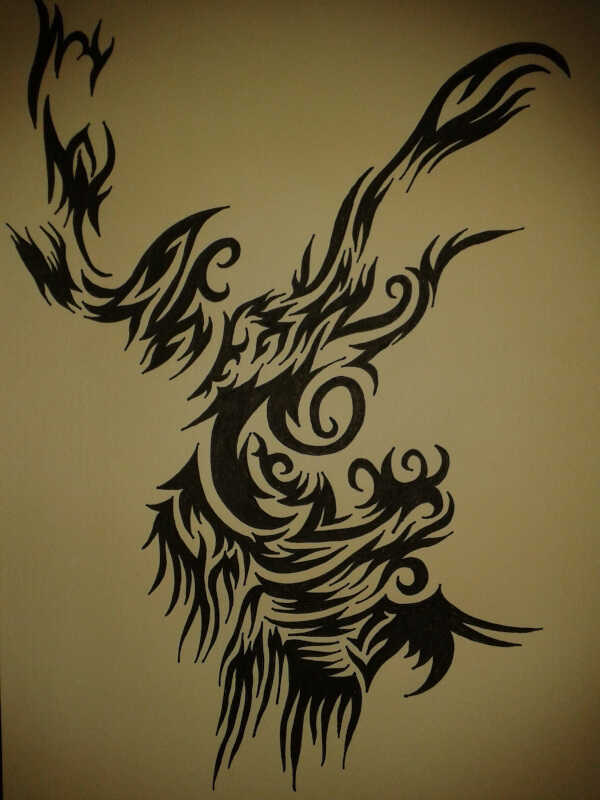
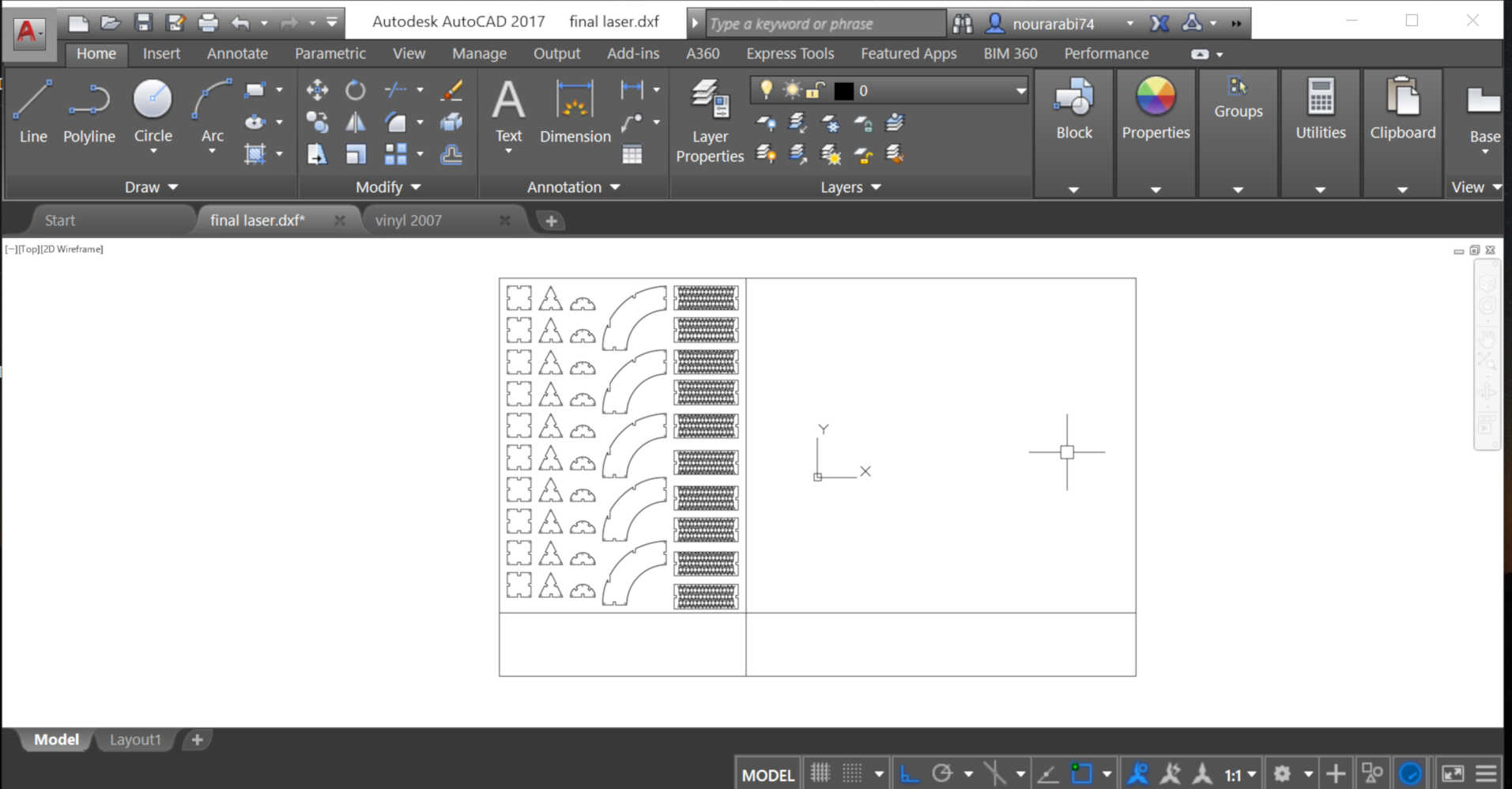
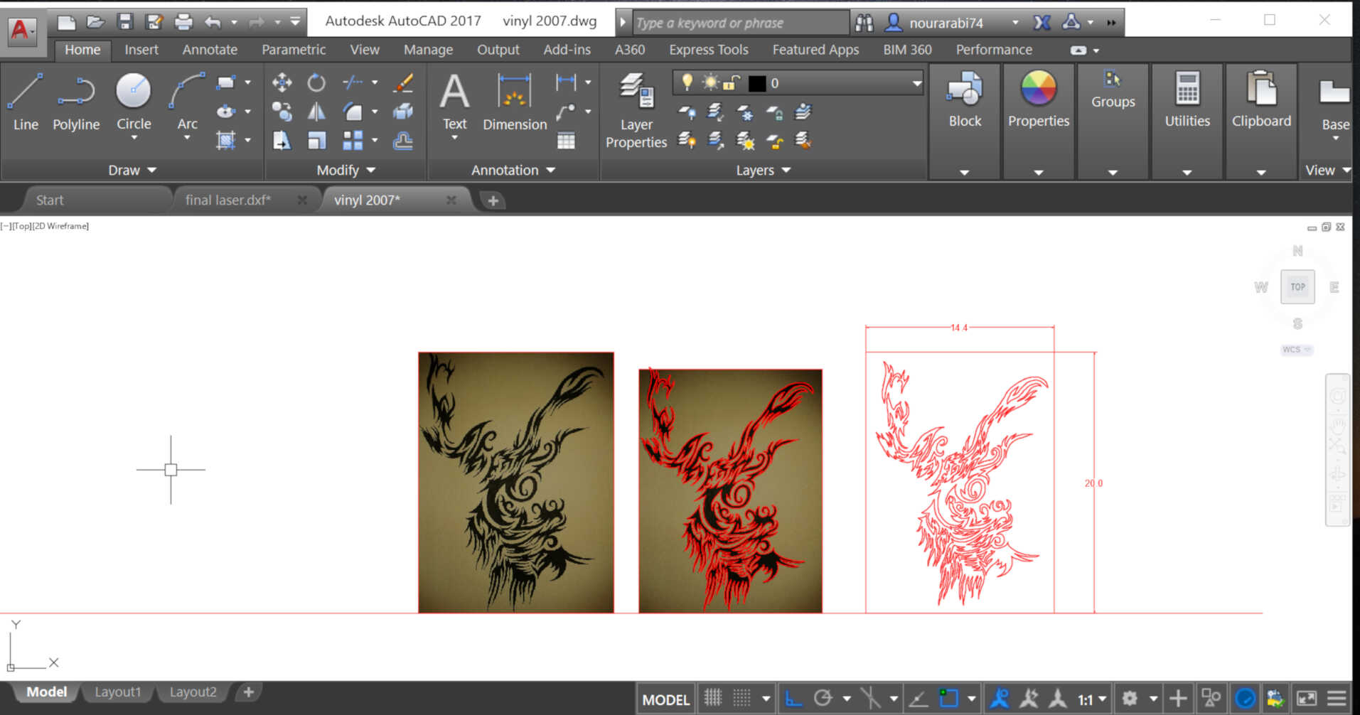
I have then inserted the above photo of my drawing into AutoCad and traced it using SPLINE, then scaled it to fit onto my laptop (20x14 cm). The file needs to be saved as DXF.
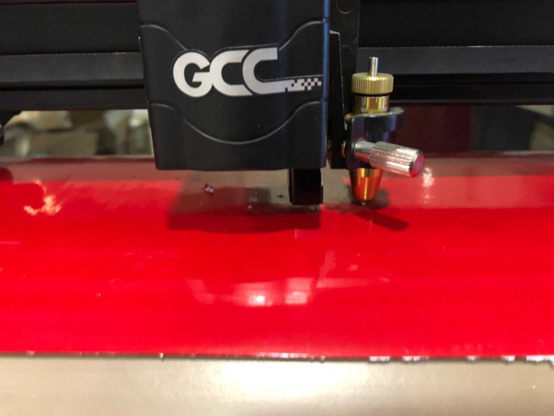
I have chosen the red as my vinyl color and started to set up the vinyl cutter
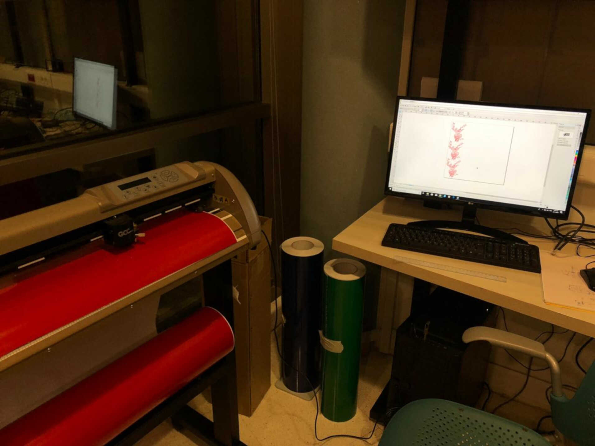
The wheels of the machines need to stay below the white areas
The vinyl cutter will then generate the width of the vinyl used and which is 550 mm

The next step is to import the DXF file to CorelDraw and insert the dimensions (550x550 mm)
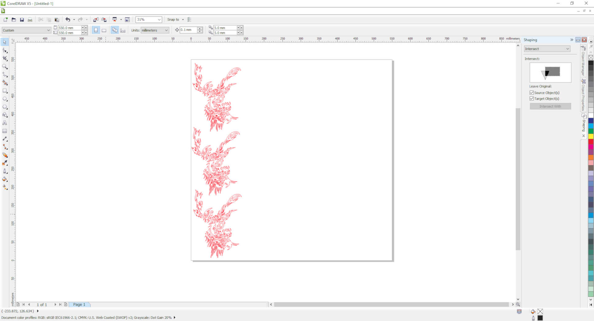
Then print the file with the right settings
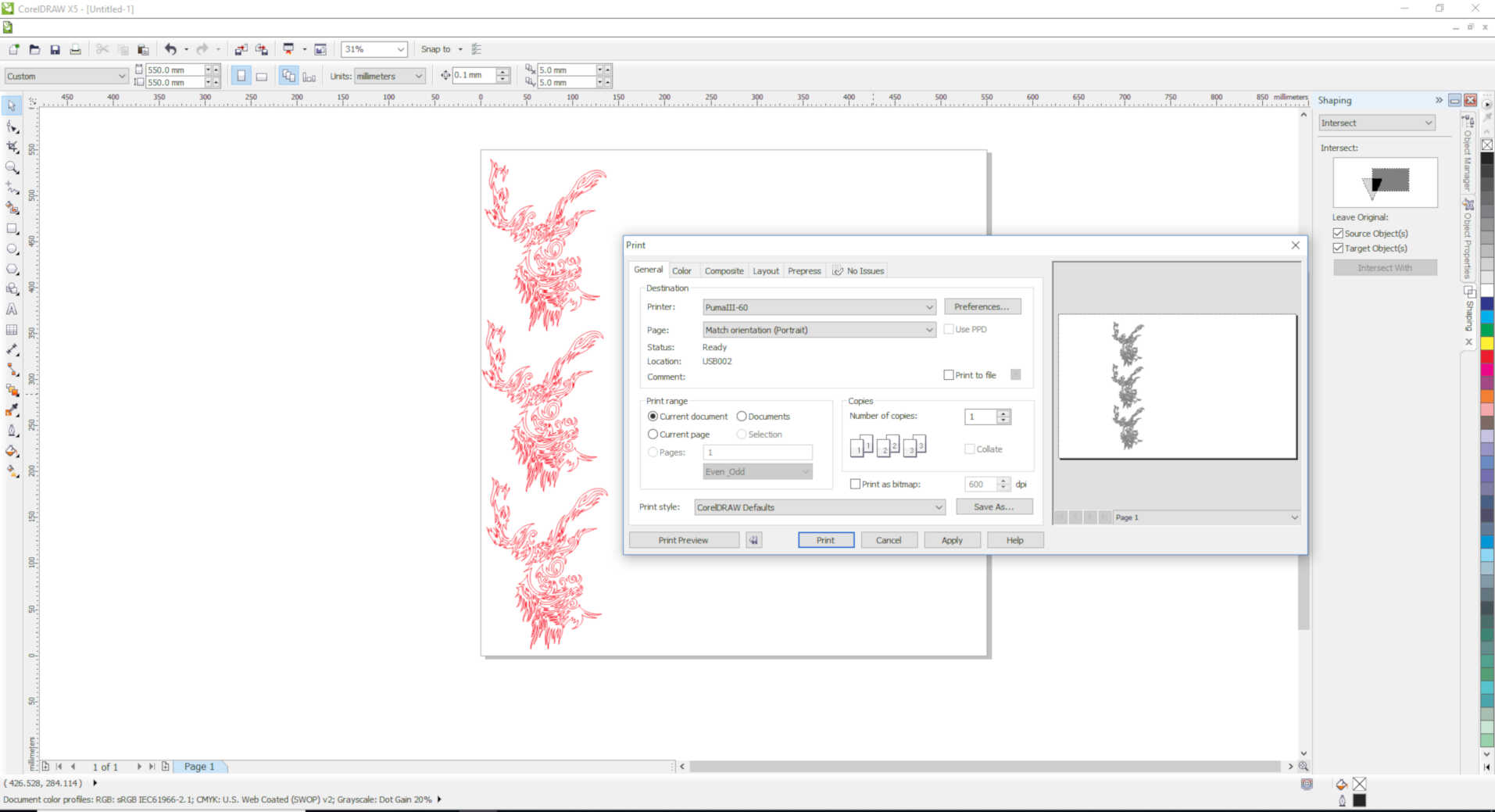
The drawing should be placed on the bottom left corner in the layout
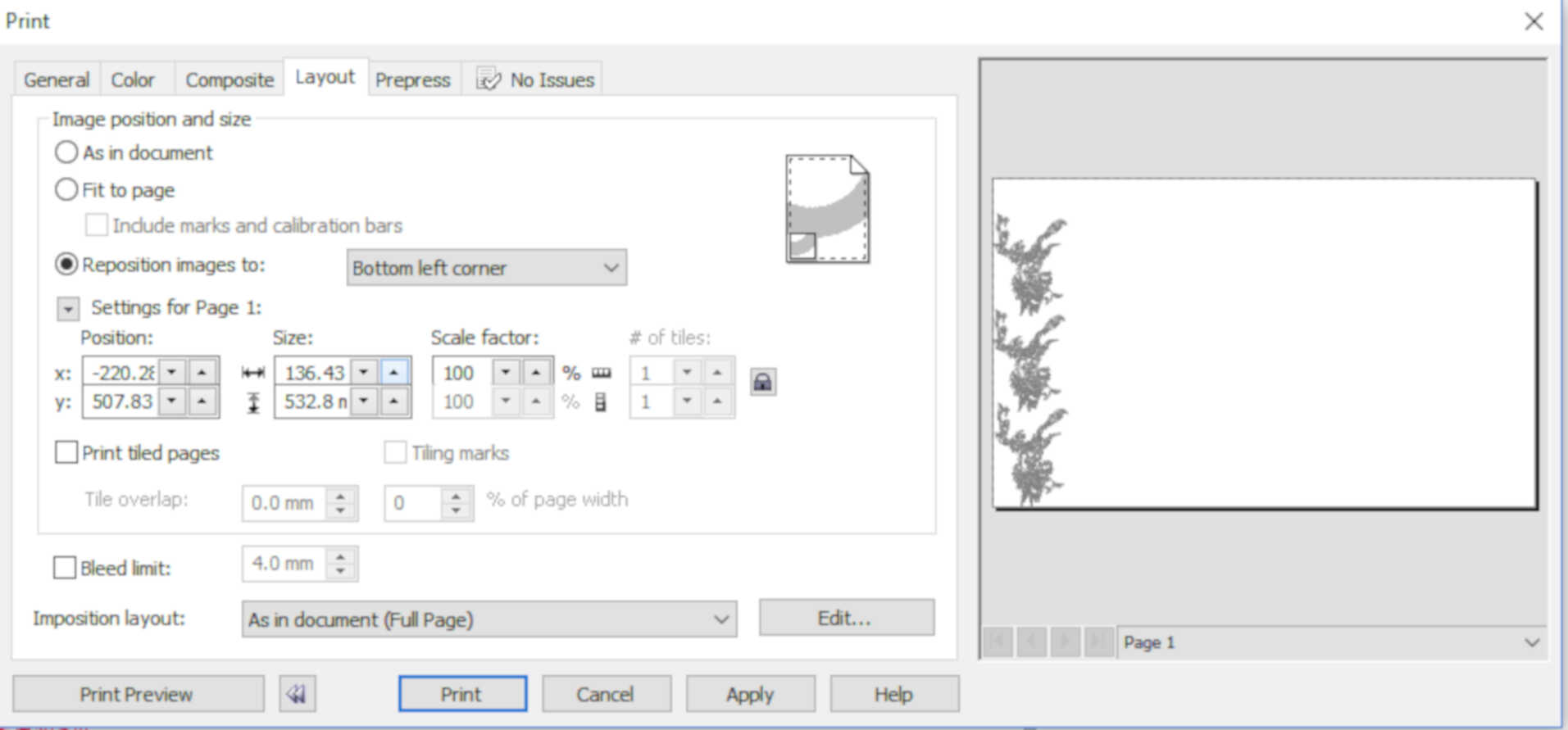
Press PRINT and your vinyl cutter will start to work
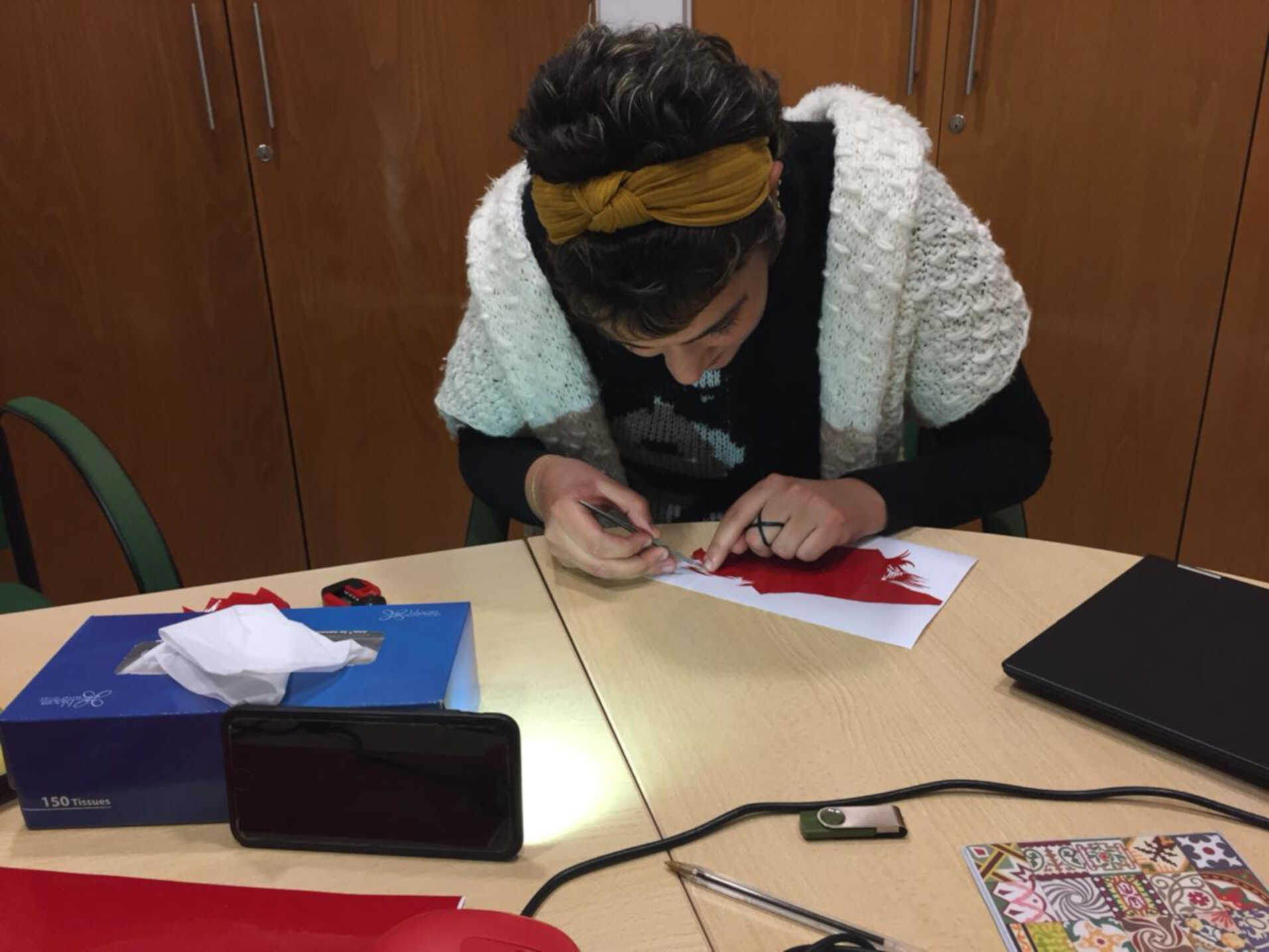
It is time to remove what is not needed and leave the tribal parts using tweezers
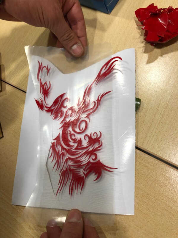
Place the transparent adhesive paper onto your vinyl and start peeling it off so that the vinyl parts stick to it
Then stick the above onto your substrate and which is my laptop top in this case
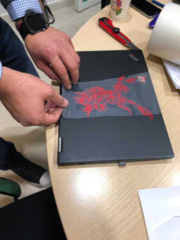
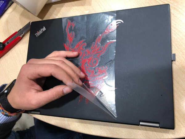
And here is the result
Test 1-Speed Settings, Test 2-Kerf Calculation, Press-fit Kit Fusion 360 & Press-fit Kit DXF File