Cocktail Machine
Week 15 & 17
In week 15 and 17 we had the group assignment to design a machine that included mechanics, actuation and automation.
Alone everything would have been a bit difficult, because my group member Tin came from Croatia and was very limited in time. Therefore I would like to mention at this point that the construction of the cocktail machine would not have been possible without the additional support of Jörg, Ilhan and Benedikt.
Idea
As an idea we had several machines, but we wanted to build a sustainable machine that could also be used for future events. We wanted it to be something that would represent all the skills learned at the Fab Academy. After some research on the internet we found cocktail machines over and over again - the idea was good and off we go!
Designing the machine
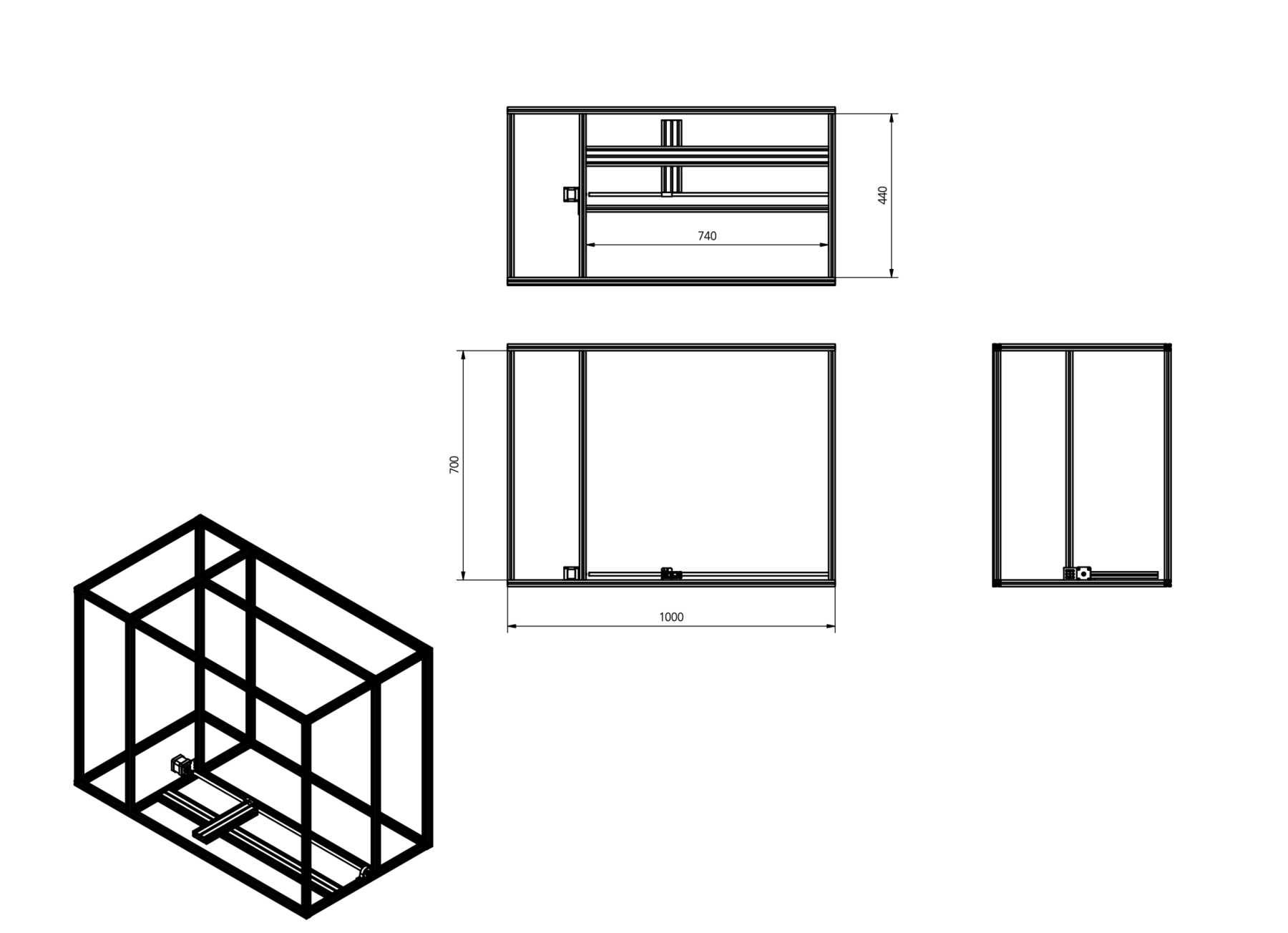
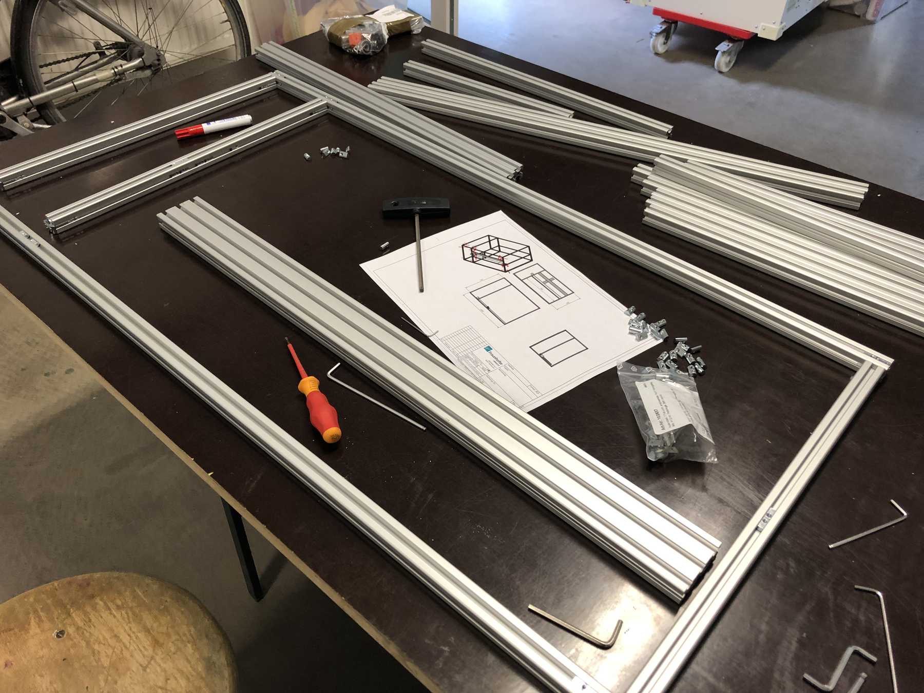
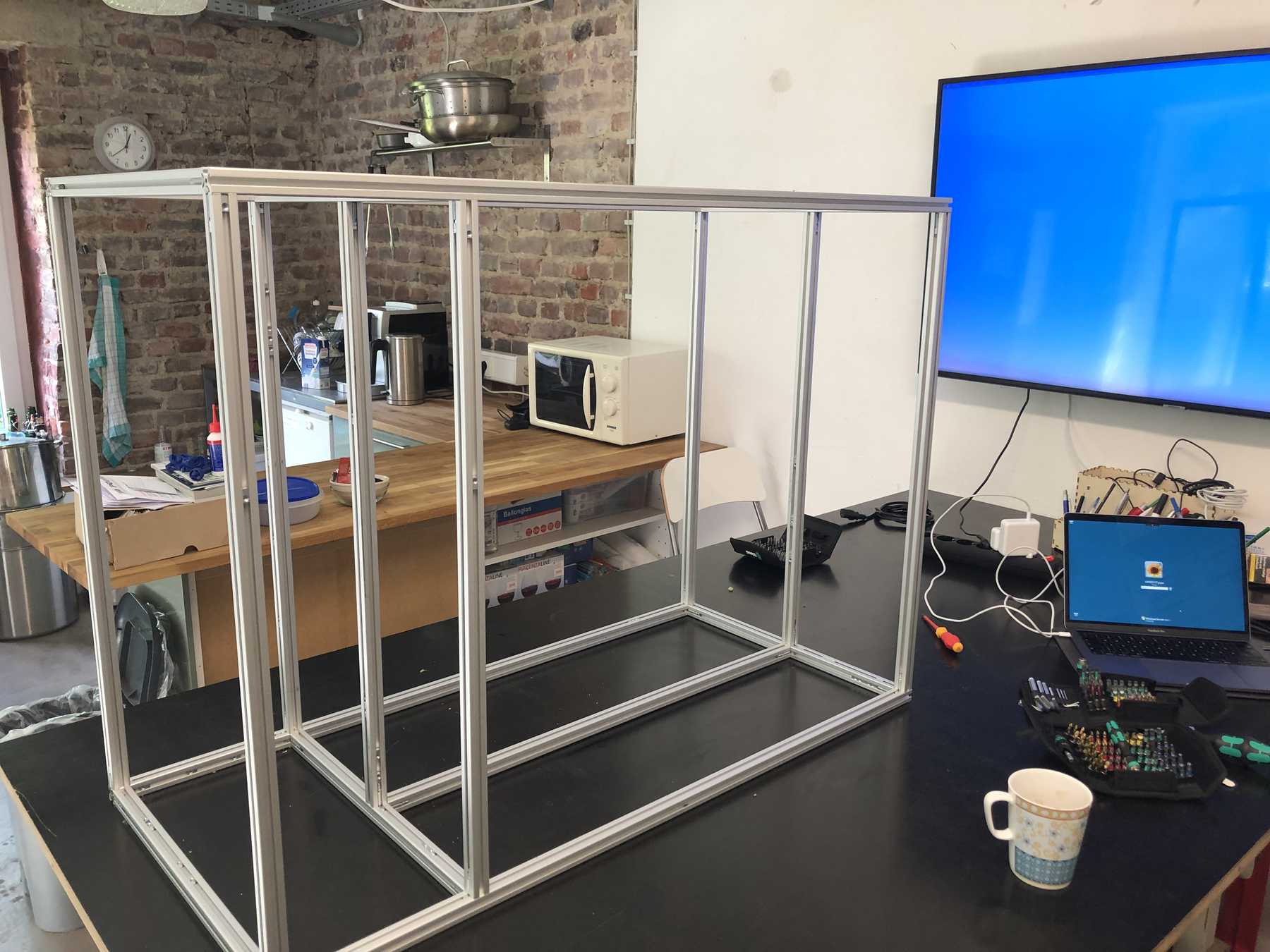
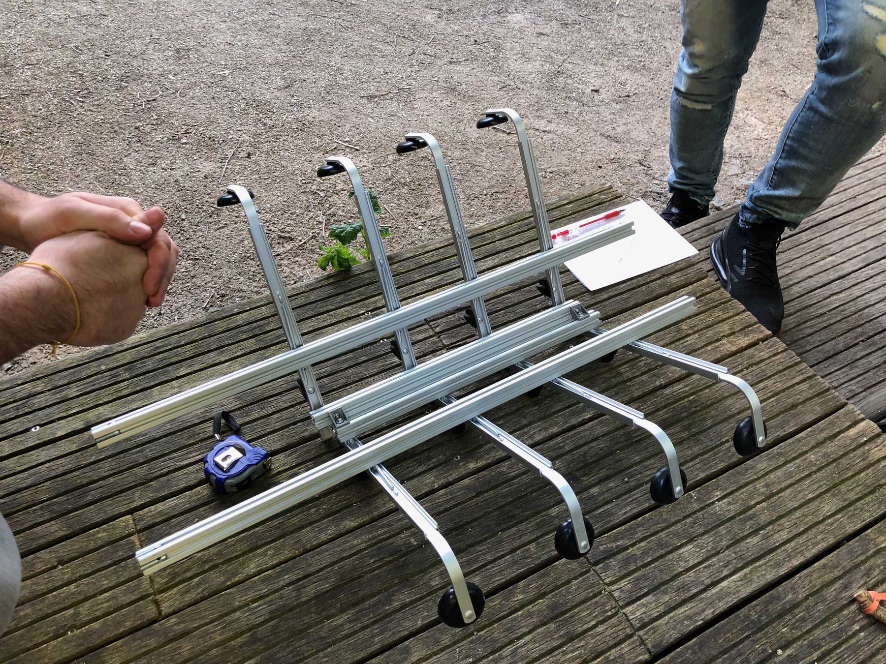
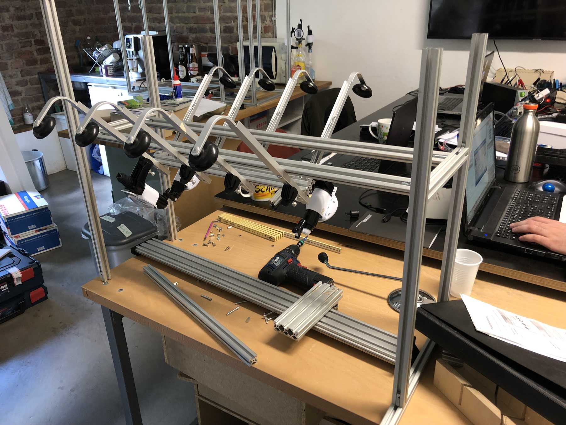
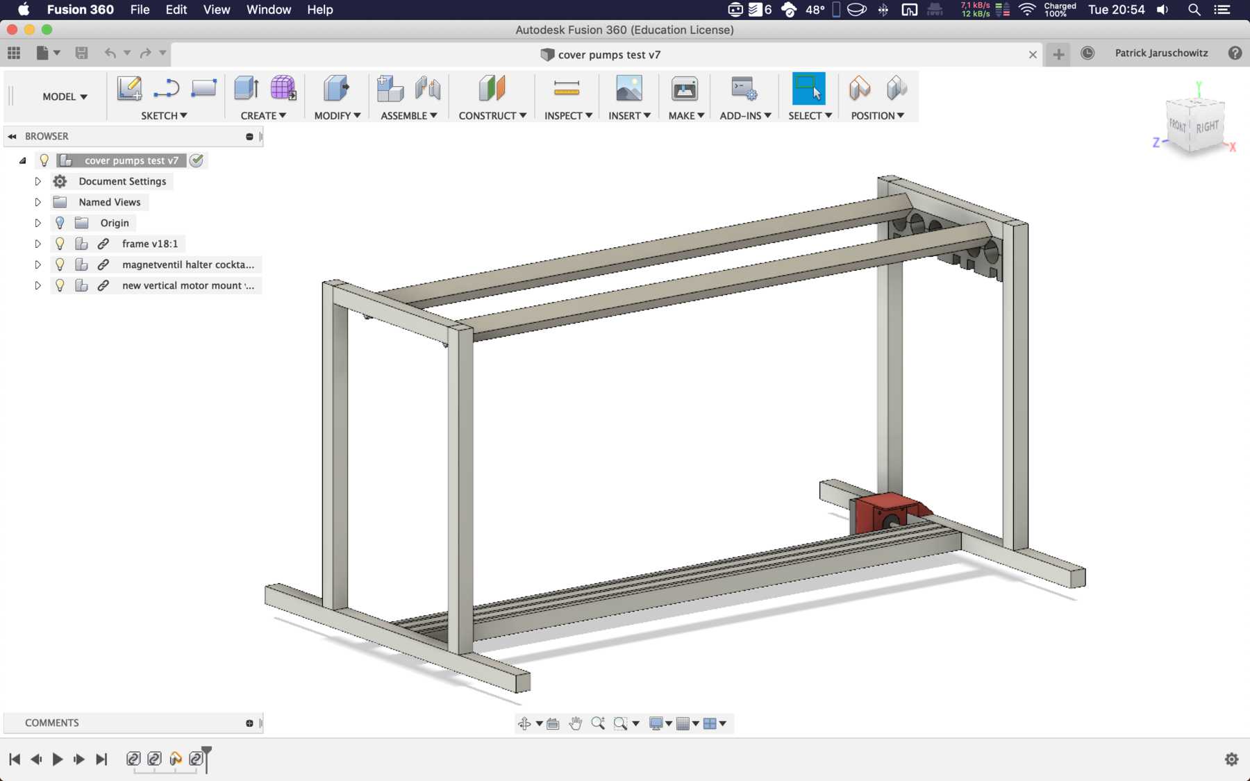
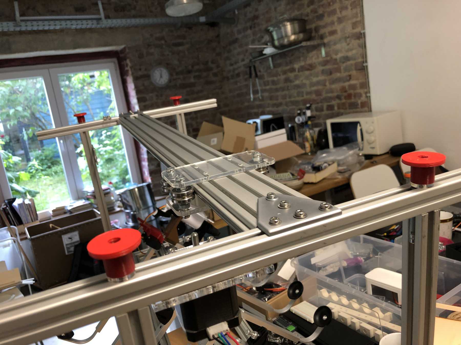
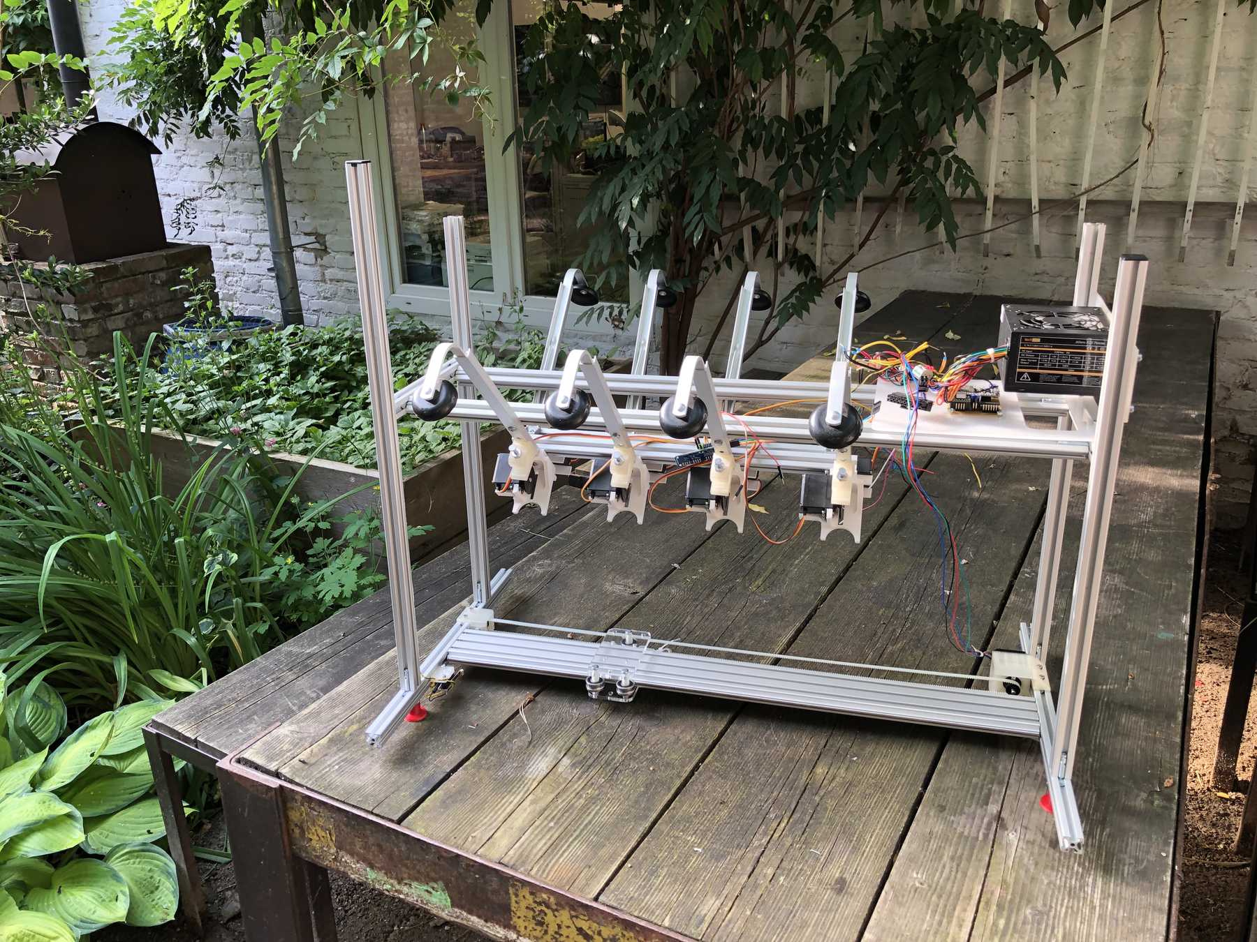
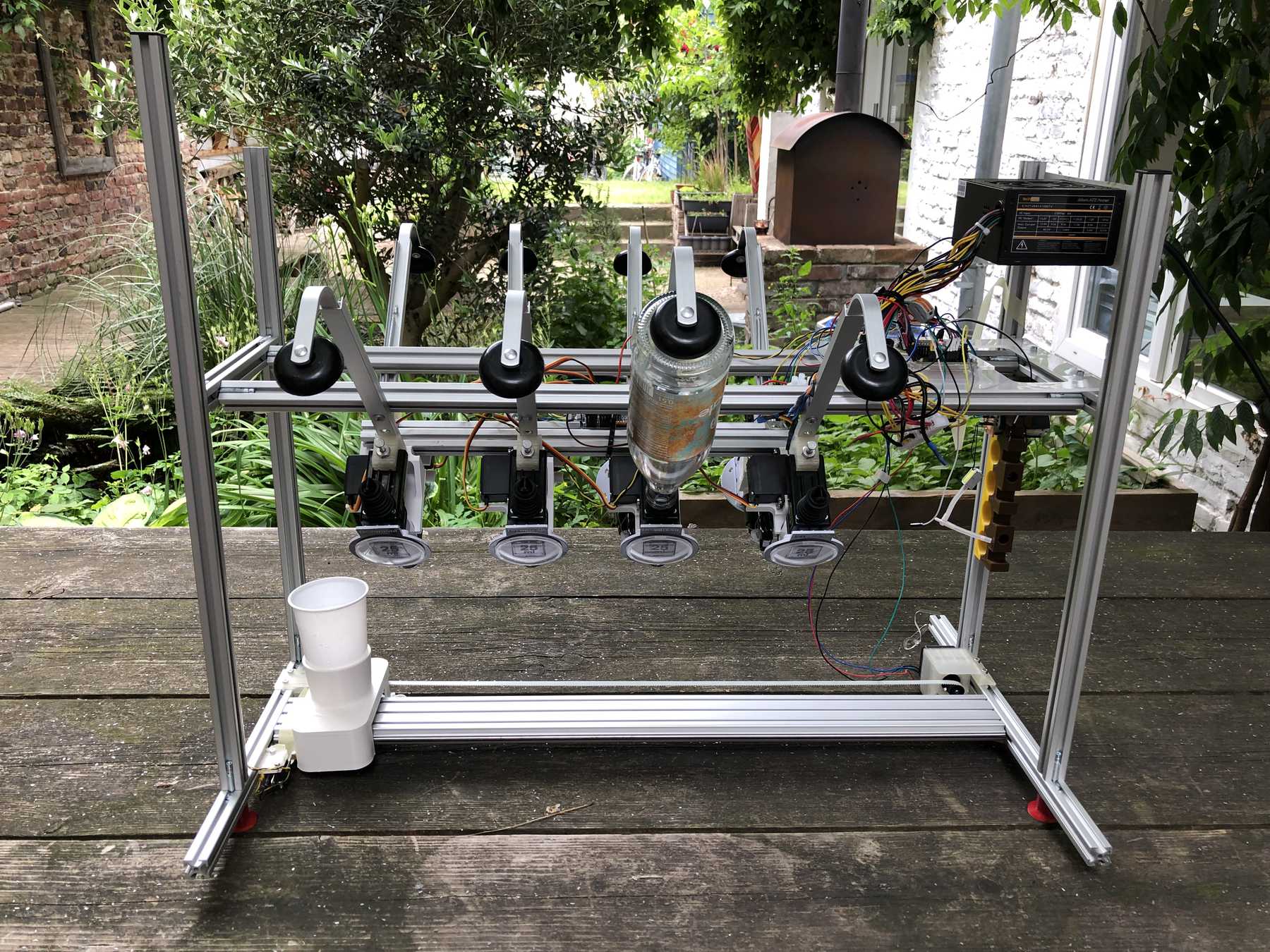
The decision was made early. As a precaution we already ordered the profiles and created a frame for the cocktail machine. During the construction we noticed that the cocktail machine is much too big, as the pictures show.
We were thinking about the leadership and we just didn’t like it.
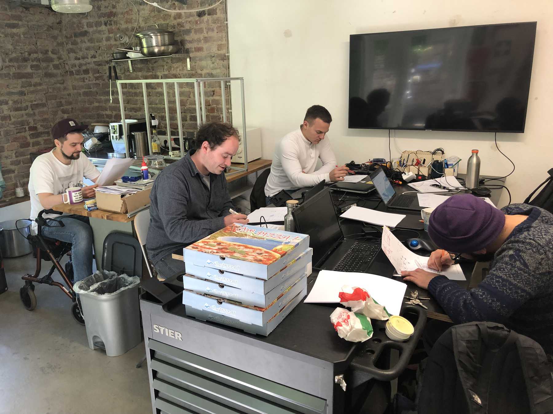
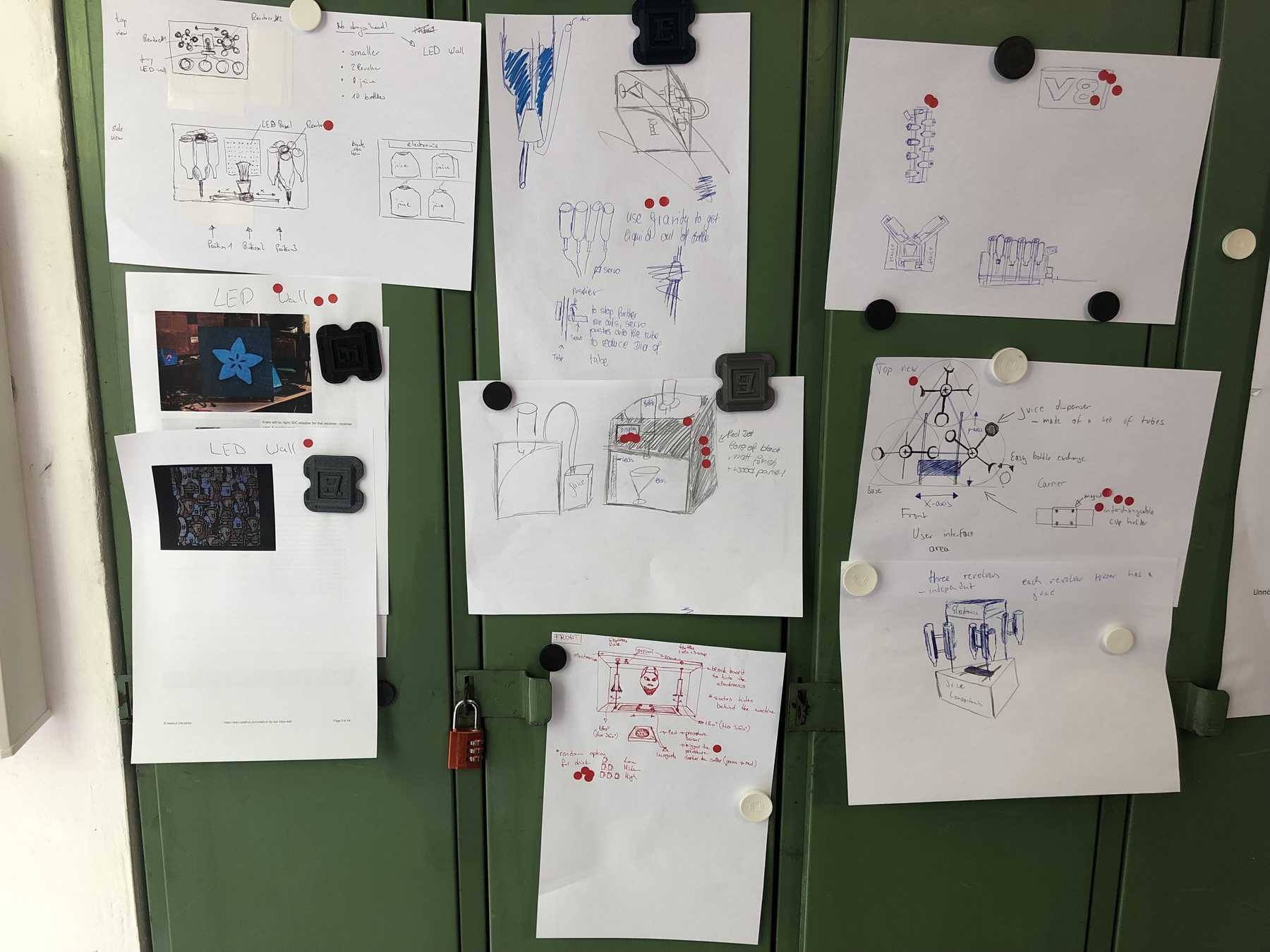
So I invited my friends to come together and look for solutions. We used some creative techniques and ended up with a Wall of Ideas. My beloved dot voting was to decide on the final design by the group. This phase was only interrupted by a delicious pizza.
Assembling the frame
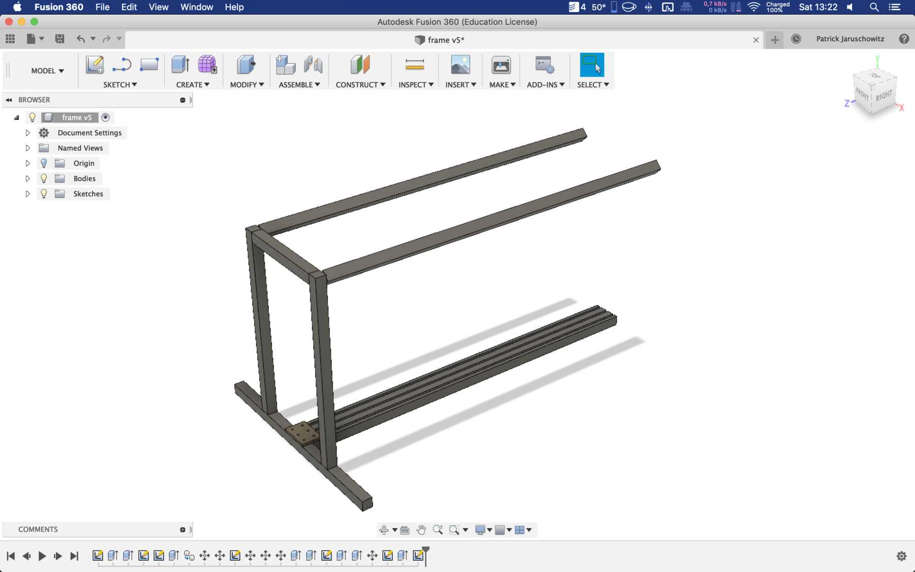
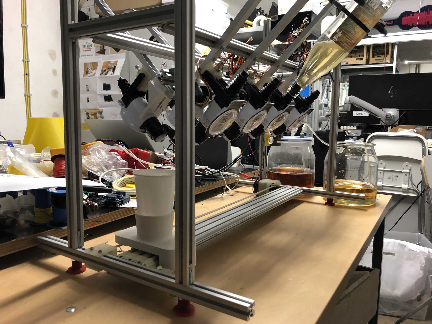
The group has decided: It should be a cocktail machine in the design of a V8 engine. We started with the construction of the profiles and the shortening of individual elements. Since we still don’t know exactly how long the individual profiles will be later, how much space we really need at the end, we left some room.
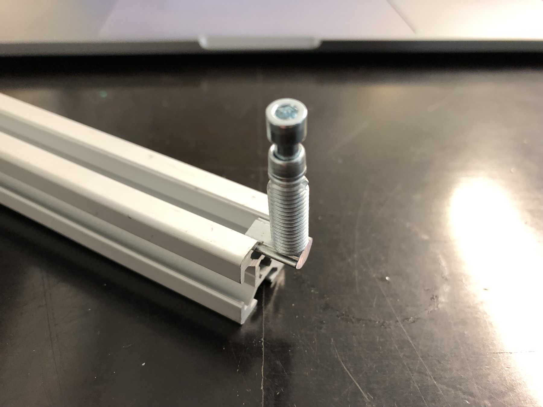
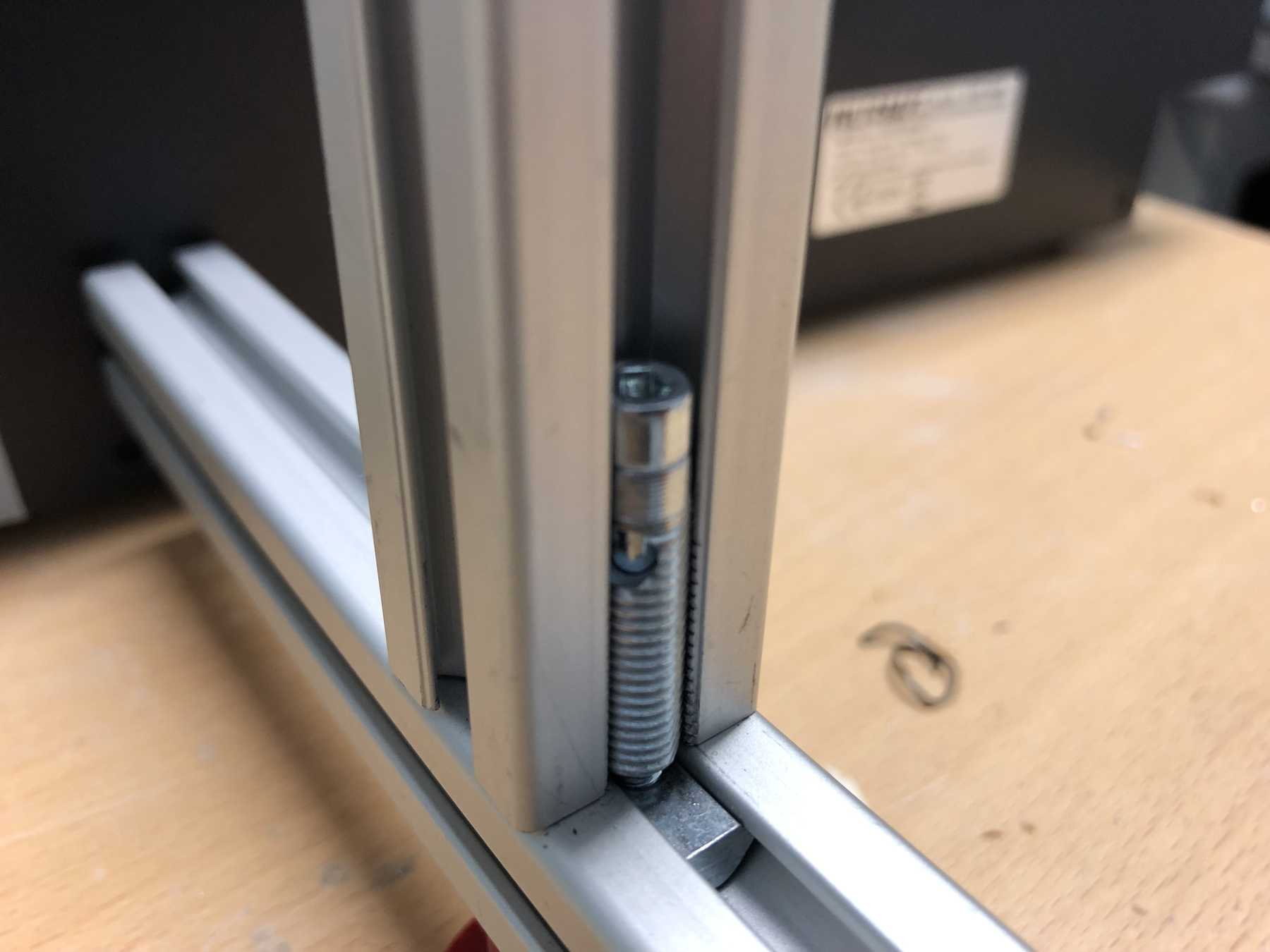
Of course some parts were missing now. The profiles were connected directly via automatic connectors, which are designed to securely connect two profiles. The shell is drilled in self grooving by using a suitable hexagon socket screw key into the profile. The T-nuts are then inserted into the other profile.
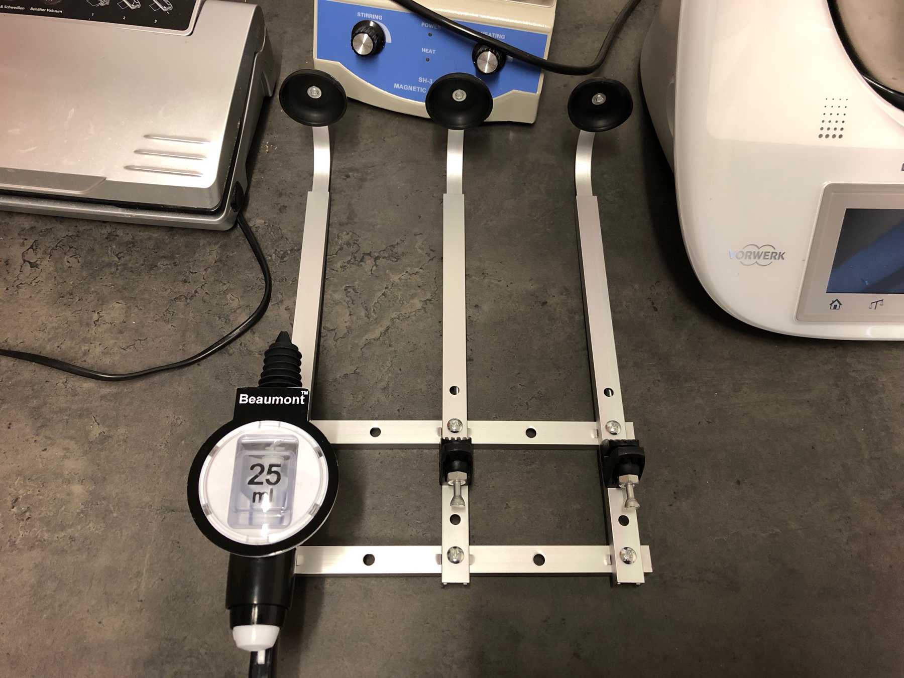
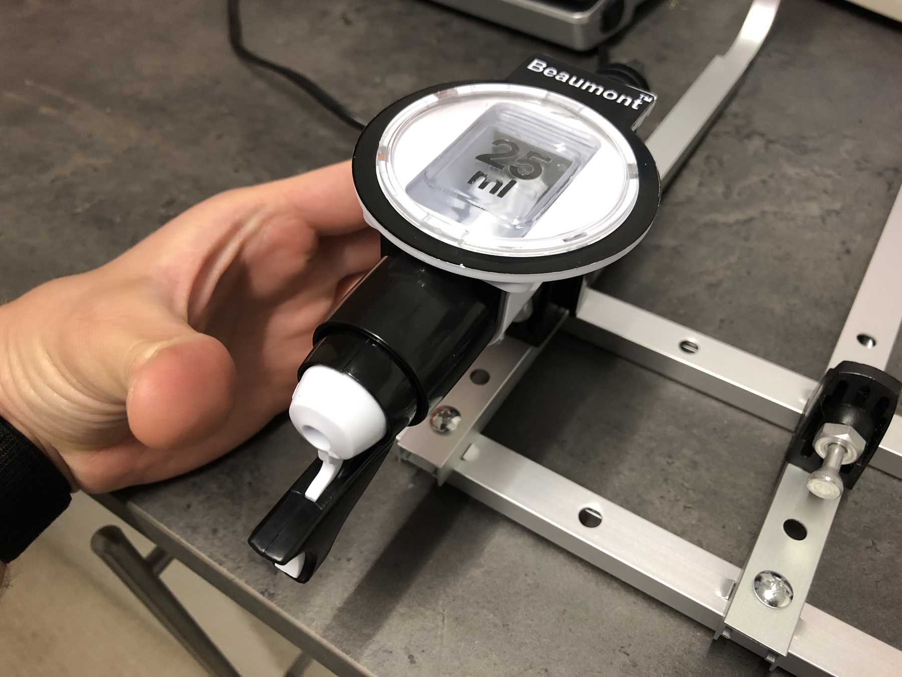
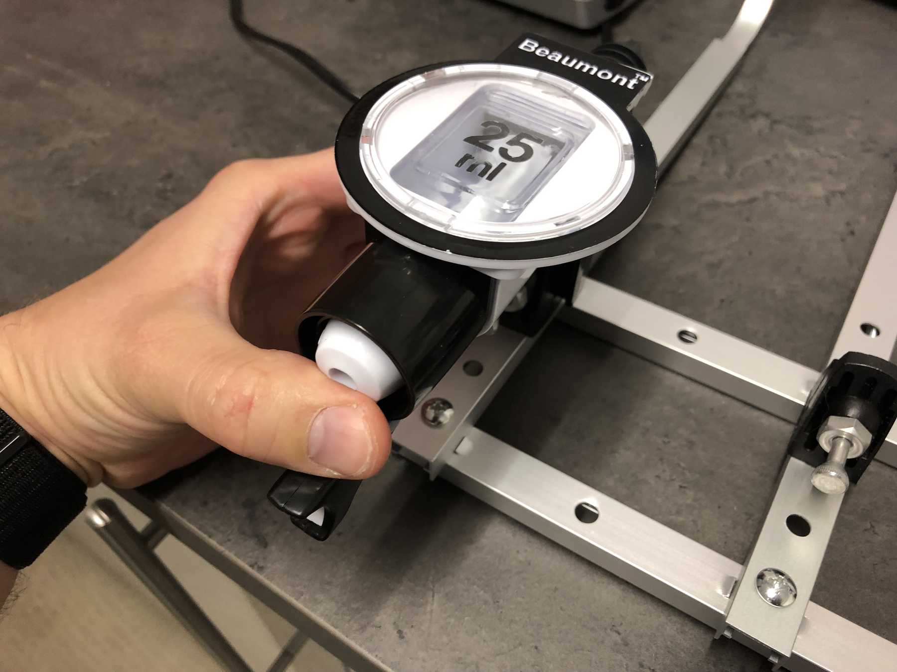
For the bottles we bought the following bottle holders with integrated 25ml dispenser, which has a release mechanism. The bottle holders looked as follows and worked very well. These bottle holders are from the company beaumont and the product has the name 25ml Metrix SL.
In the meantime the frame has developed. Step by step we came to the following conclusion:
All right, all right. The outer frame stood and further?
Designing the missing parts
Now individual elements had to be optimized so that the entire machine could be improved and function automatically. The following points were missing:
- The lower profiles must be on one level.
- Feet must be designed.
- The holder for the bottles must be turned upside down, so a new design is needed.
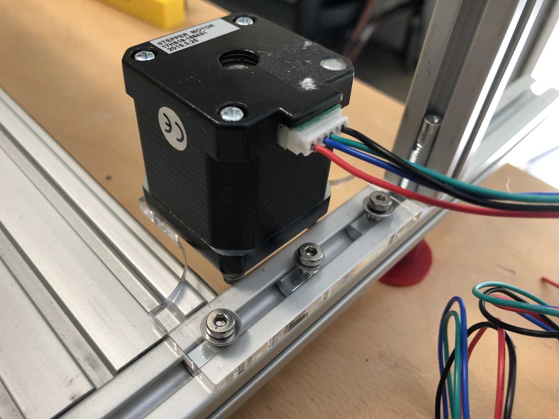
- The stepper motors must be mounted differently
- The cup holder must be completely redesigned. Here a modular design is the best solution.
- A compartment for the electronics has to be designed.
- The dispenser mechanism needs a design for an integration of the servo.
- A nice housing must be designed.
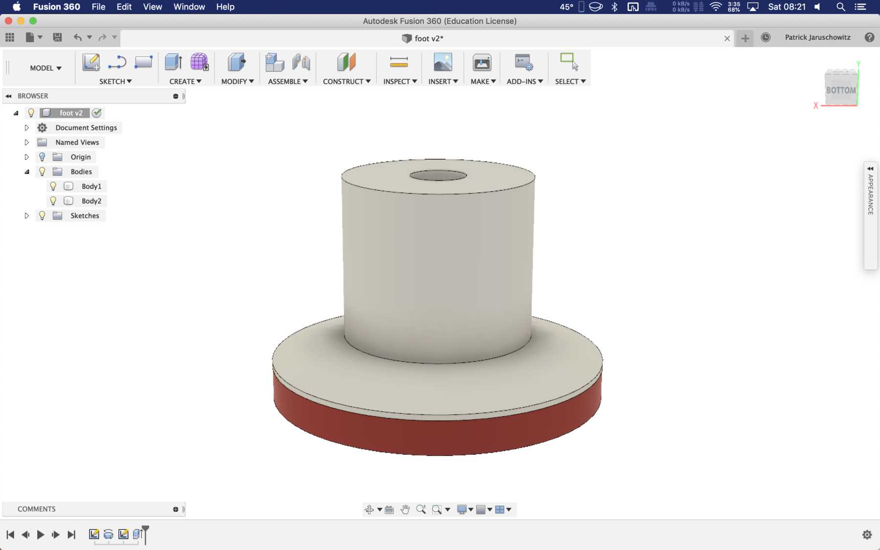
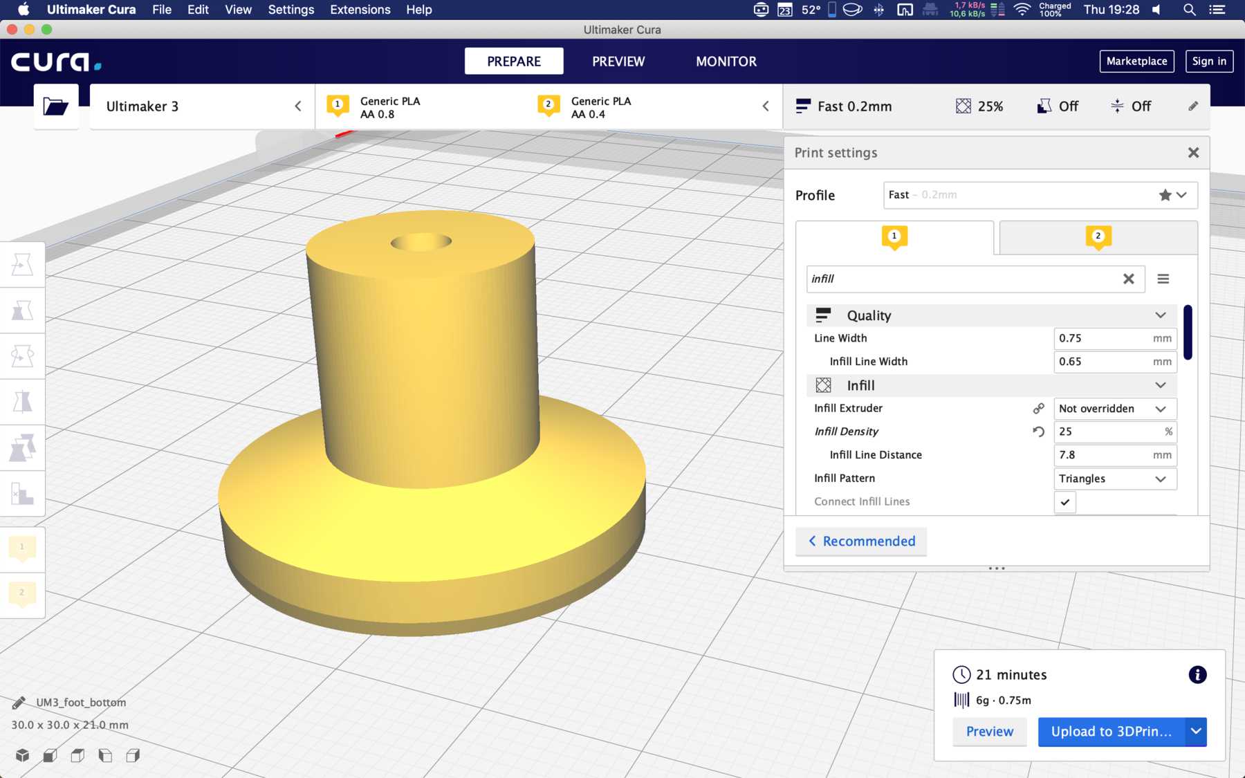
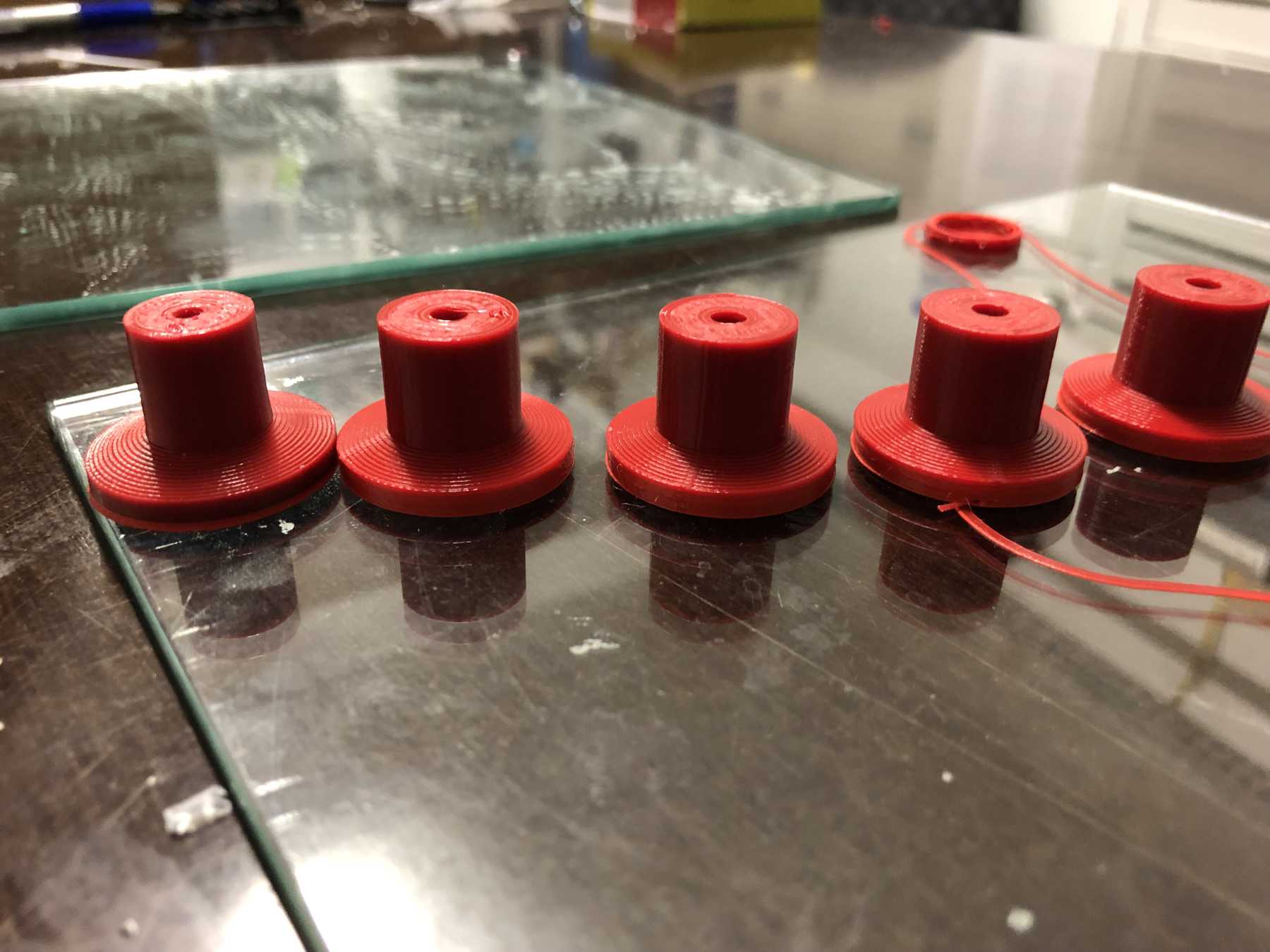
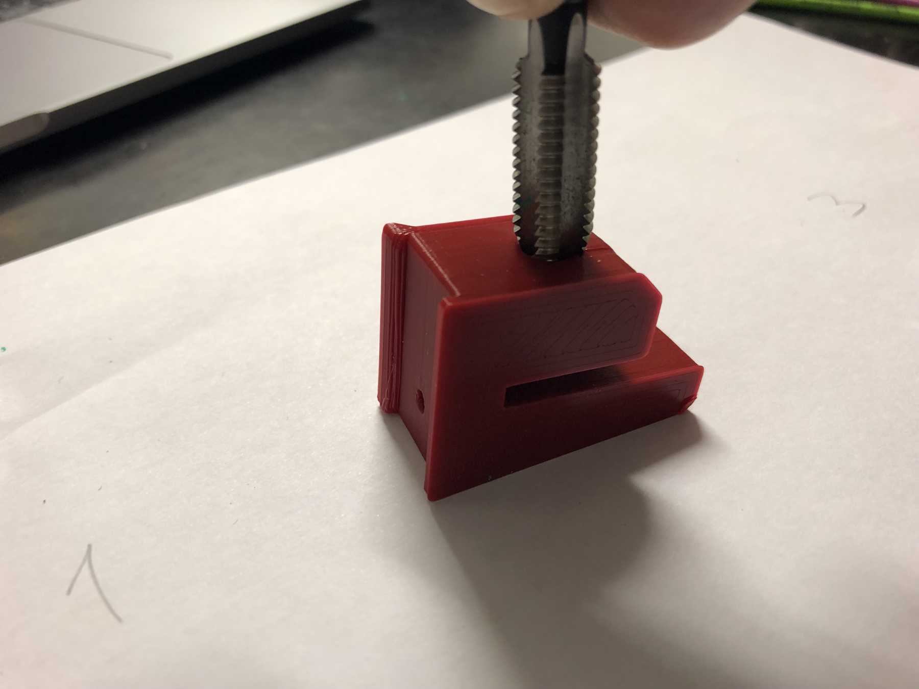
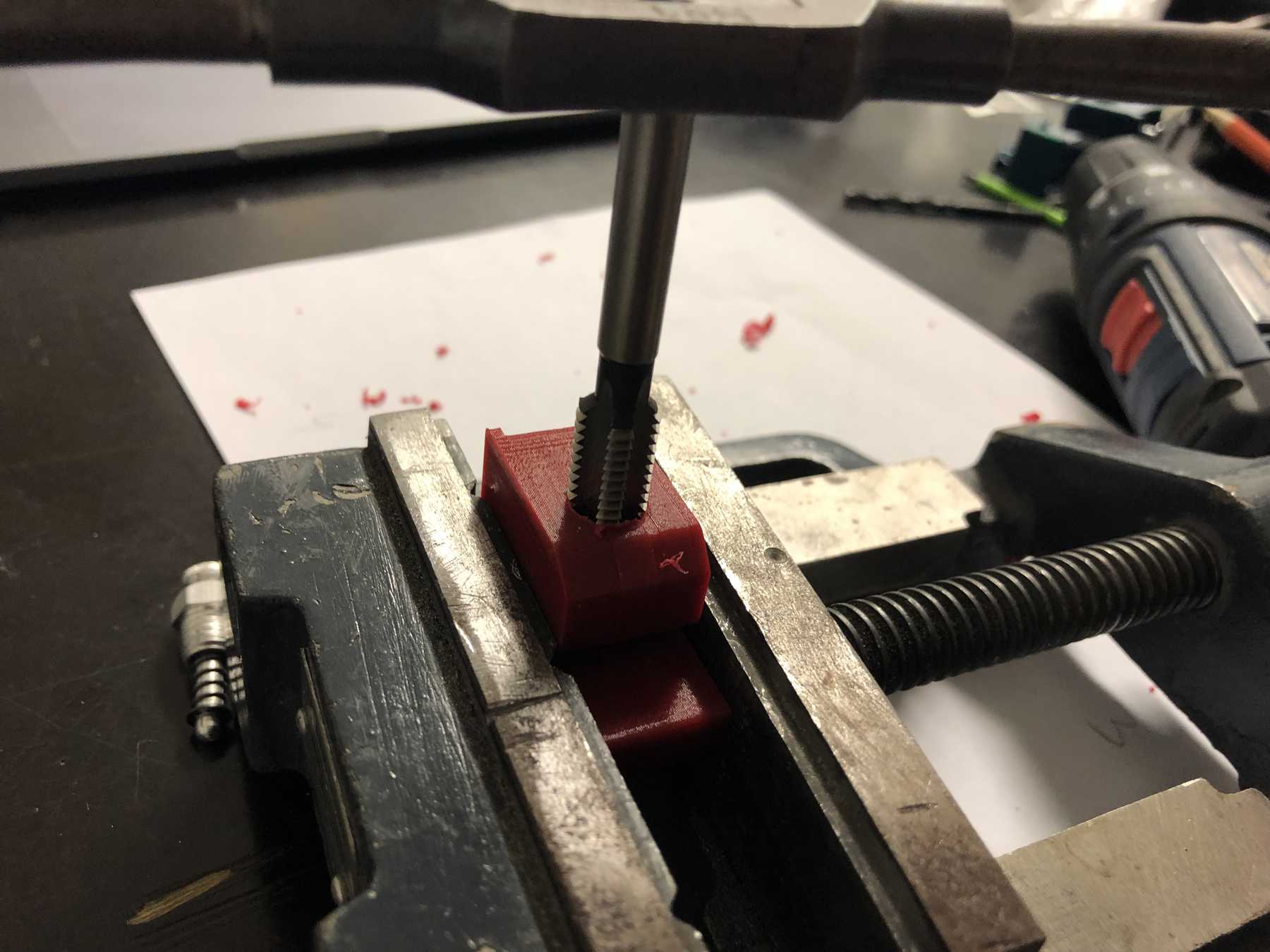
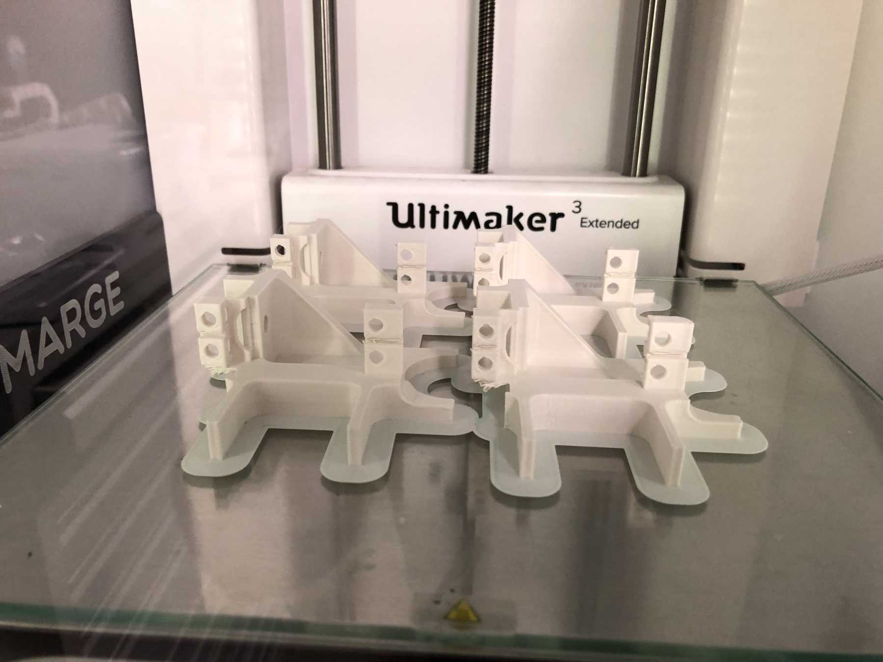
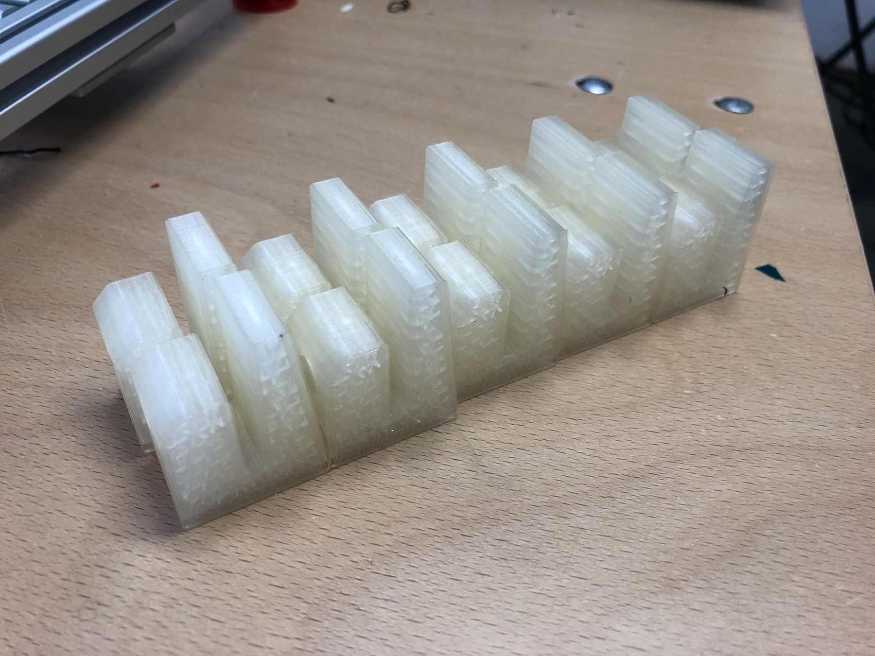
Foots for the machine
The stands must be attached to the machine so that there is still space under the carriage plate. I wanted to print two components here. The upper part is made of hard PLA and the lower part of SoftPLA for more grip. The whole design looked like this and the finished parts:
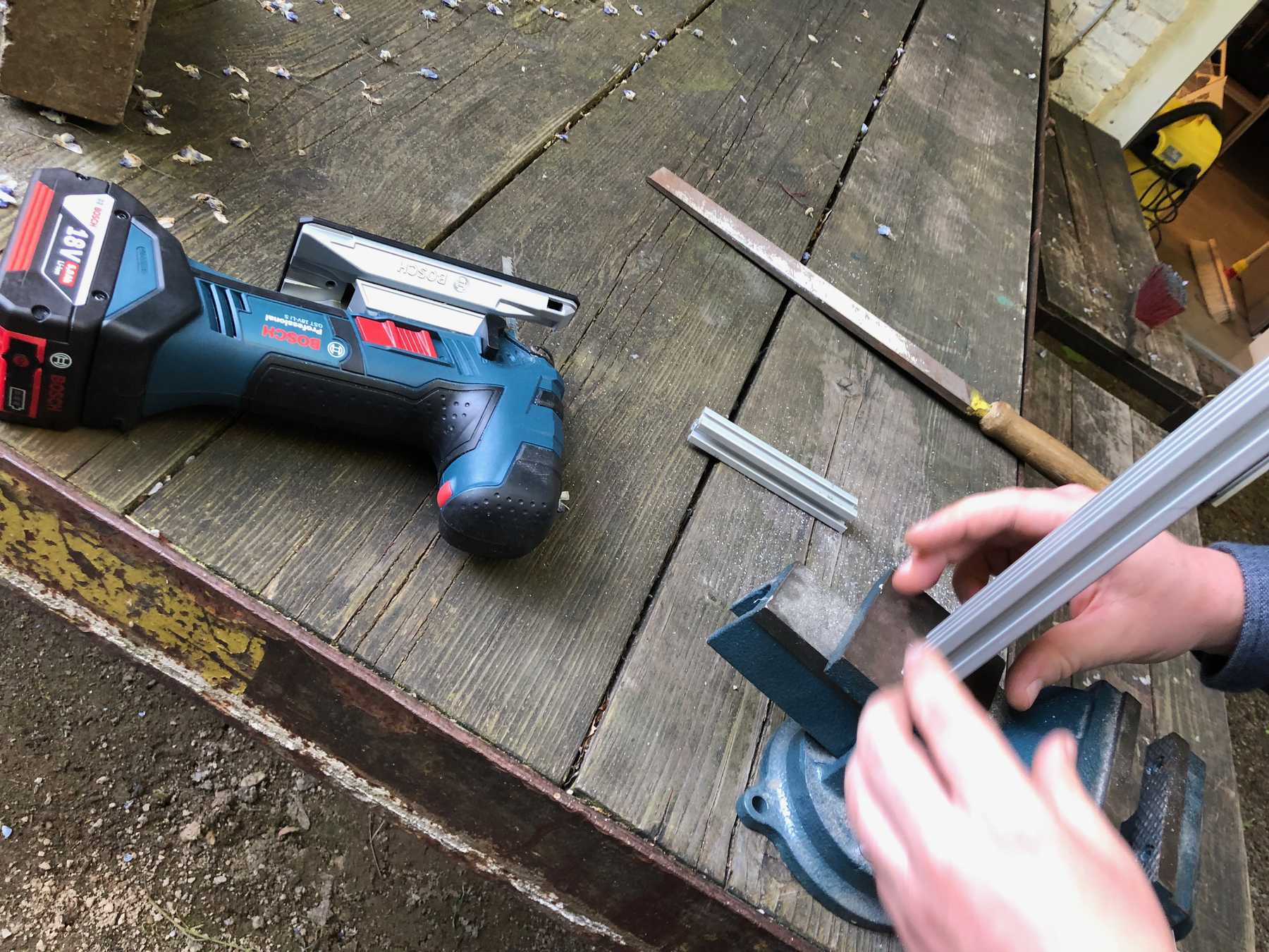
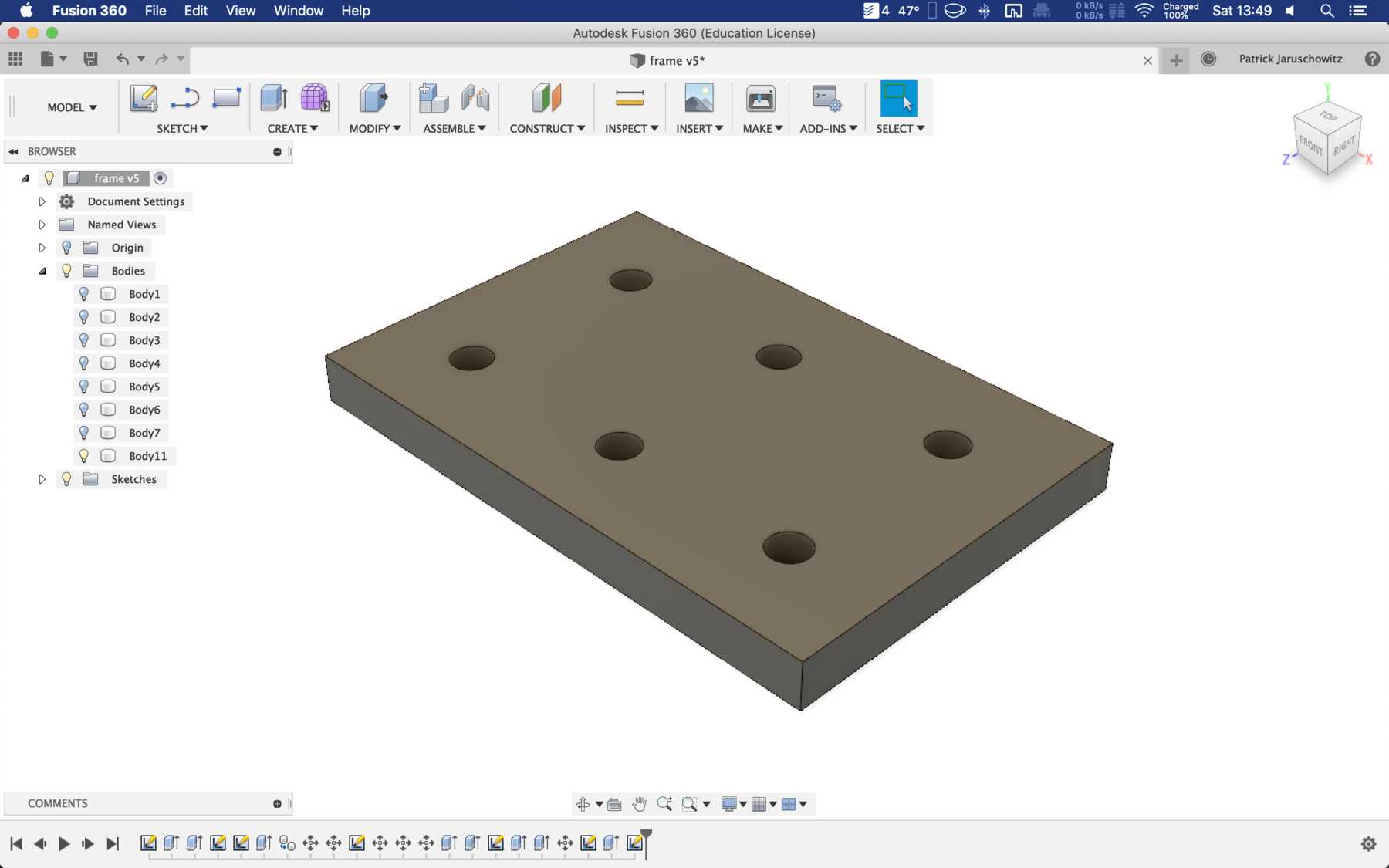
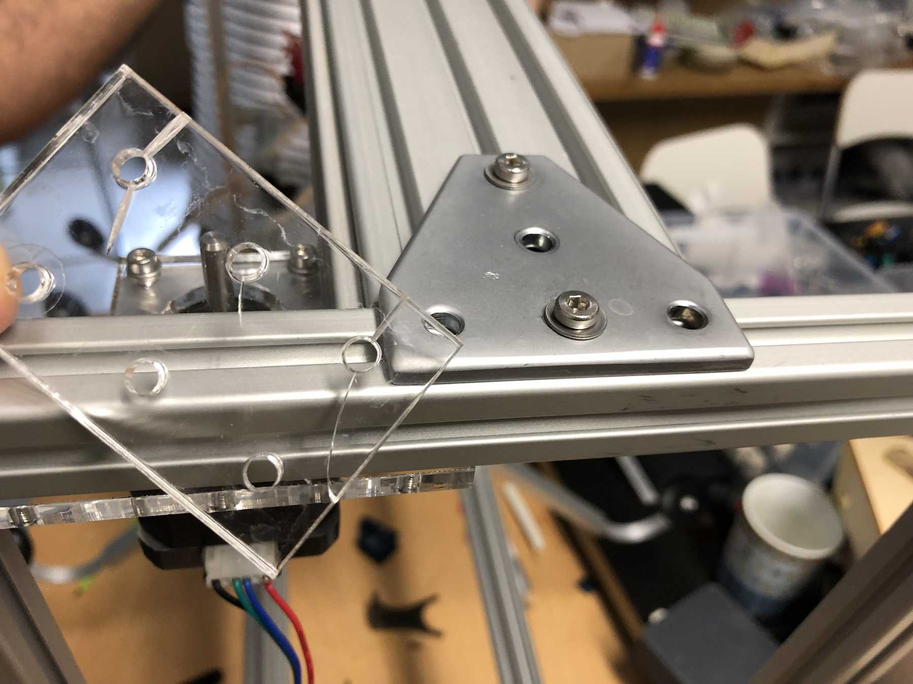
Connecting piece for the profiles
Next, we needed connectors for the profiles to be on one level. For this purpose we have drawn the following design. While screwing together the acrylic glass cracked several times. So we decided to simply take an aluminium rail - and the issue was over:
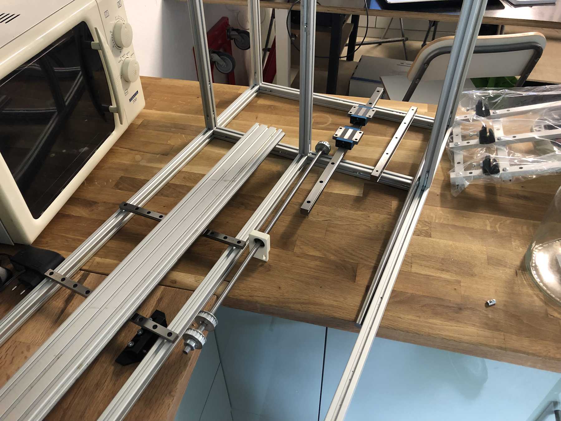
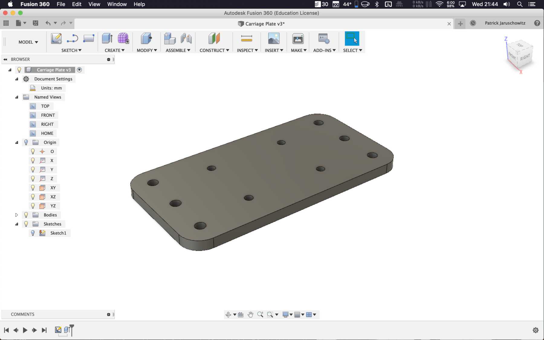
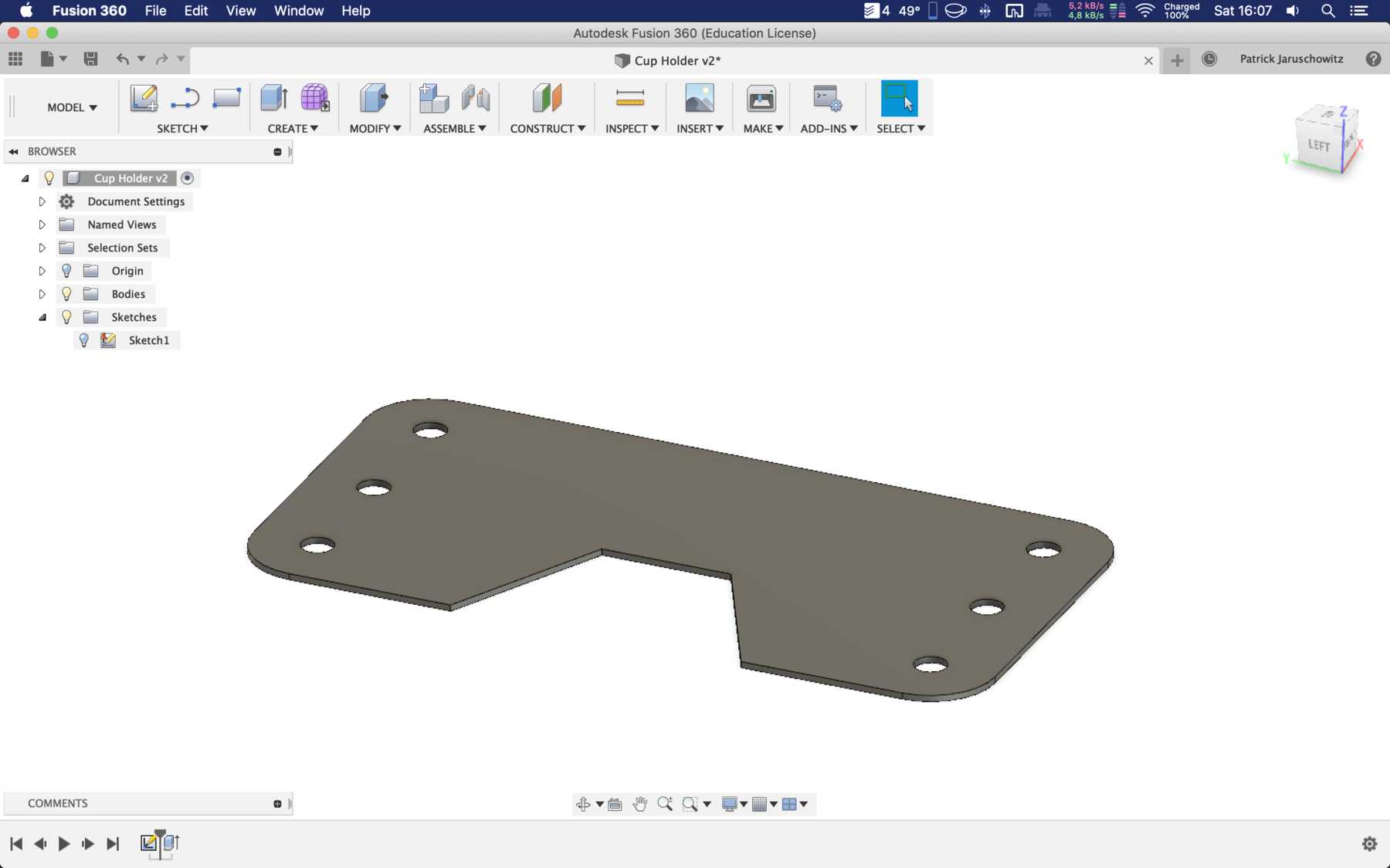
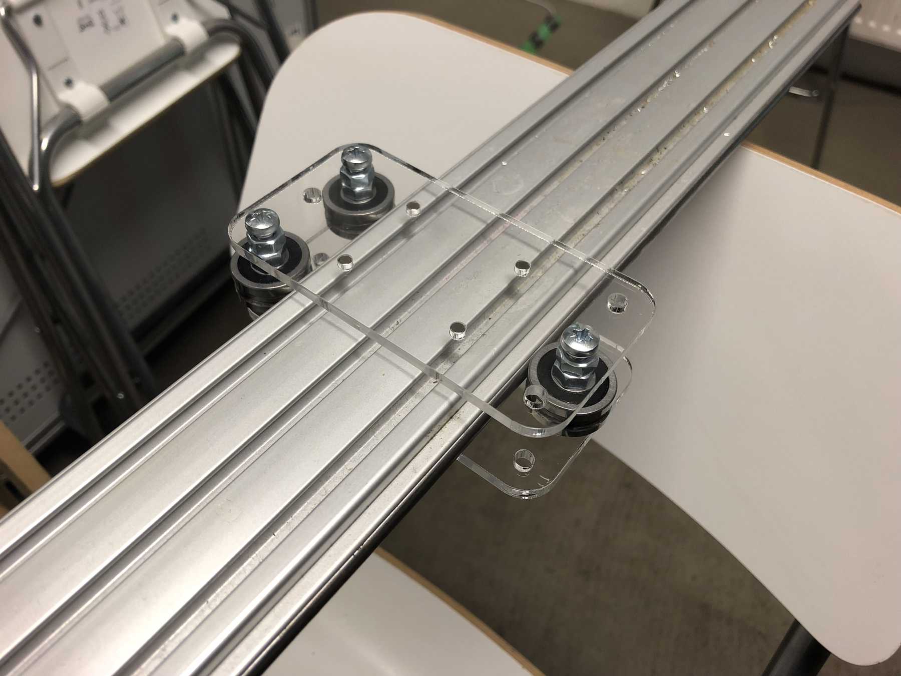
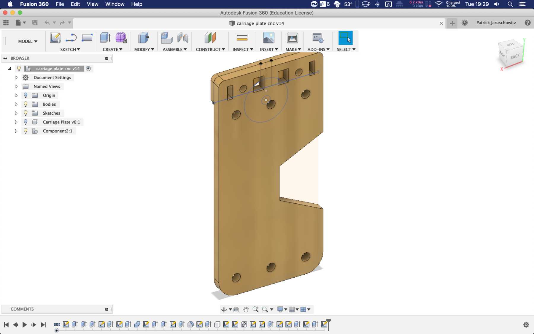
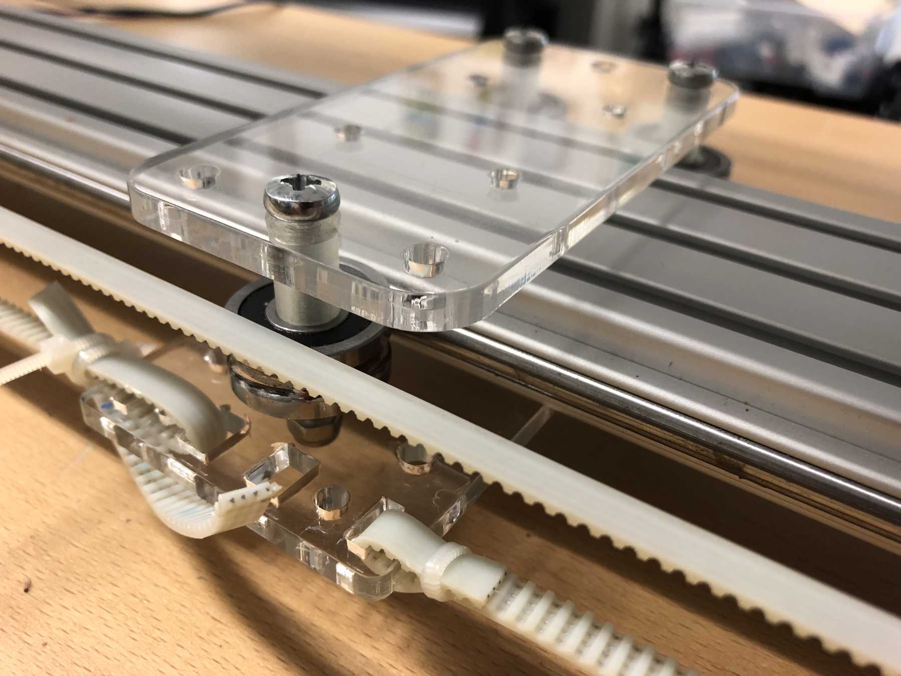
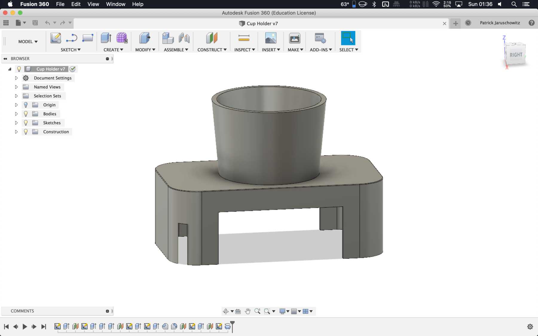
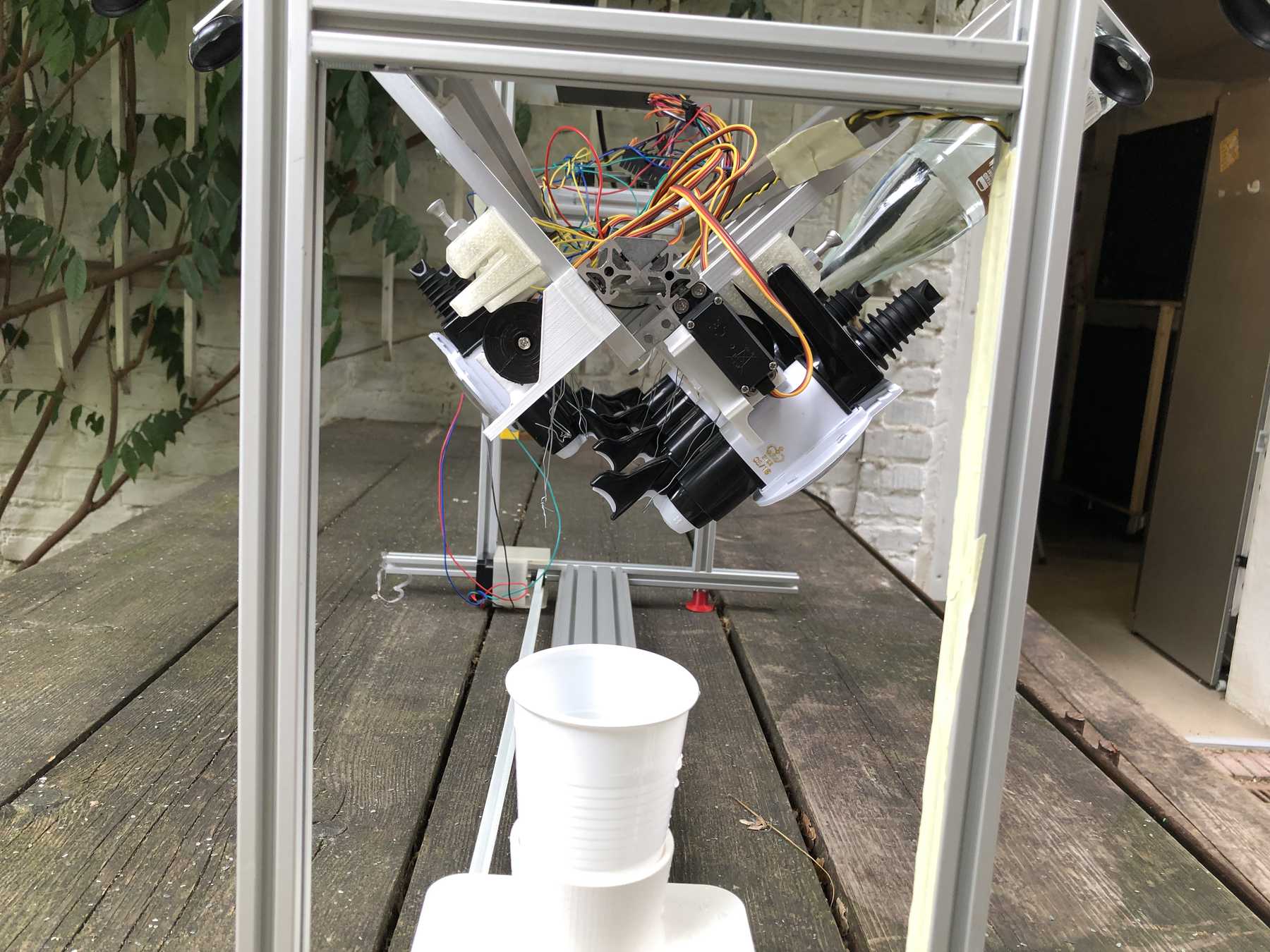
Designing the cup holder and the carriage system
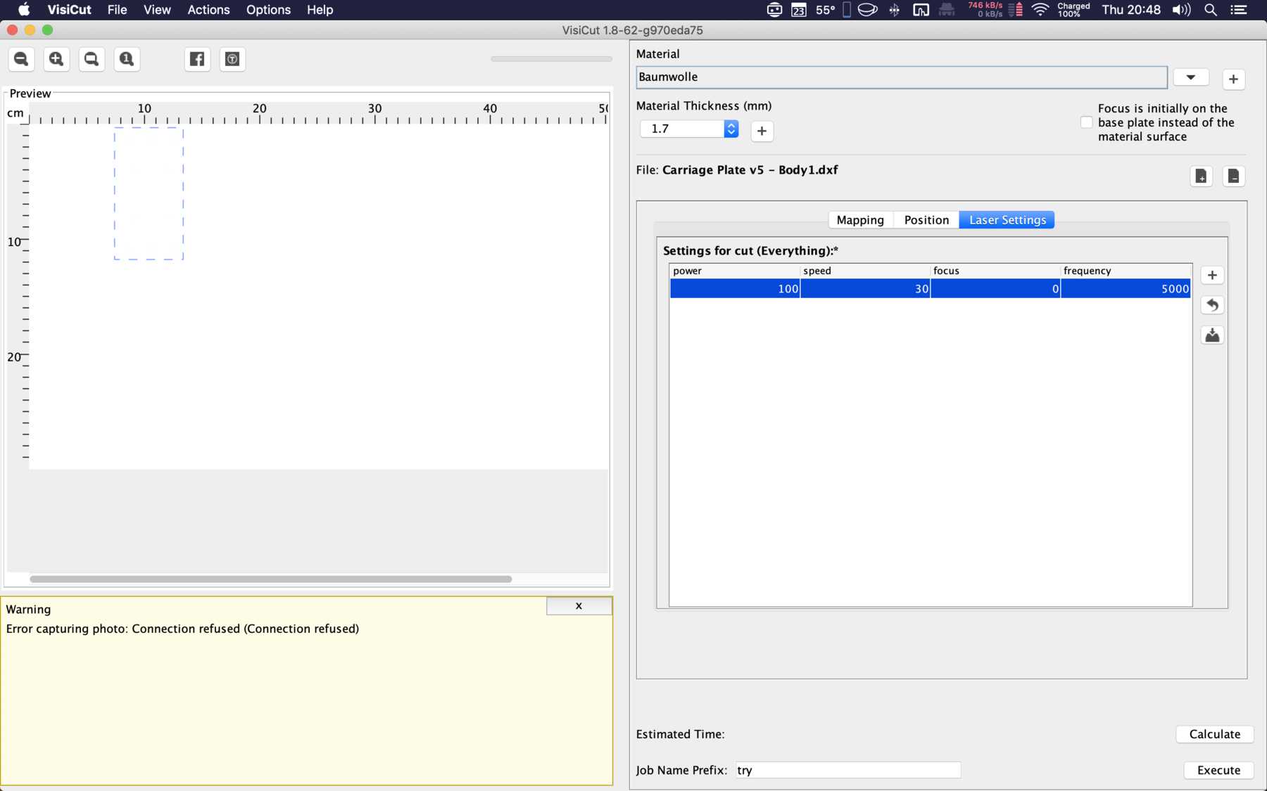
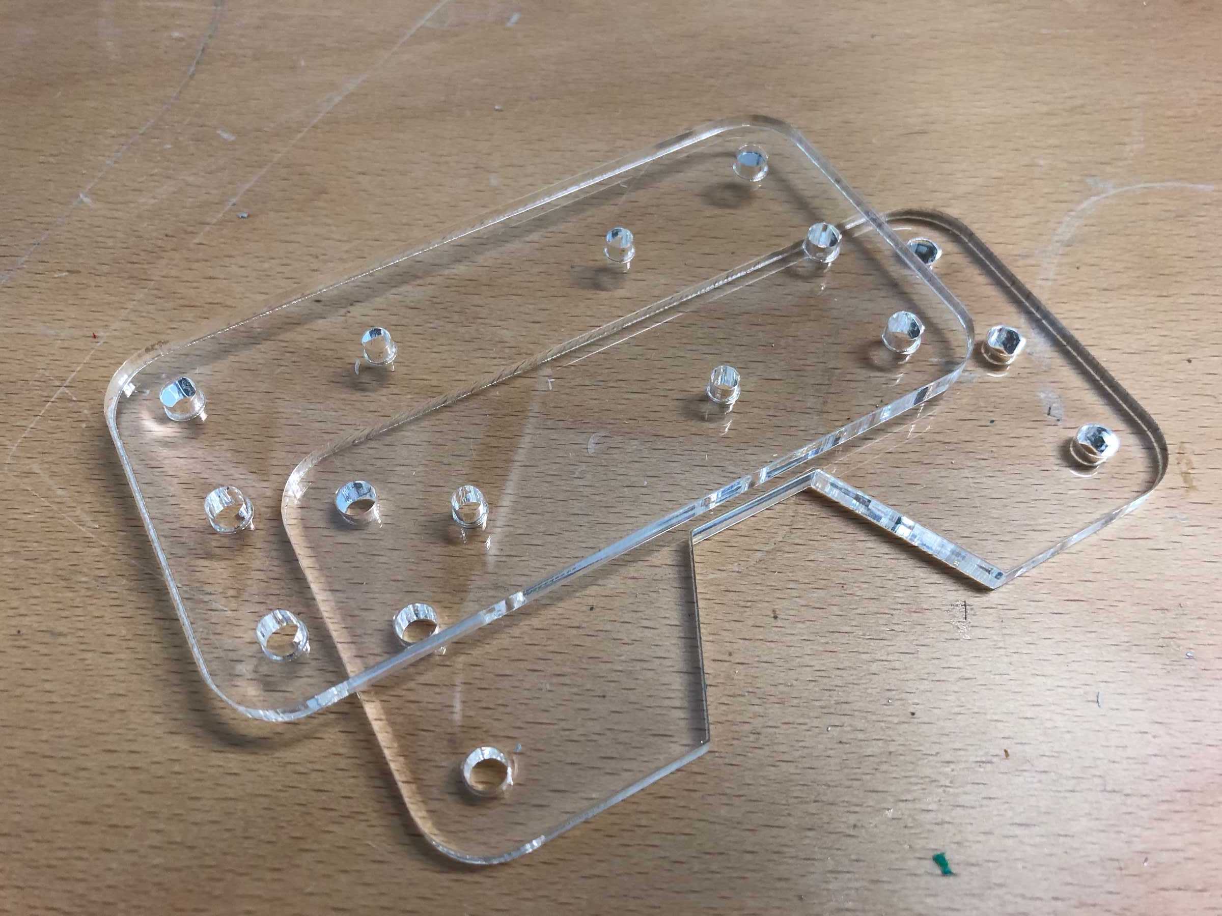
The cup holder should be constructed in such a way that it is modular and can be adjusted to different heights. Ideally with insert pads that would make the whole thing easier. The design was based on rollers that are guided. The carriage system is made of acrylic glass with a laser cutter. There were a few adjustments to the design, as you can see on the pictures. The magnets are embedded and milled so that they fit exactly and are jammed. For future events you can then simply clean the dirty cup holders. At least that’s the idea. First I cut the acrylic glass so that the carrier system looks like this:
Everything was connected via screws, nuts and impellers.
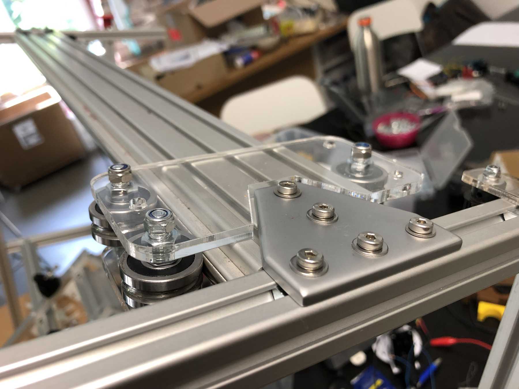
Later we noticed that it didn’t quite work with the belt. For this purpose we changed it as follows:
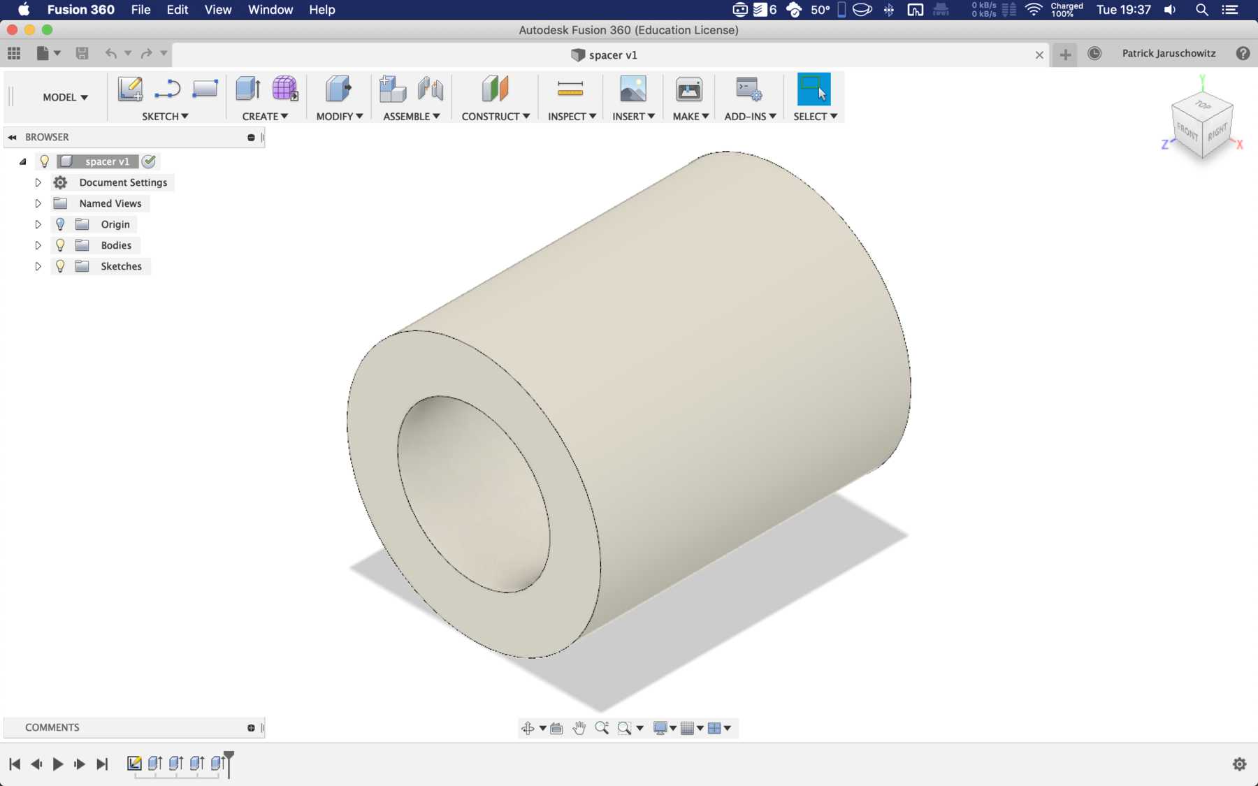
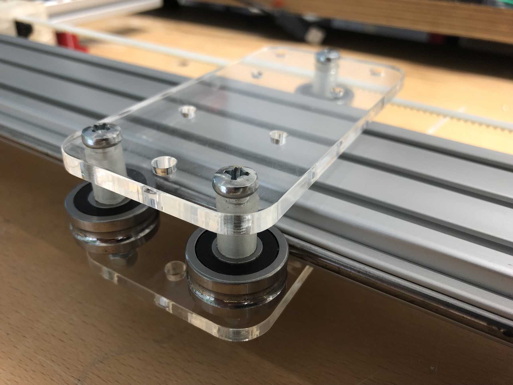
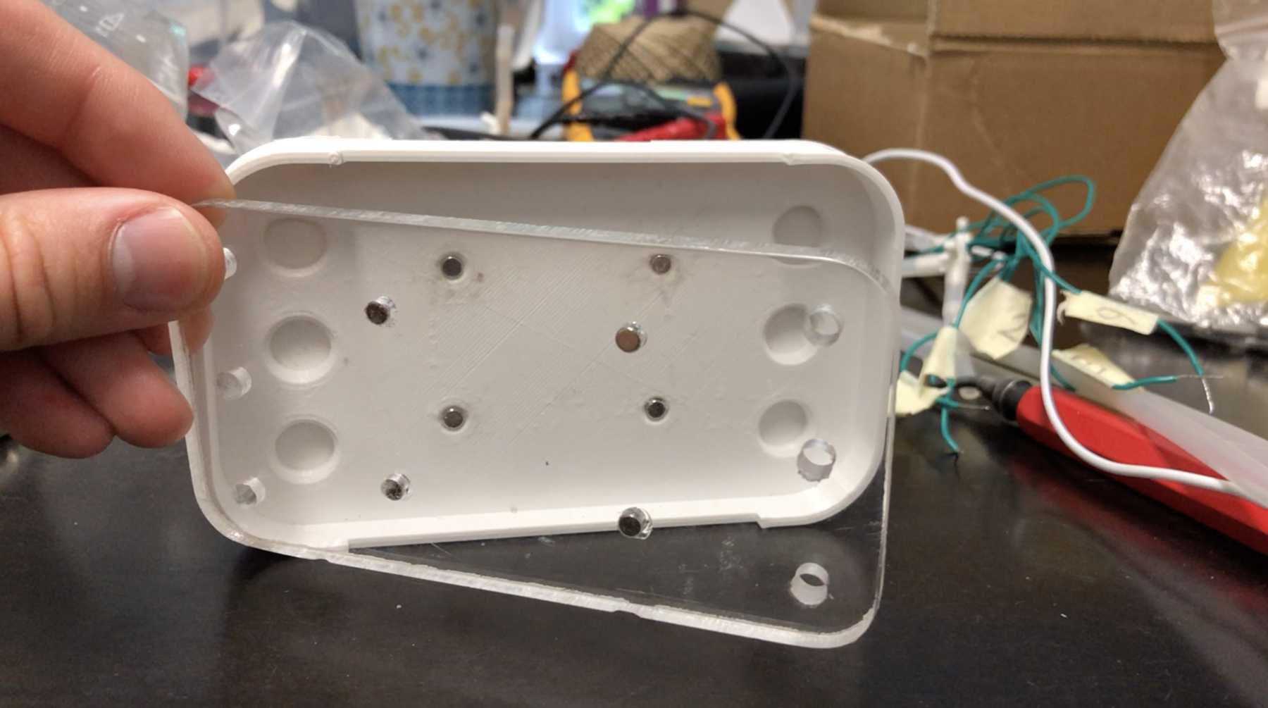
The modular system with cover and support plate is realized by magnets. We also created the spacers ourselves instead of using nuts. And this is how it looks with the lid:
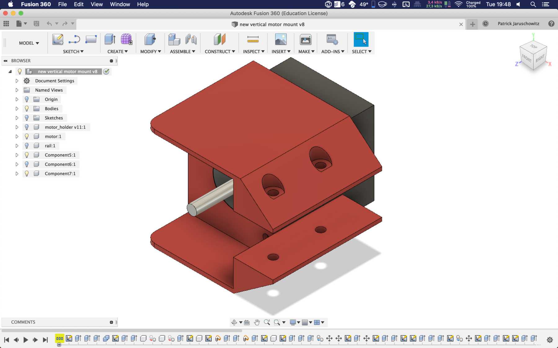
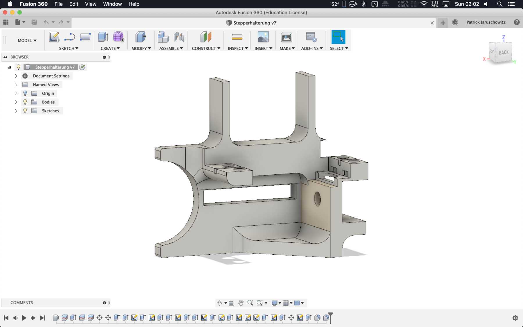
Mounting for the stepper motor
The mounting for the stepper motor was made of 5mm acrylic with the help of the laser cutter. It should be fixed to the profile with three screws and slot nuts.
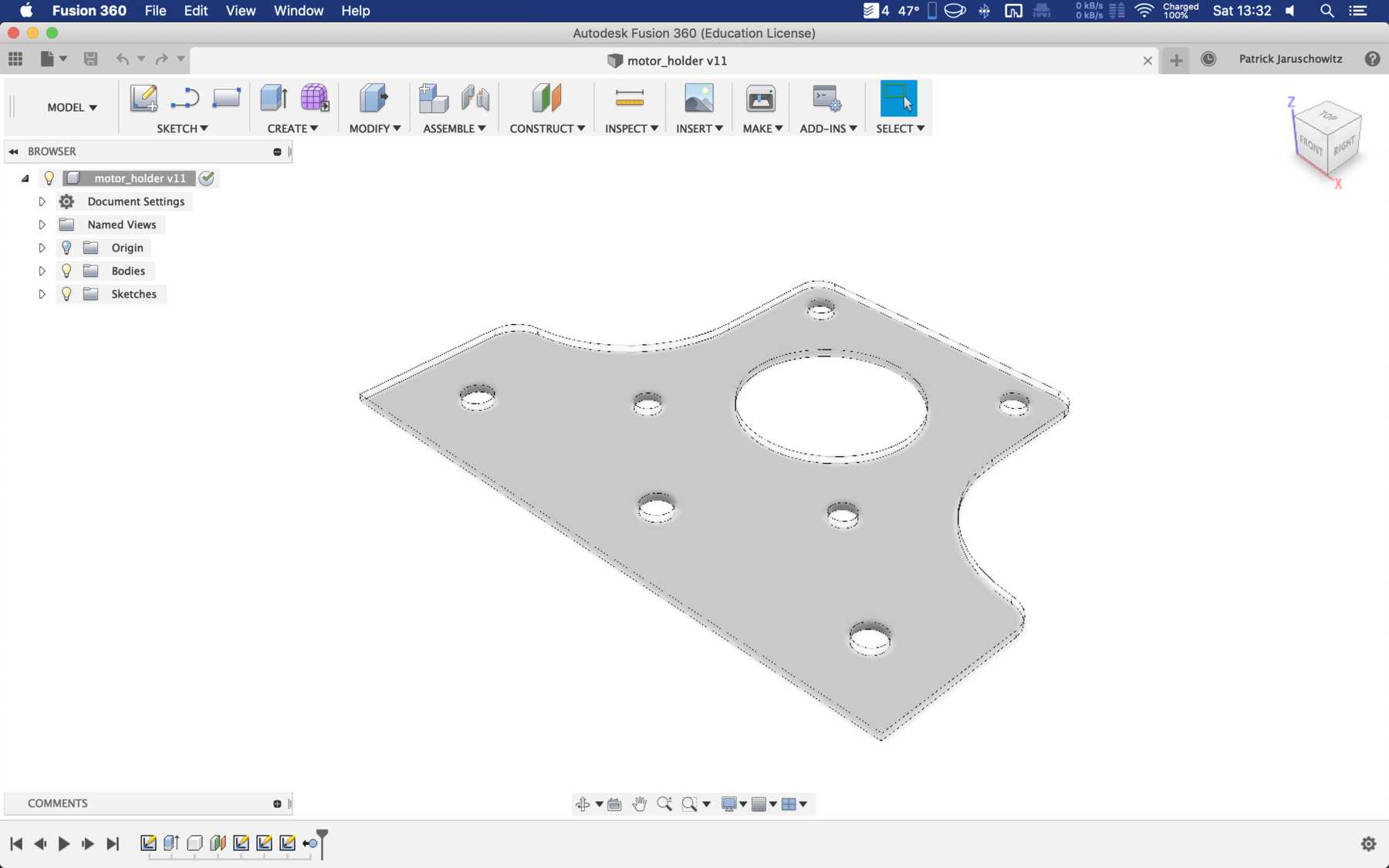
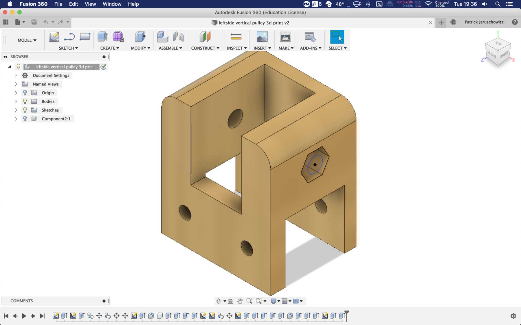
After some iteration the mounting changed:
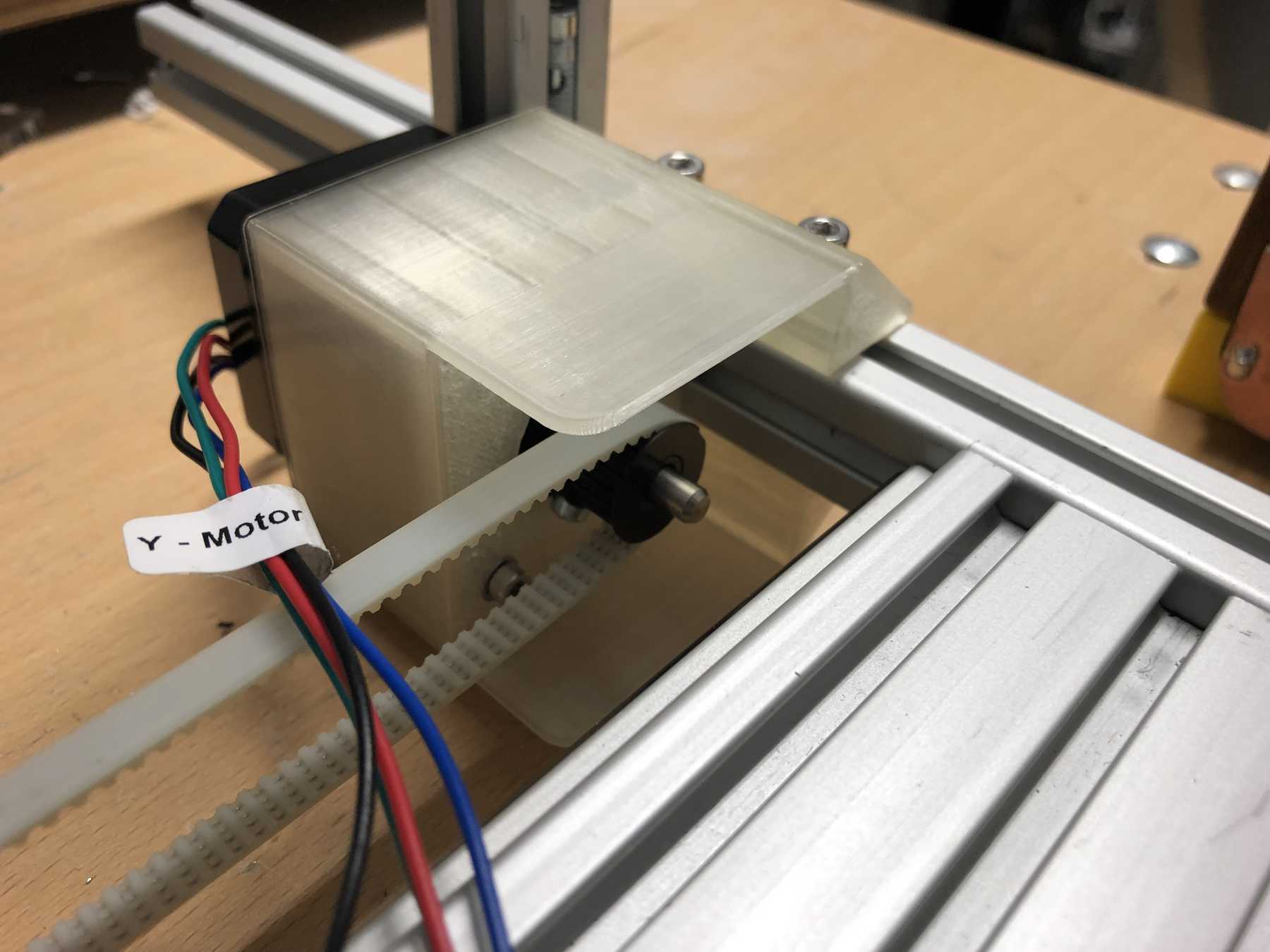
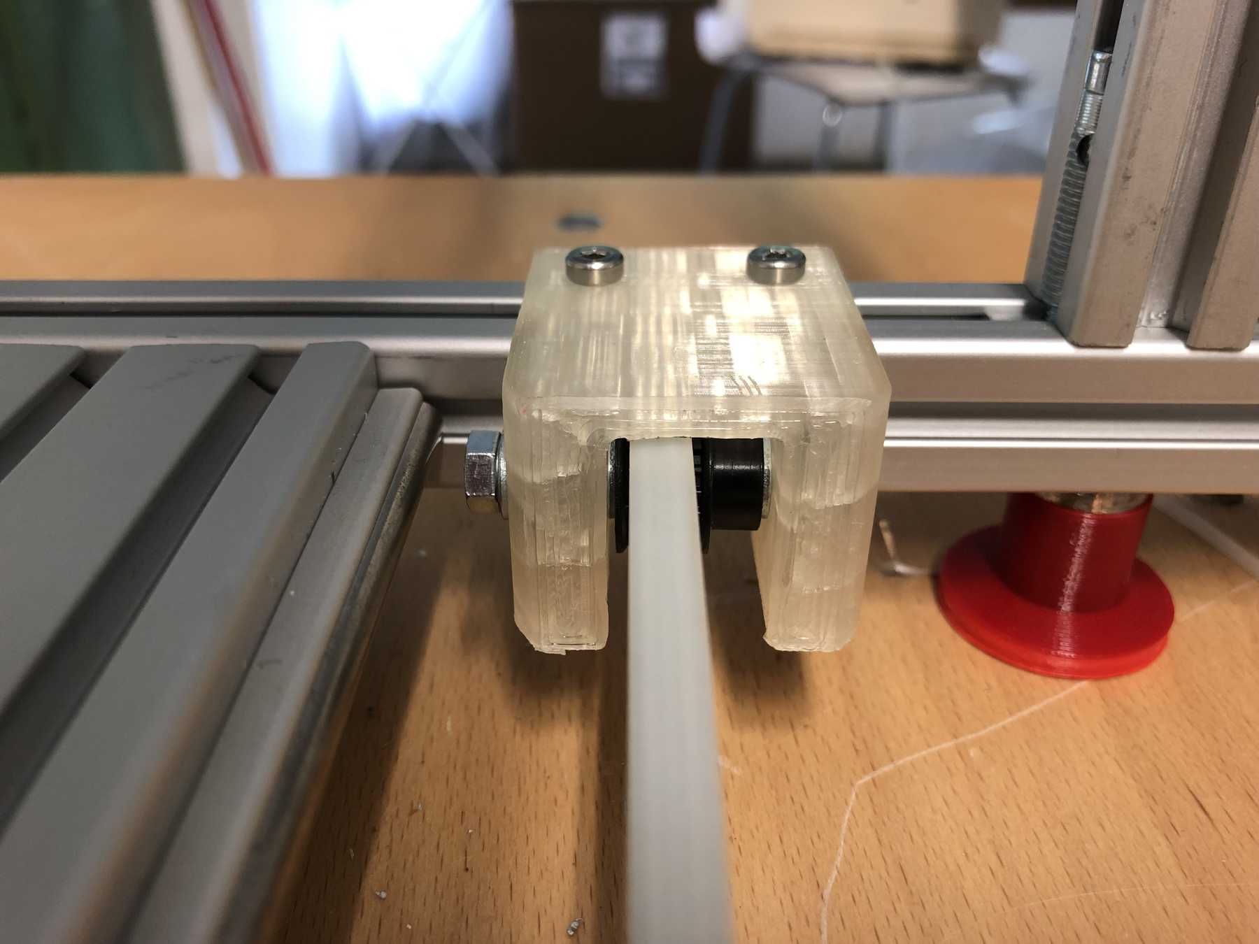
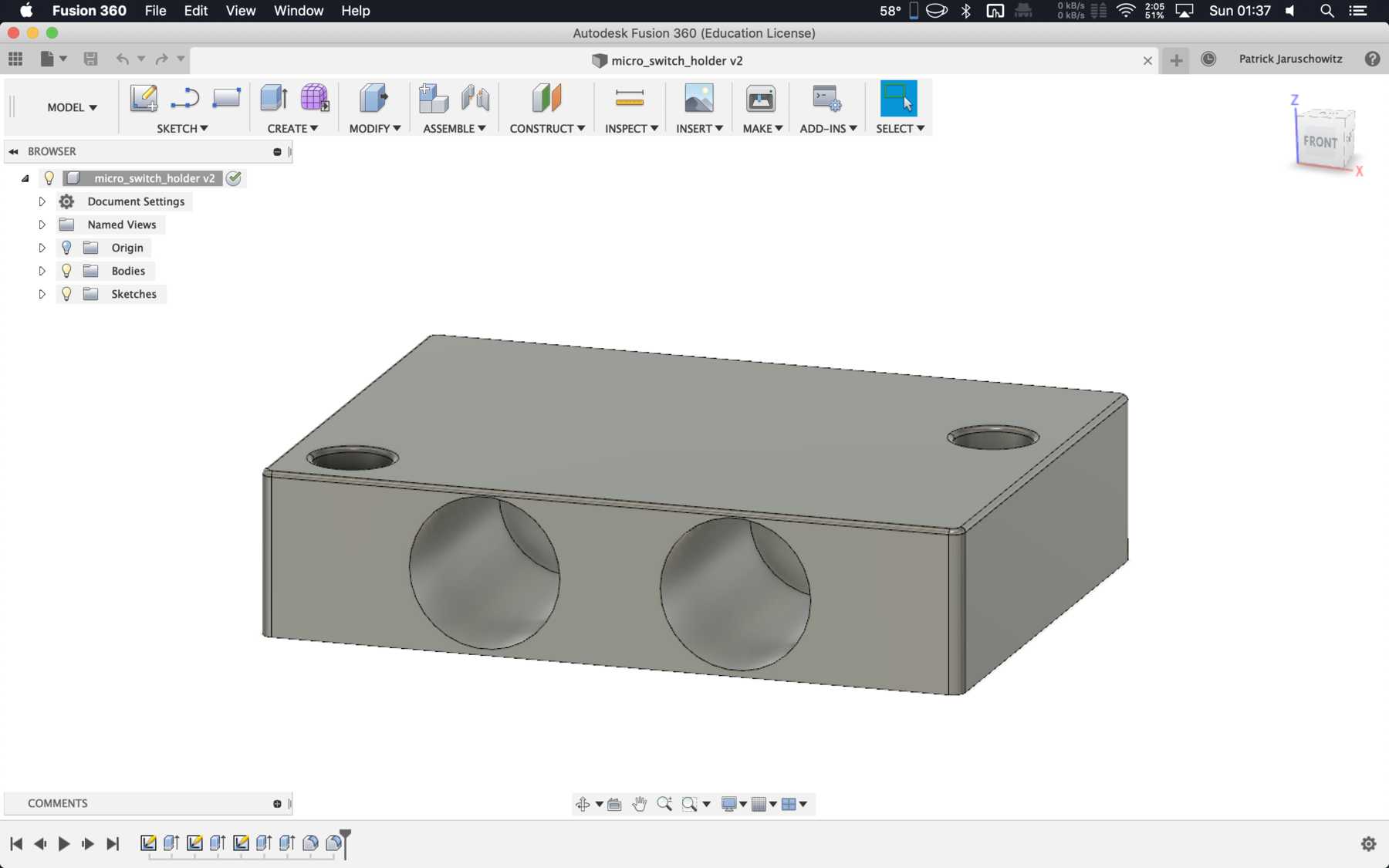
Mounting for the belt
On the other side we needed another mounting for the belt.
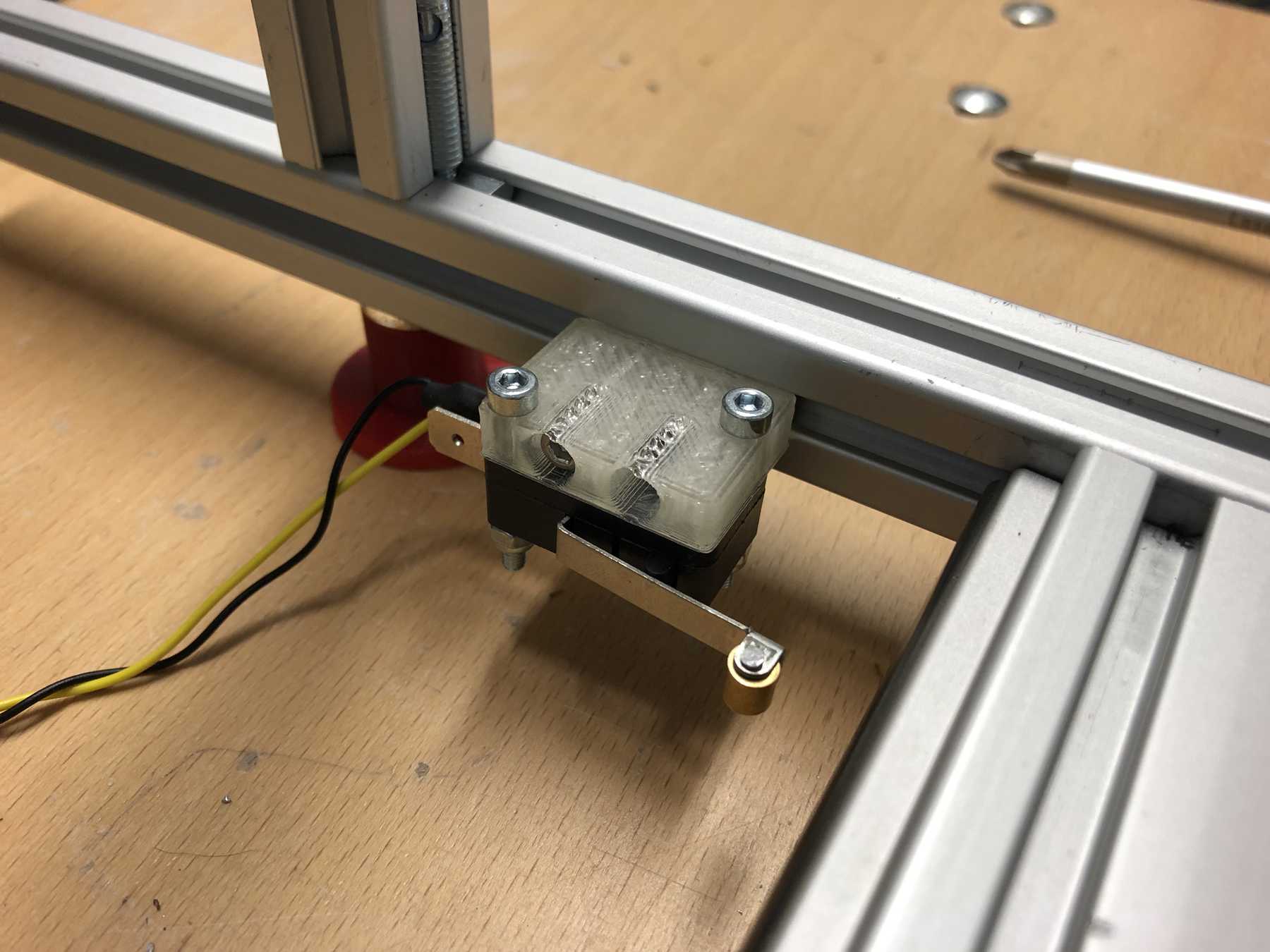
Micro switch
The Micro switch still had to be attached to a profile. The following design was sufficient:
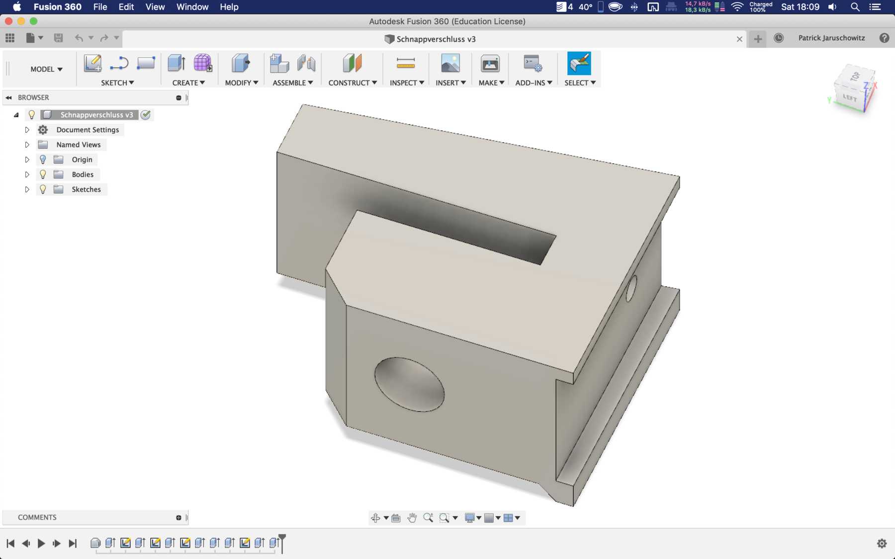
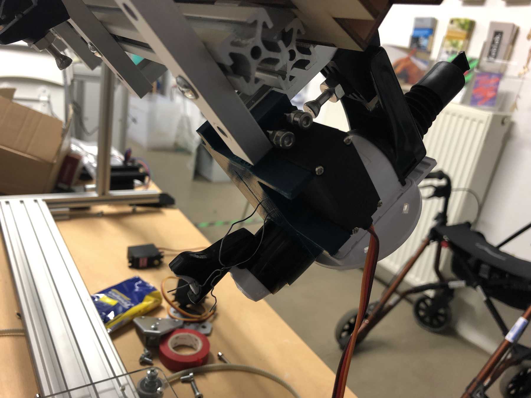
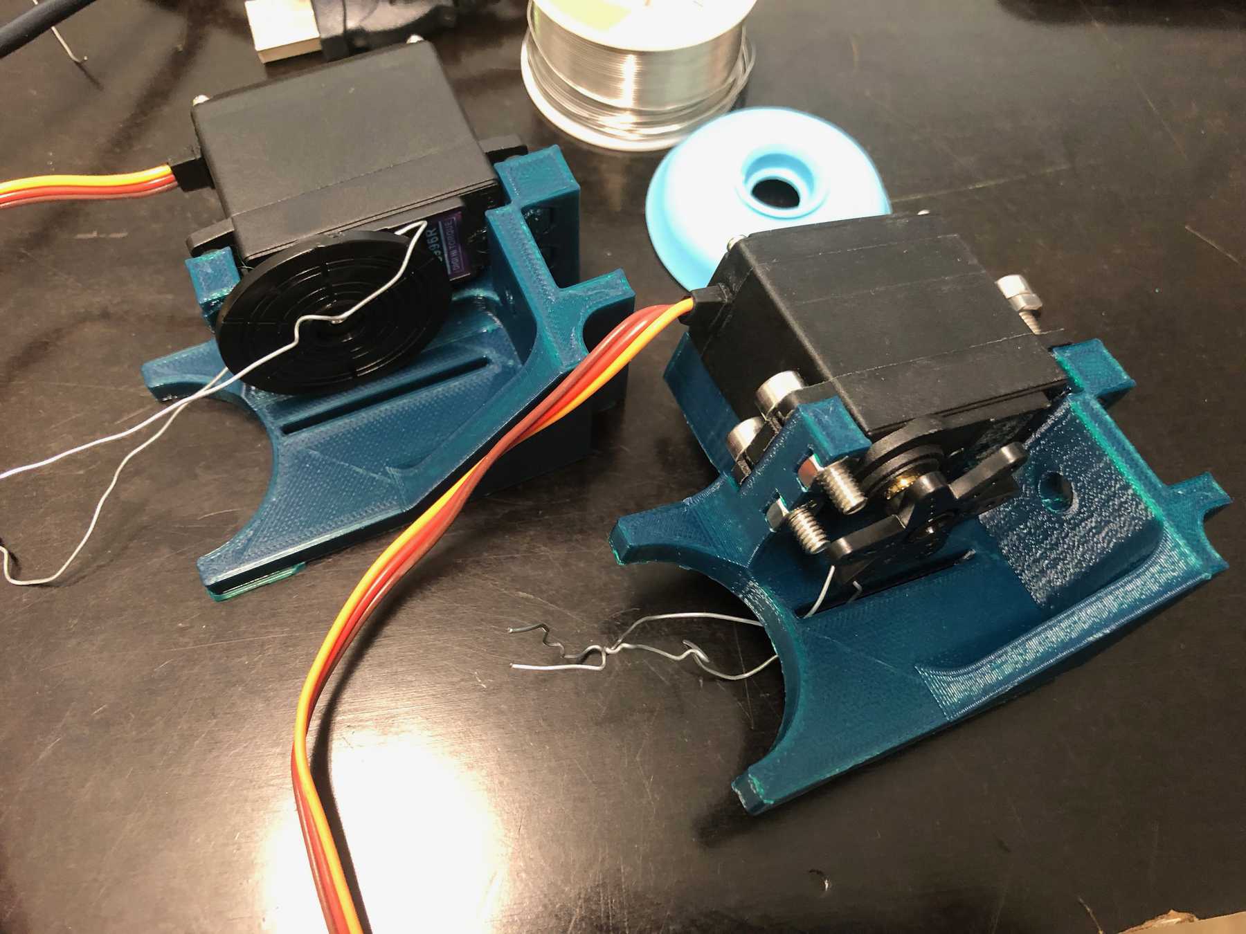
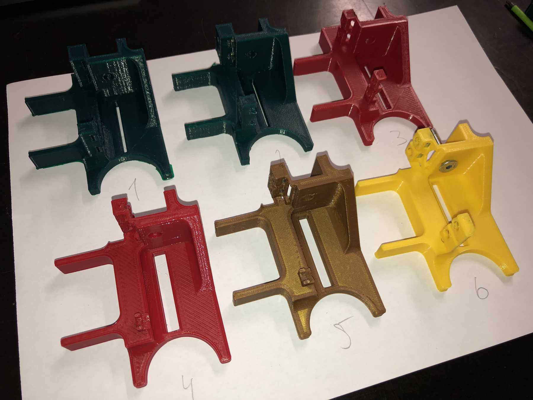
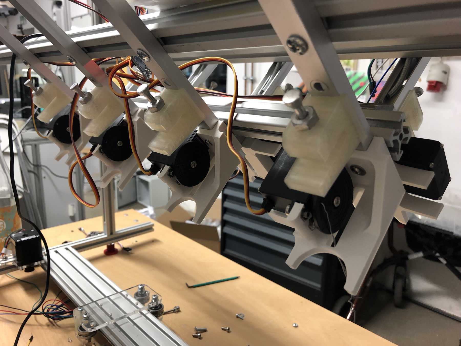
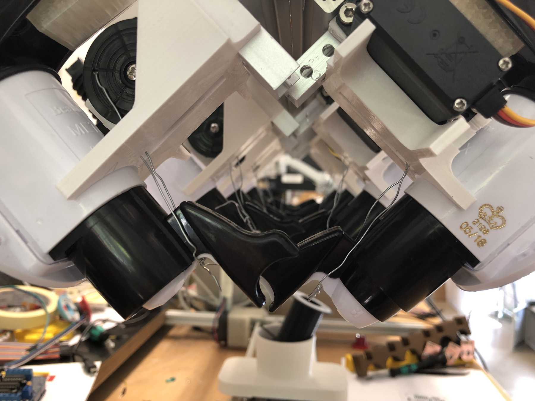
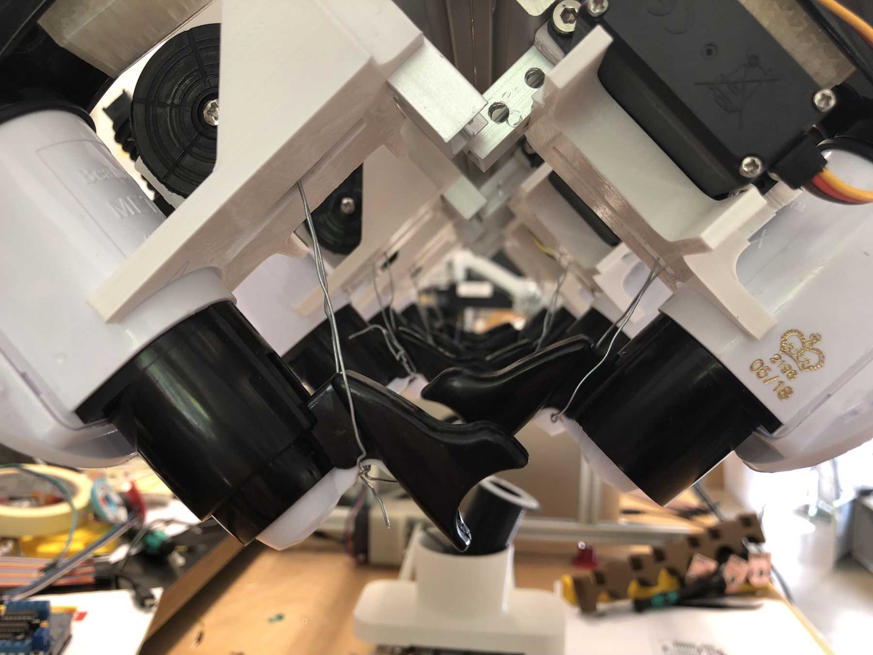
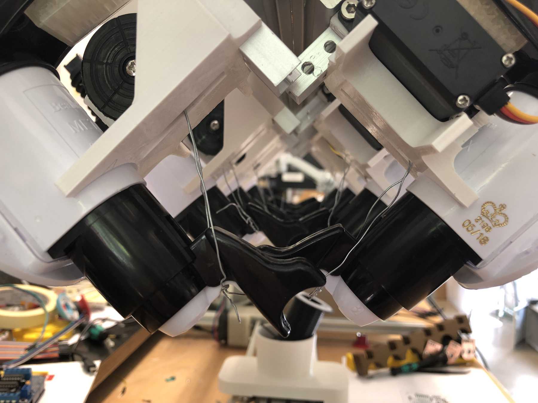
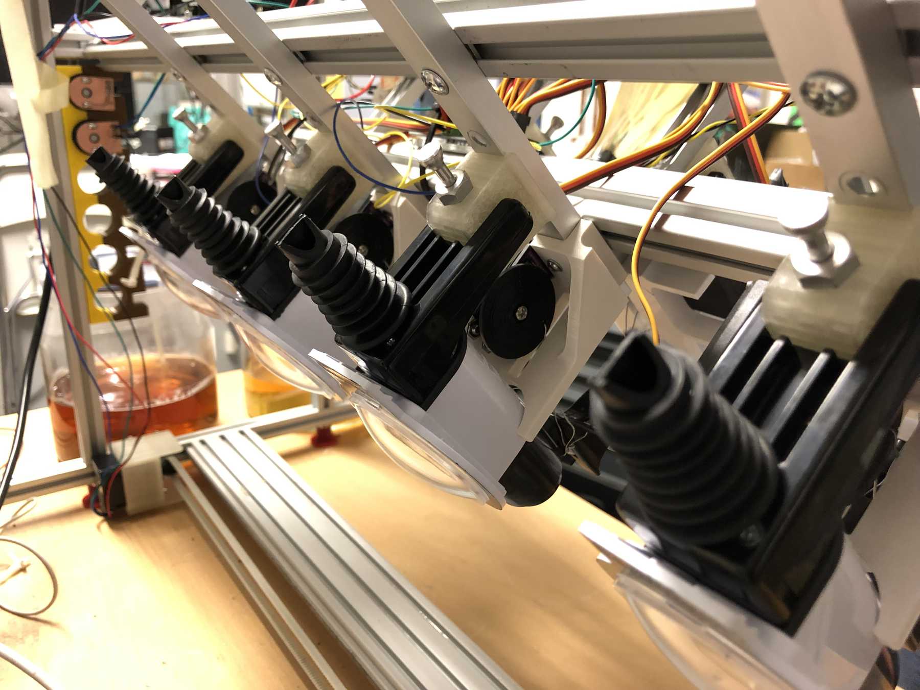
Designing the bottle holder
The next step was to design the bottle holder. The whole thing took countless iterations until everything actually worked. The difficulty was that sometimes only small details didn’t make it possible. Despite planning, you always overlook something in the fast track. Also the integration of the servo, the proper gear and a possible mechanism over a wire are shown. We will see whether the wire is a long-term solution.
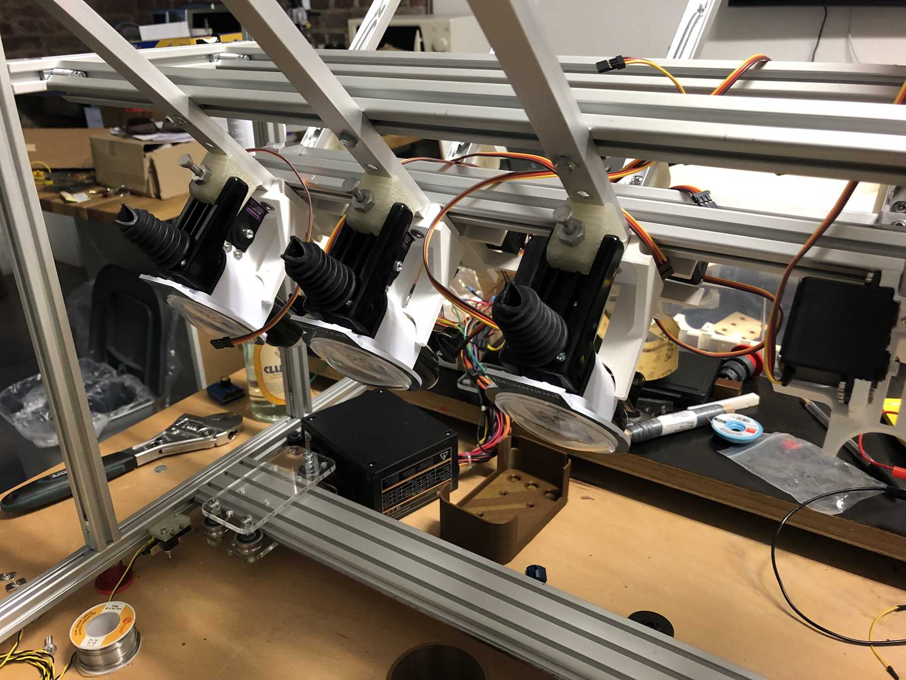
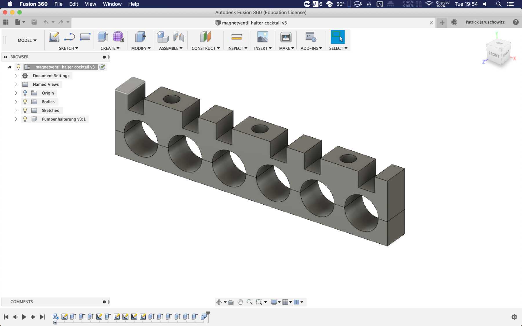
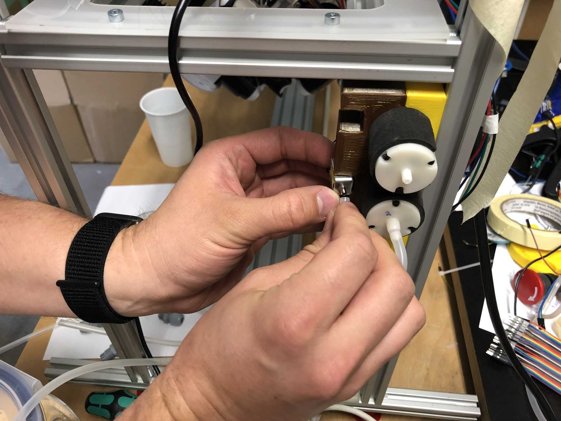
Mounting for the pumps
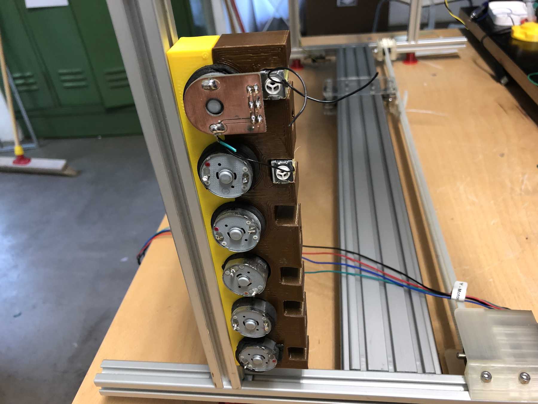
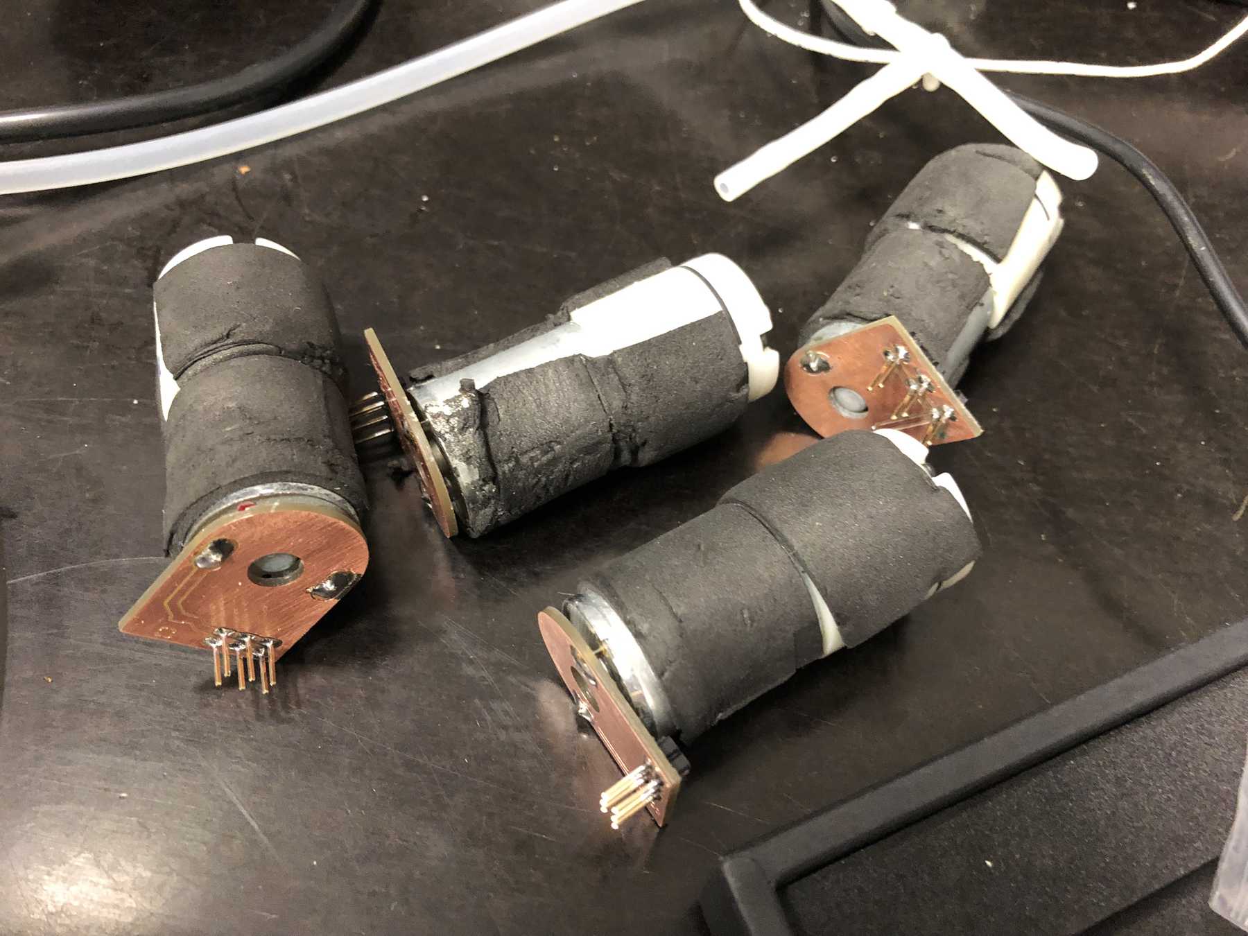
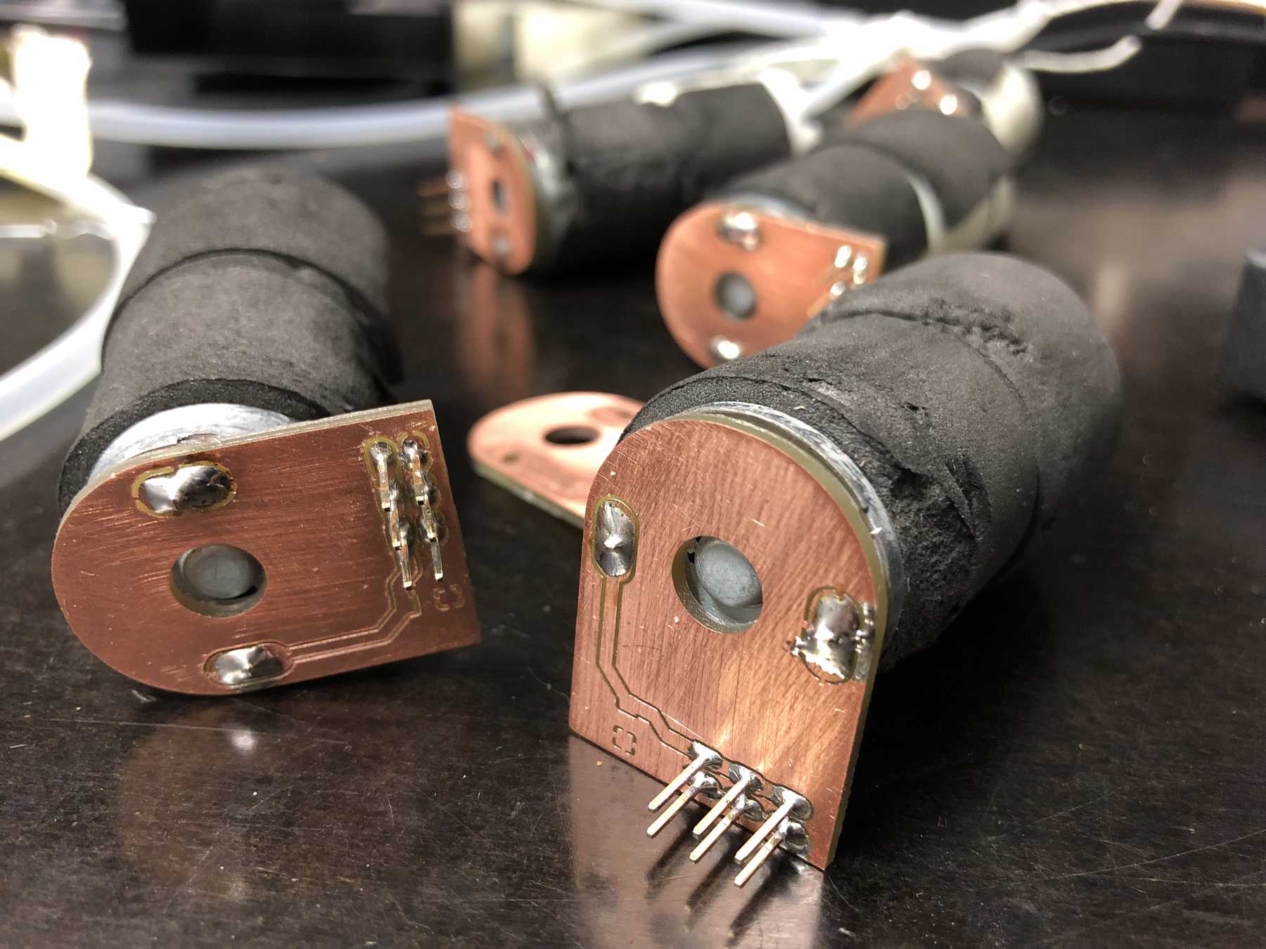
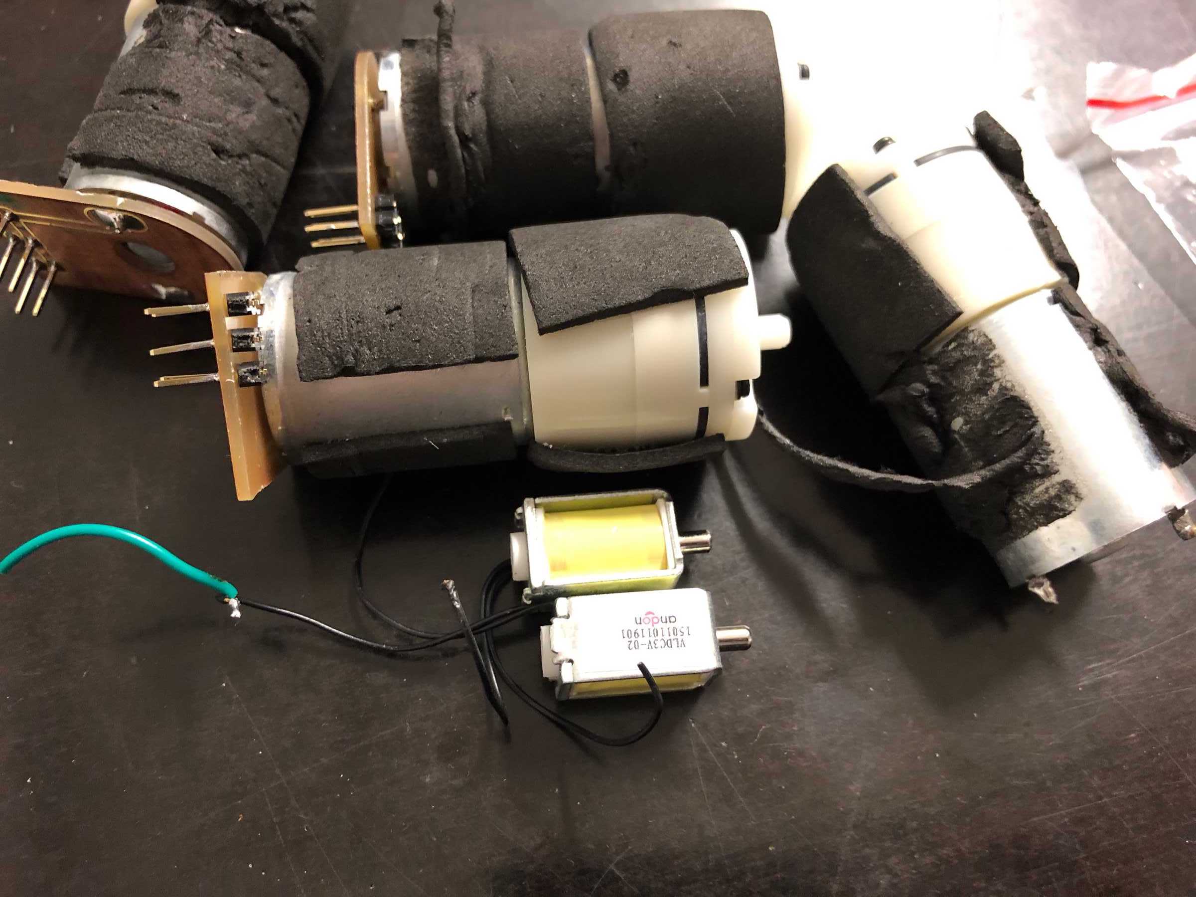
We have removed pumps from old blood pressure measuring devices from an earlier event. Finally we can use them in a cocktail machine. Therefore we disassembled everything and built the following mount.

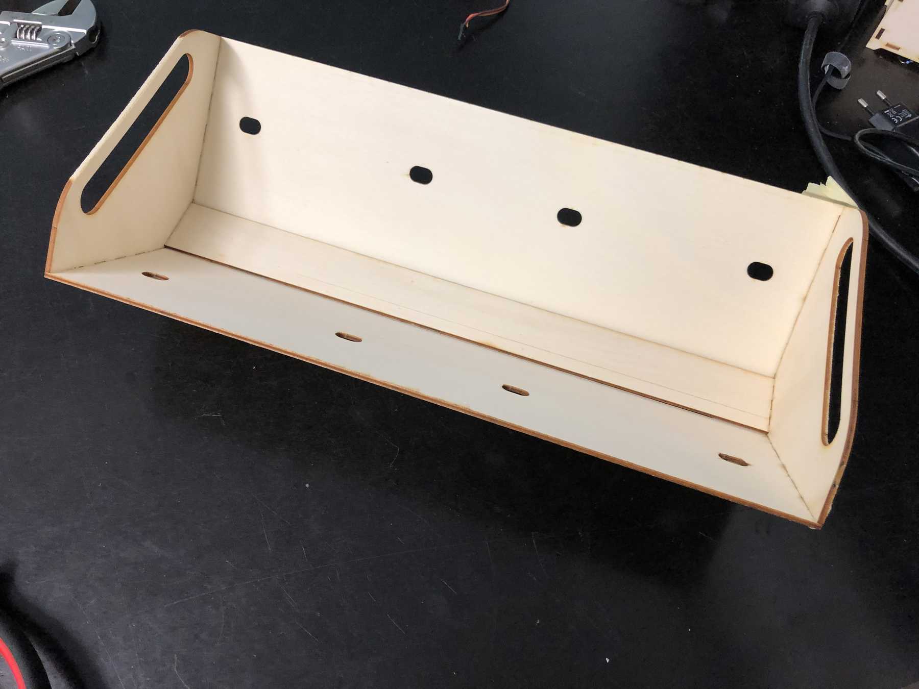
Compartment for electronics
The electronics should be placed in a simple box in the prototype. We designed something where you can just put the electronics on top. Here are some pictures:
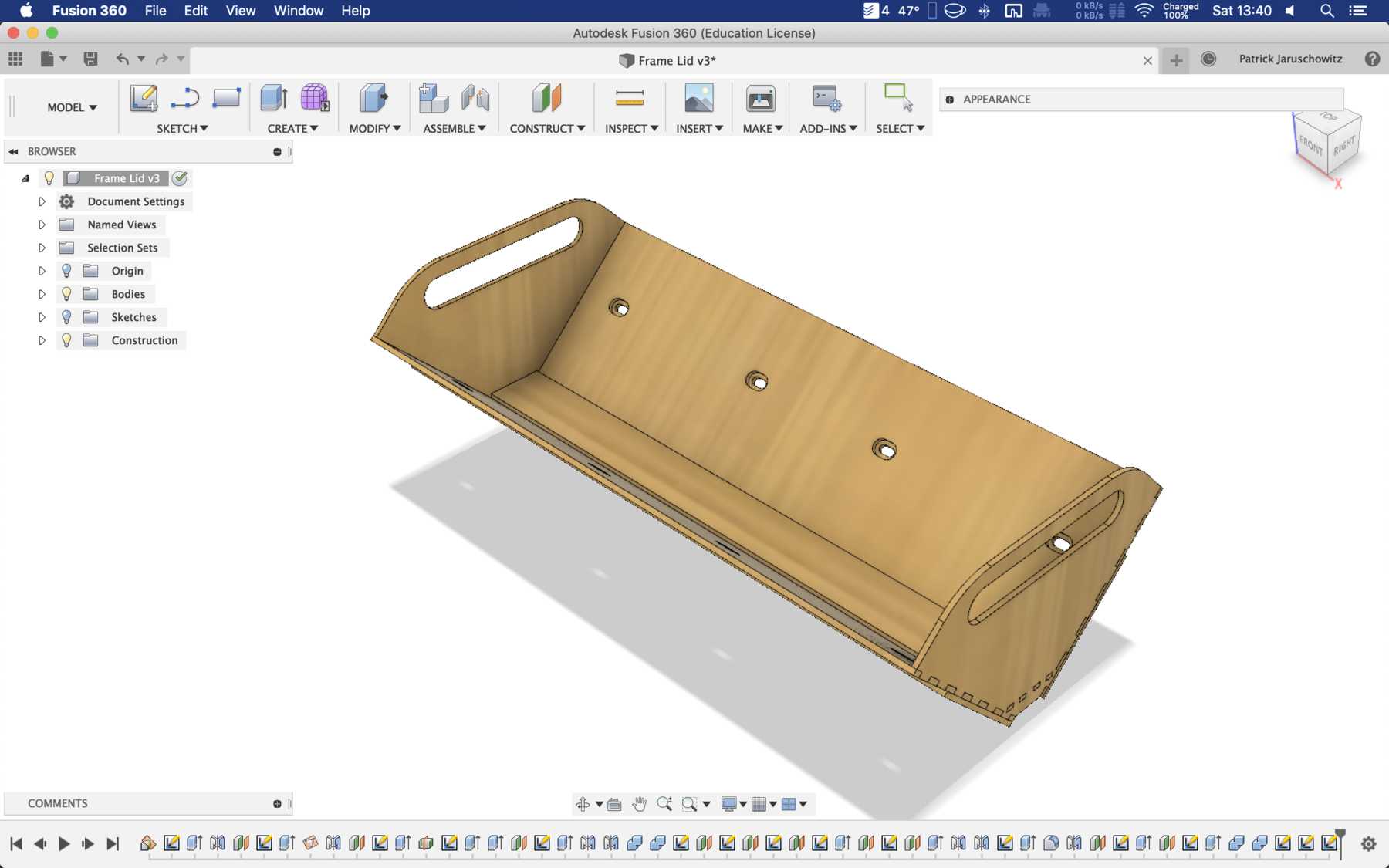
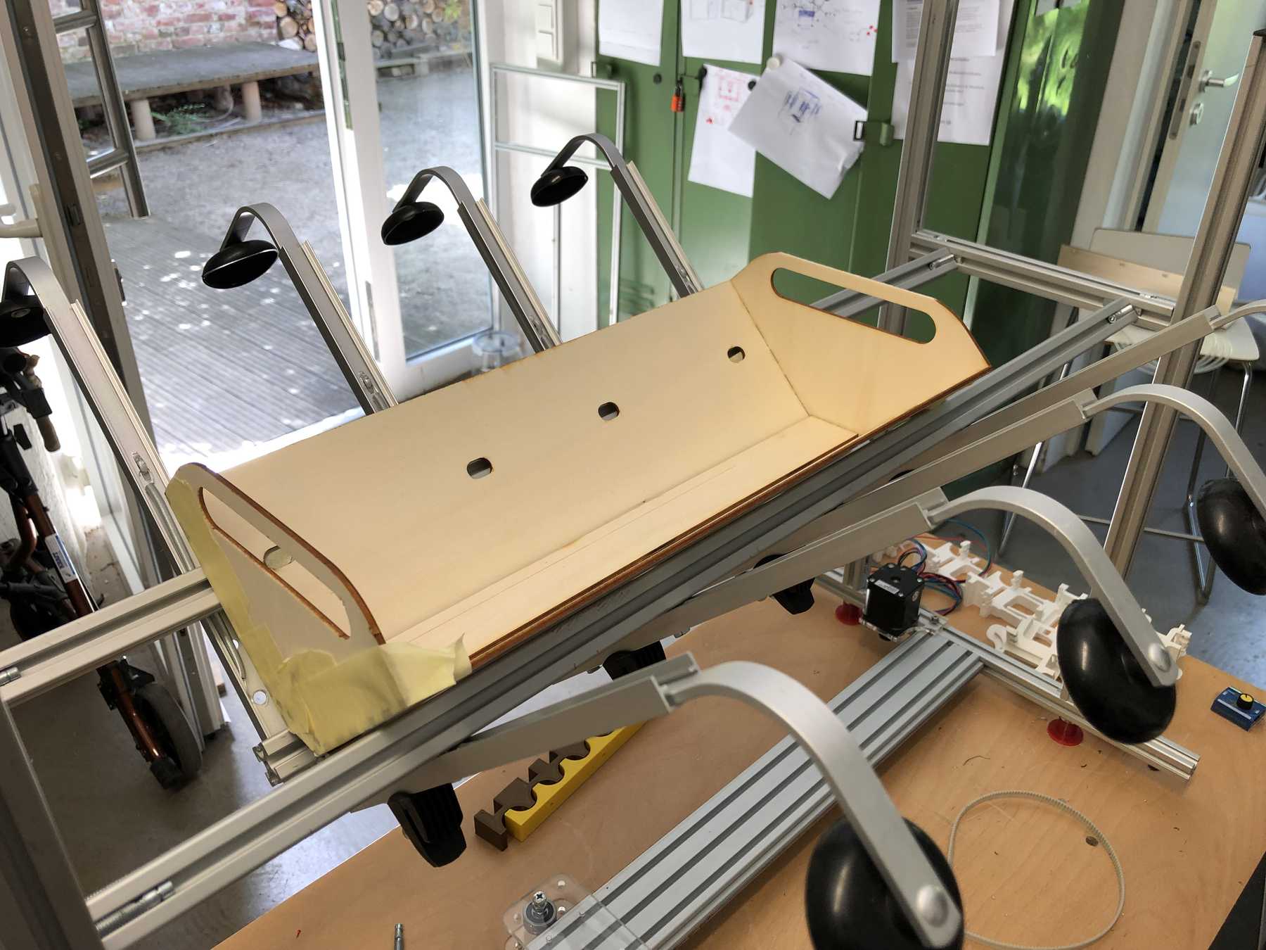
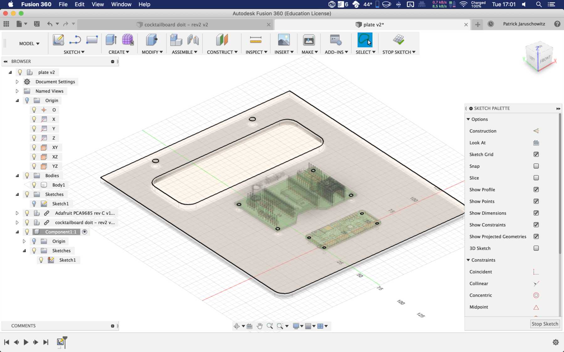
Later we changed it into the following design:
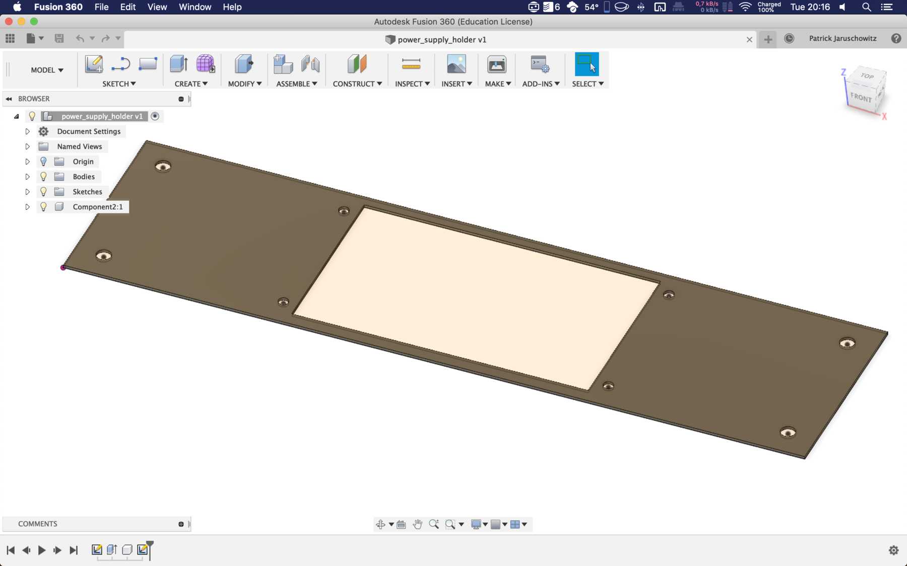
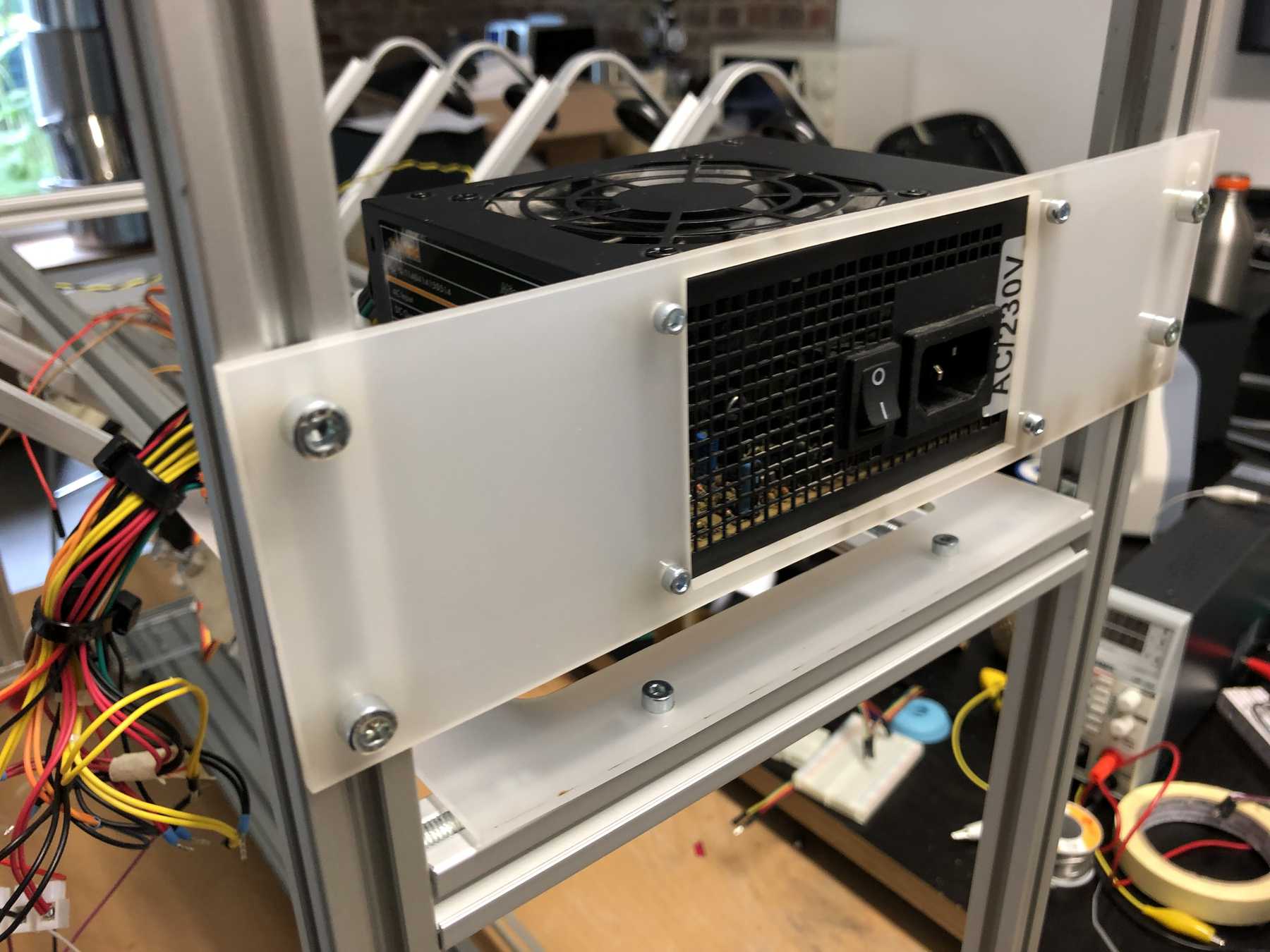
Mounting for the power supply
Last but not least we needed a holder for the power supply.
Conclusion: Little time, a lot of work, but a very nice result. After the Fab Academy, some small things can and will be optimized.
Finally, a video documenting the construction:
Here you can download all the files as STEP files:
Cocktail machine files
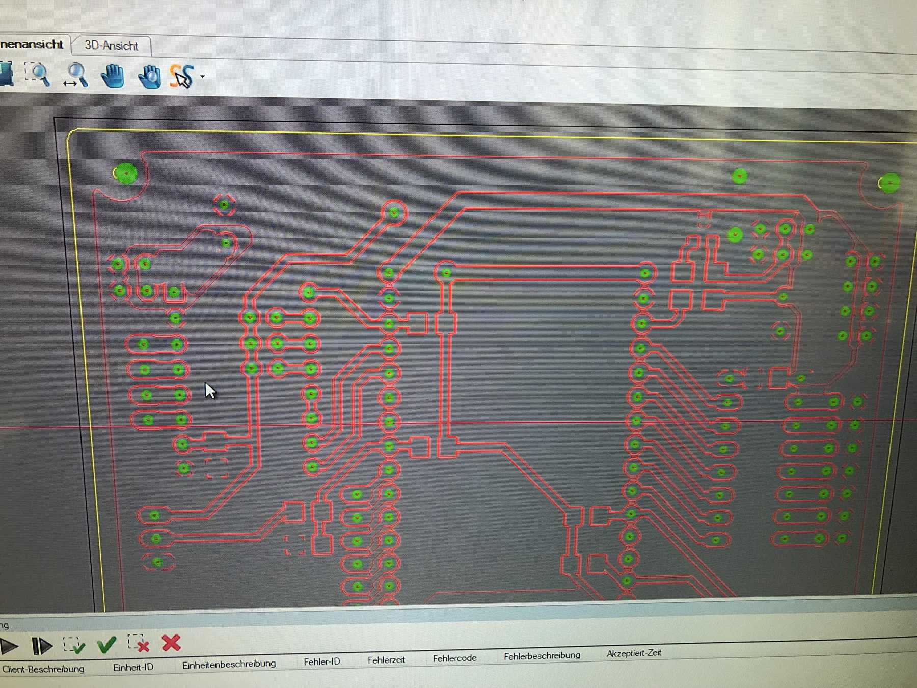
Designing the circuit board
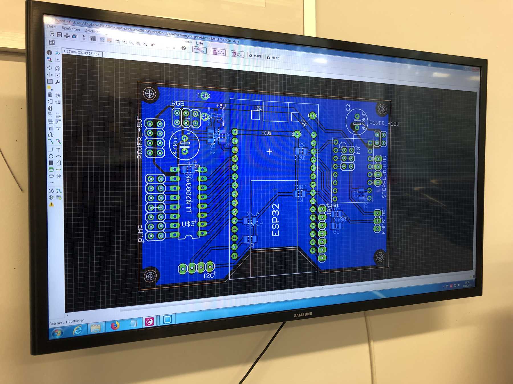
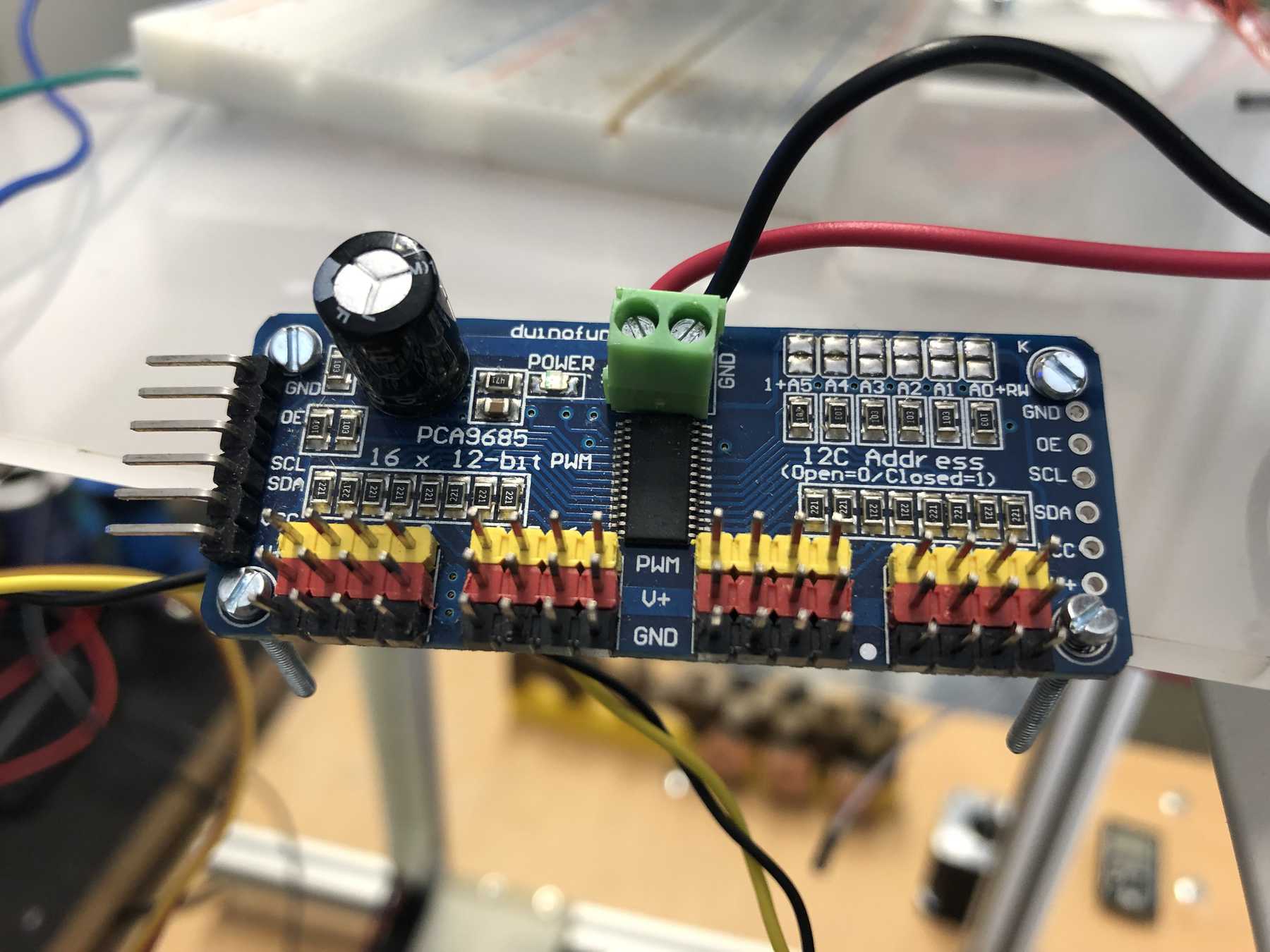
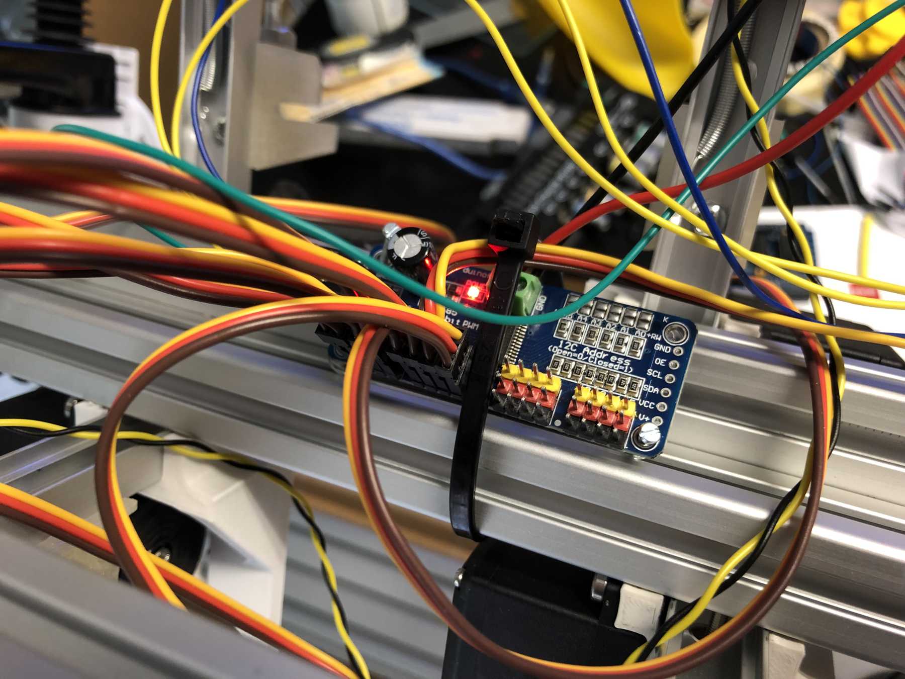
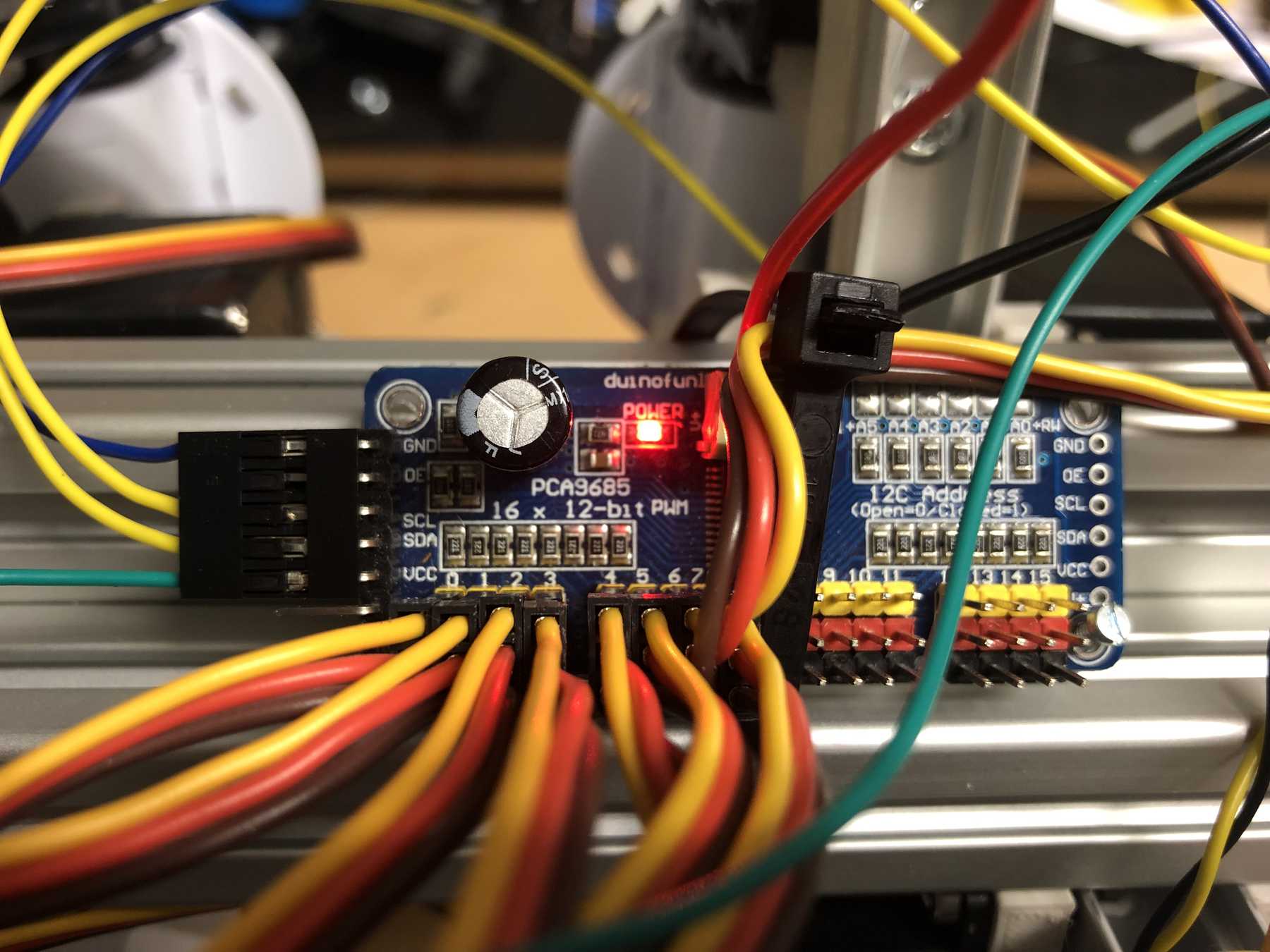
First, we reviewed all the requirements the board needed. We wanted to use a DOIT Esp32 DevKit v1 board for control. This should address the stepper motor, the pumps, the endstop, the servos and later the LEDs. To control the servos we use the Adafruit 16-Channel 12-bit PWM/Servo Driver - I2C interface - PCA9685 via I2C for PWM control, so our PWM driver. First we tried the whole thing out one by one and then we started with the design. At the beginning we developed the following:
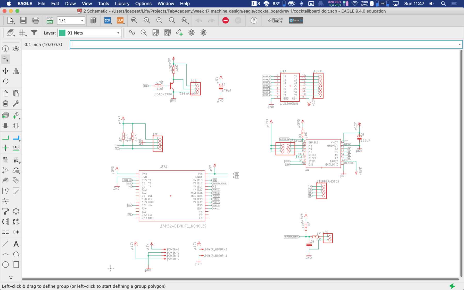
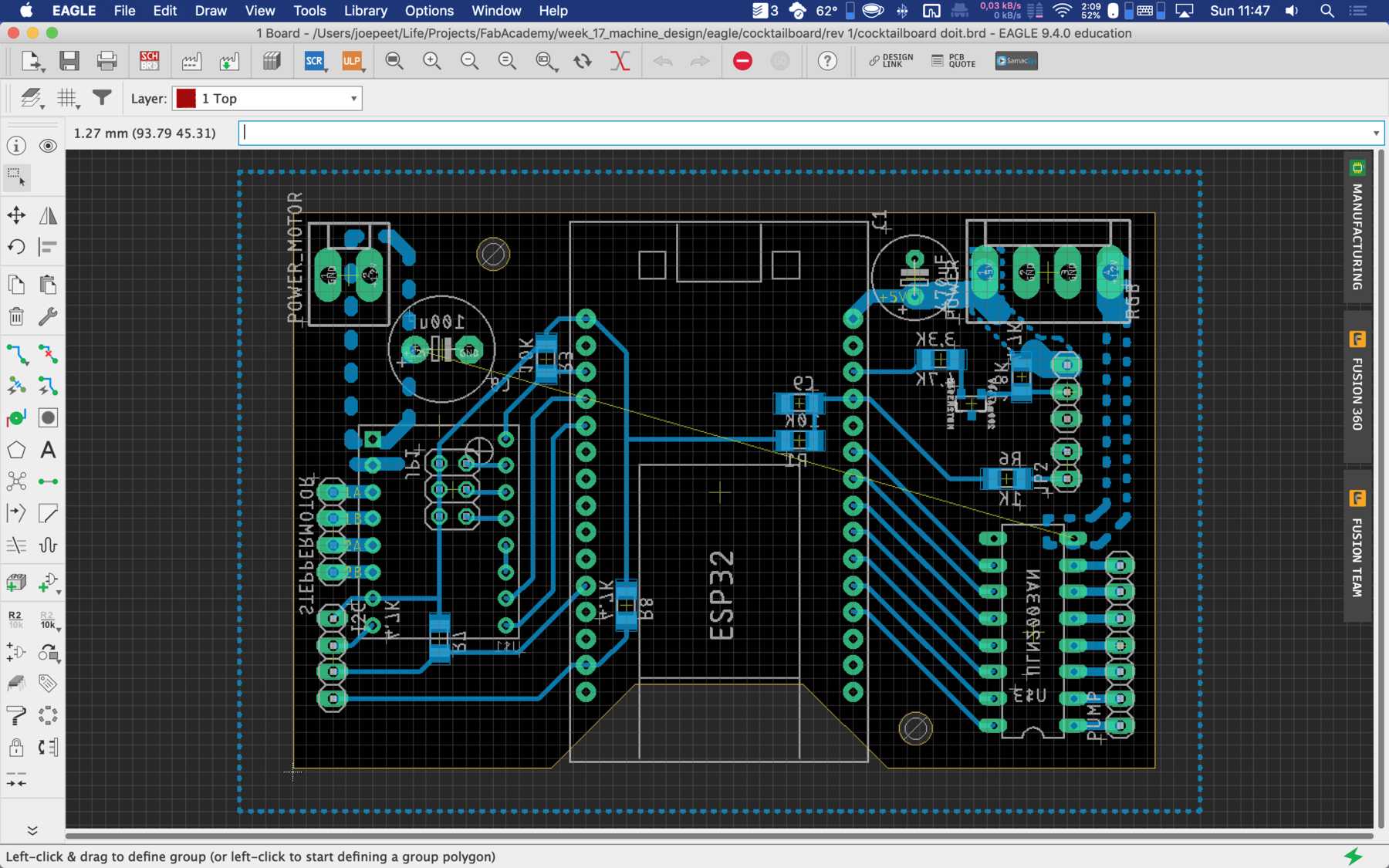
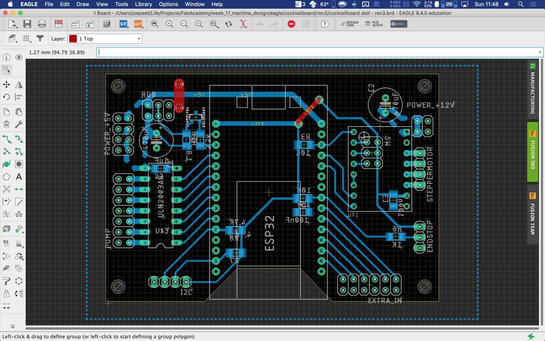
During the first iteration different arrangements were changed. Like some components were on the wrong side.
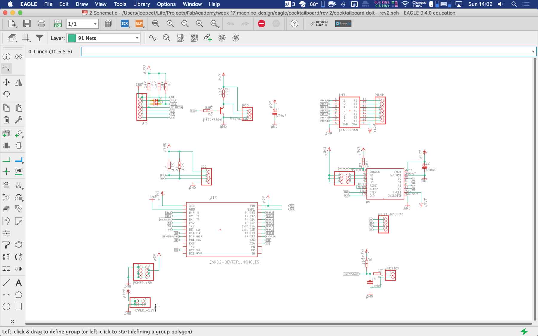
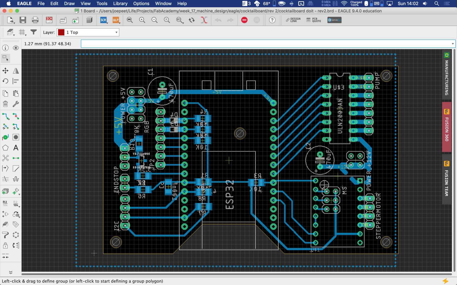
For the second iteration we had to use the PINOUTS, which you can really use. Due to the first iteration there were design changes which were reflected in the PIN mapping. Next time we’ll pay a lot of attention to which PINs actually support which functions.

The final parts list was as follows:
| Qty | Value | Device | Package | Parts | Description |
|---|---|---|---|---|---|
| 1 | PINHD-1X3 | 1X03 | ENDSTOP | PIN HEADER | |
| 2 | PINHD-1X4 | 1X04 | I2C, STEPPERMOTOR | PIN HEADER | |
| 1 | PINHD-2X2 | 2X02 | POWER_+12V | PIN HEADER | |
| 2 | PINHD-2X3 | 2X03 | MS, RGB | PIN HEADER | |
| 1 | PINHD-2X4 | 2X04 | POWER_+5V | PIN HEADER | |
| 1 | PINHD-2X6 | 2X06 | EXTRA_IN | PIN HEADER | |
| 1 | PINHD-2X7 | 2X07 | PUMP | PIN HEADER | |
| 1 | 1.8K | R-EU_R1206 | R1206 | R10 | RESISTOR, European symbol |
| 2 | 100nF | C-EUC1206 | C1206 | C3, C9 | CAPACITOR, European symbol |
| 2 | 10K | R-EU_R1206 | R1206 | R1, R3 | RESISTOR, European symbol |
| 1 | 1K | R-EU_R1206 | R1206 | R6 | RESISTOR, European symbol |
| 1 | 1uF | C-EUC1206 | C1206 | C4 | CAPACITOR, European symbol |
| 1 | 200mA/40V | TRANS_PNP-PMBT3906|MMBT3906L | SOT23-3 | MBT2N3906 | PNP transistor |
| 1 | 3.3K | R-EU_R1206 | R1206 | R2 | RESISTOR, European symbol |
| 2 | 4.7K | R-EU_R1206 | R1206 | R7, R8 | RESISTOR, European symbol |
| 2 | 470uF | CPOL-EUE3.5-8 | E3,5-8 | C1, C2 | POLARIZED CAPACITOR, European symbol |
| 1 | DRV8825 | DRV8825 | DRV8825 | U$1 | |
| 1 | ESP32-DEVKIT1_NOHOLES | ESP32-DEVKIT1_NOHOLES | NODELUA-ESP32DEVKIT1-NOHOLES | U$2 | |
| 1 | ULN2003AN | ULN2003AN | DIL16 | U$3 | DRIVER ARRAY |
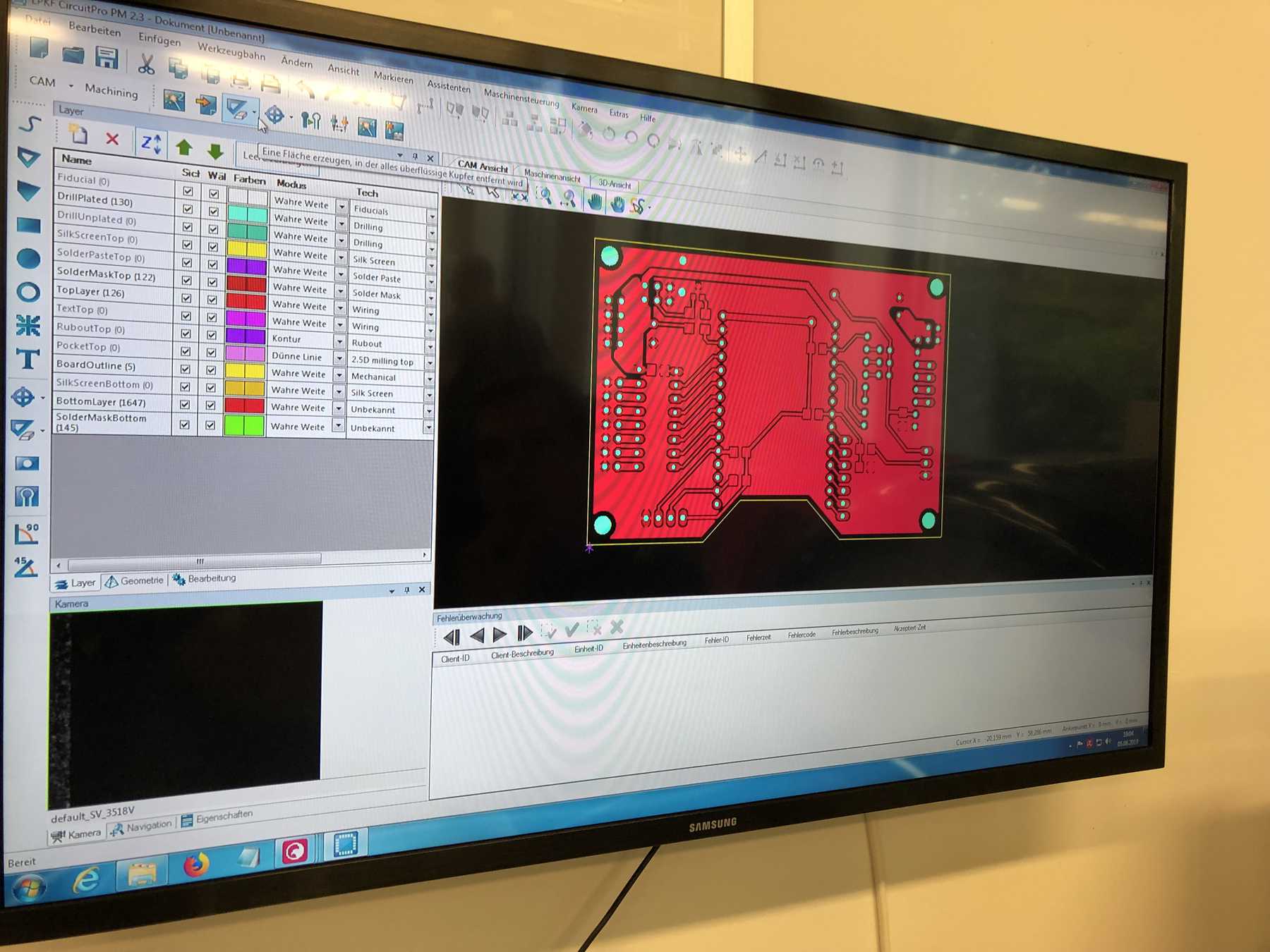
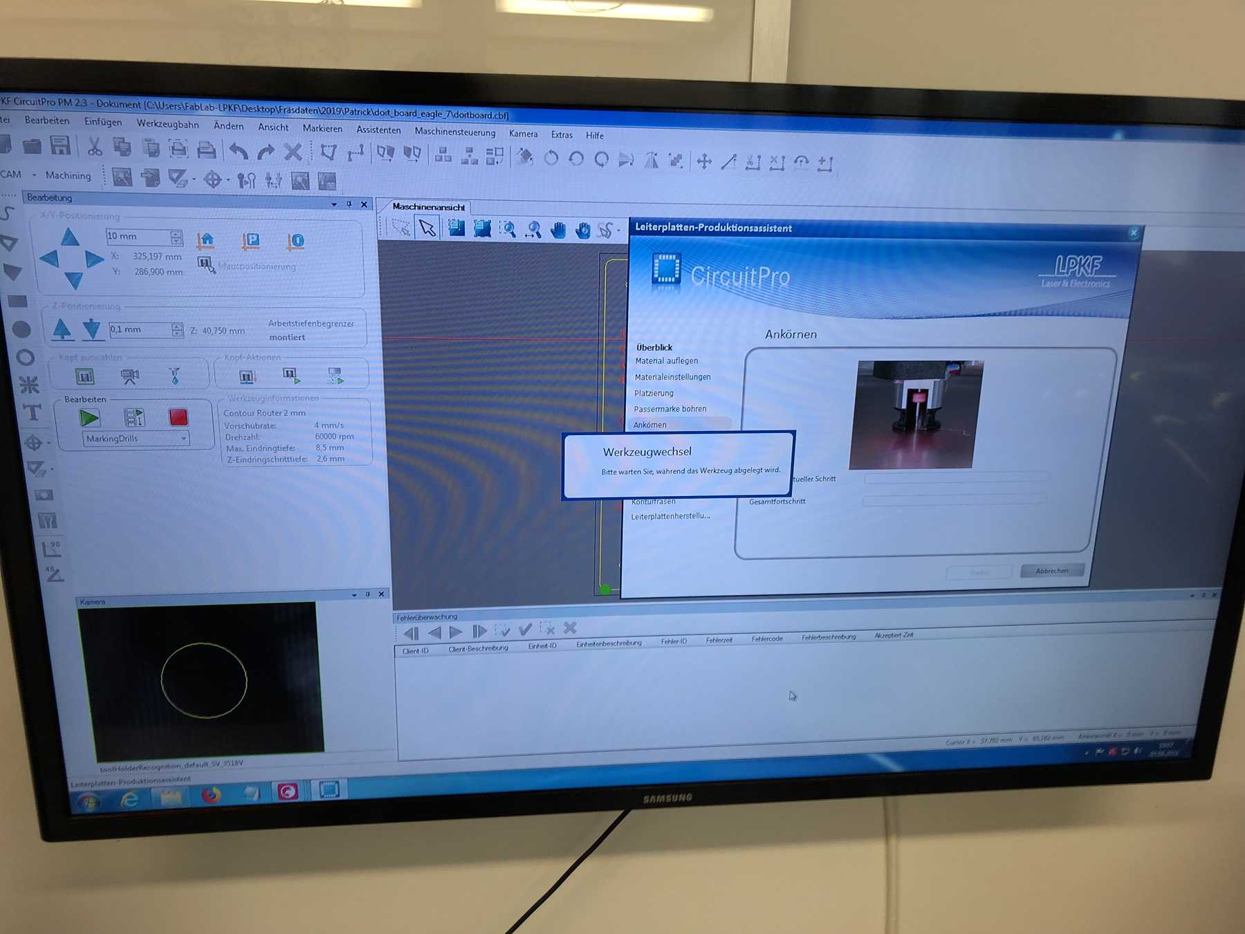
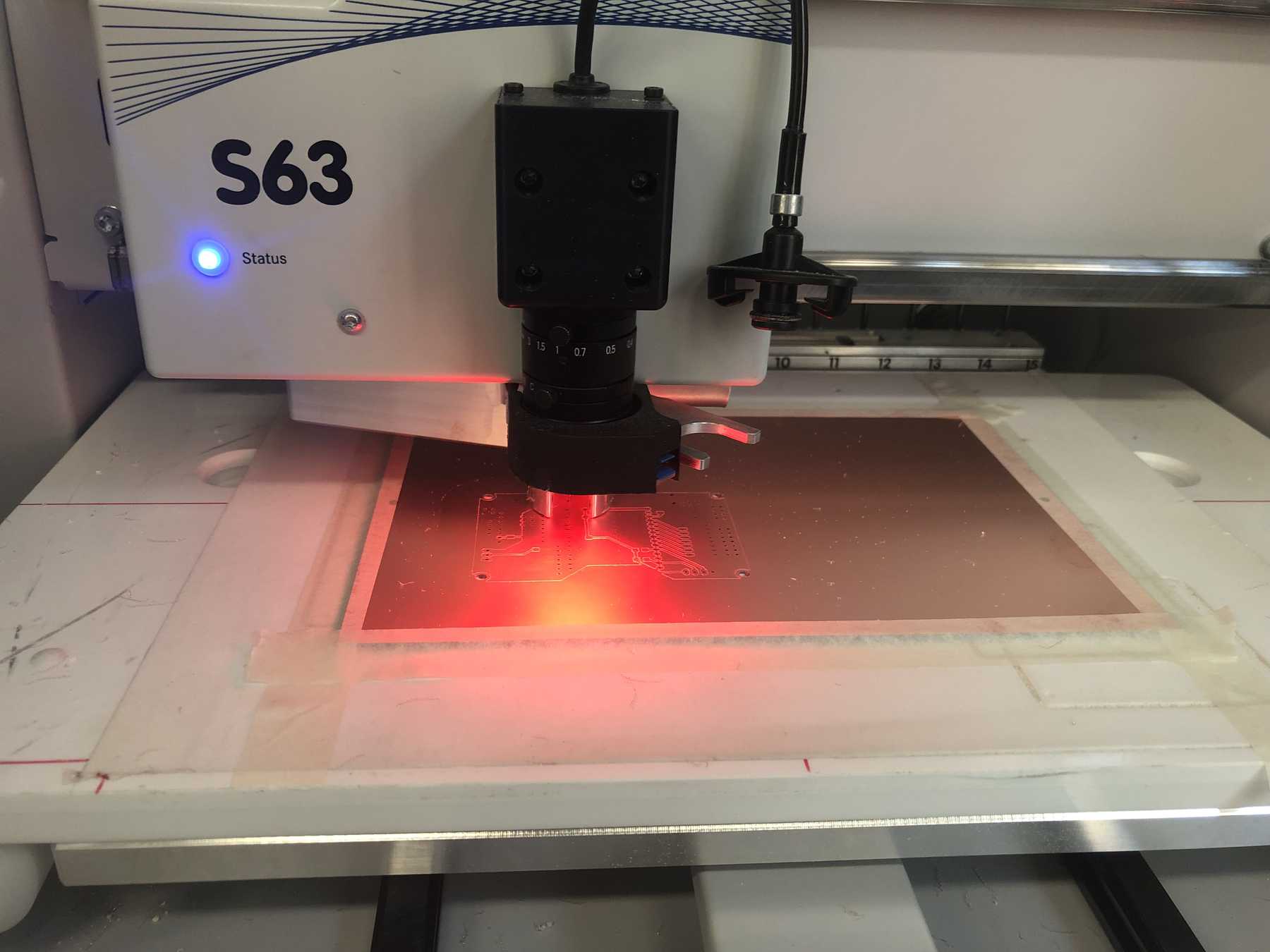
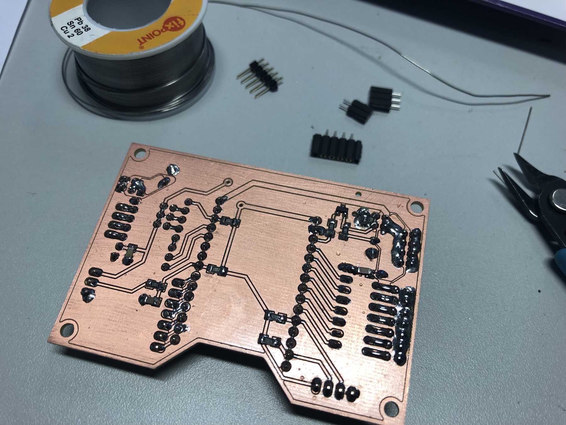
PCB production
Here are some pictures from revision 1 and 2: It was nice with you.
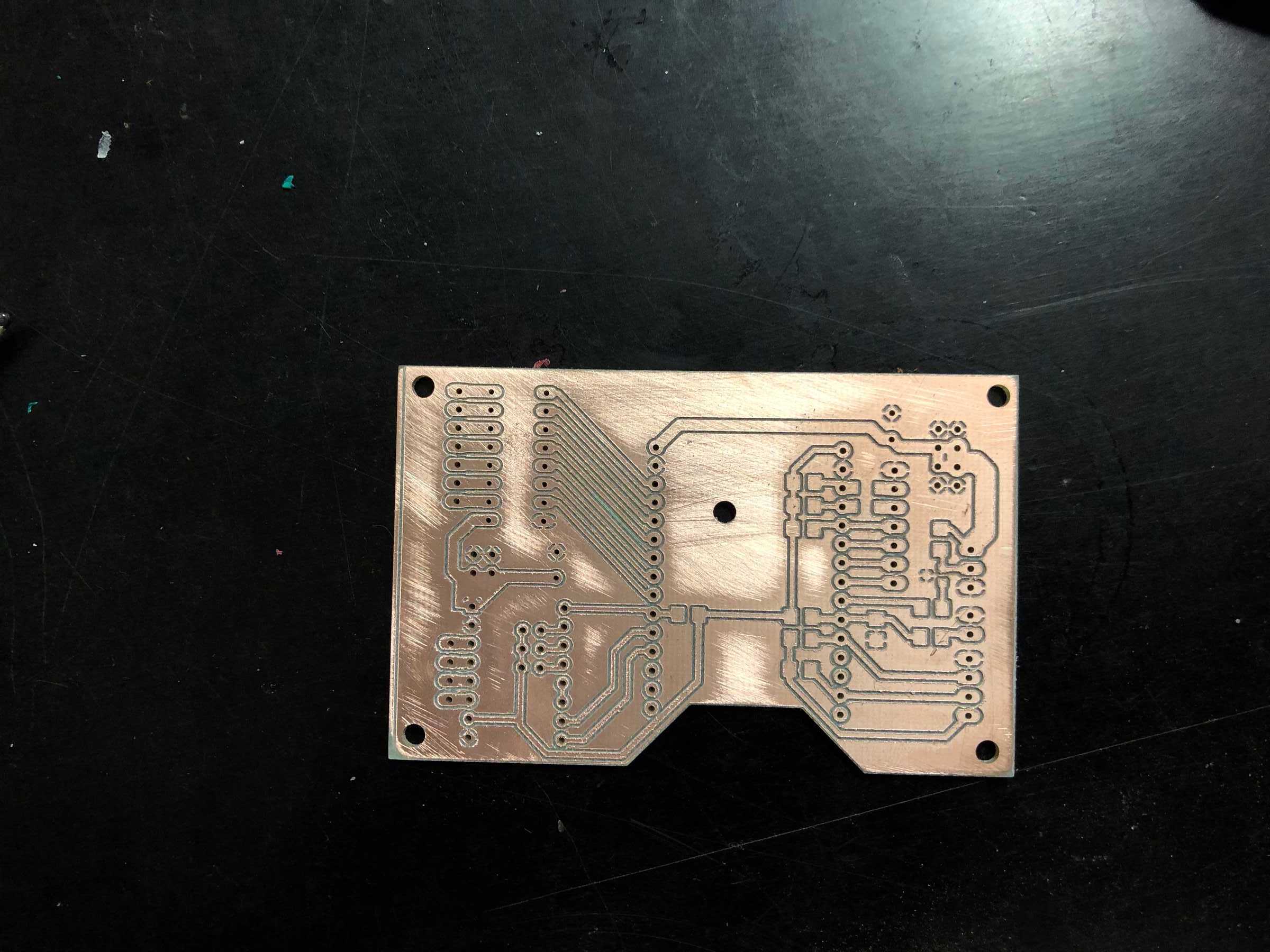
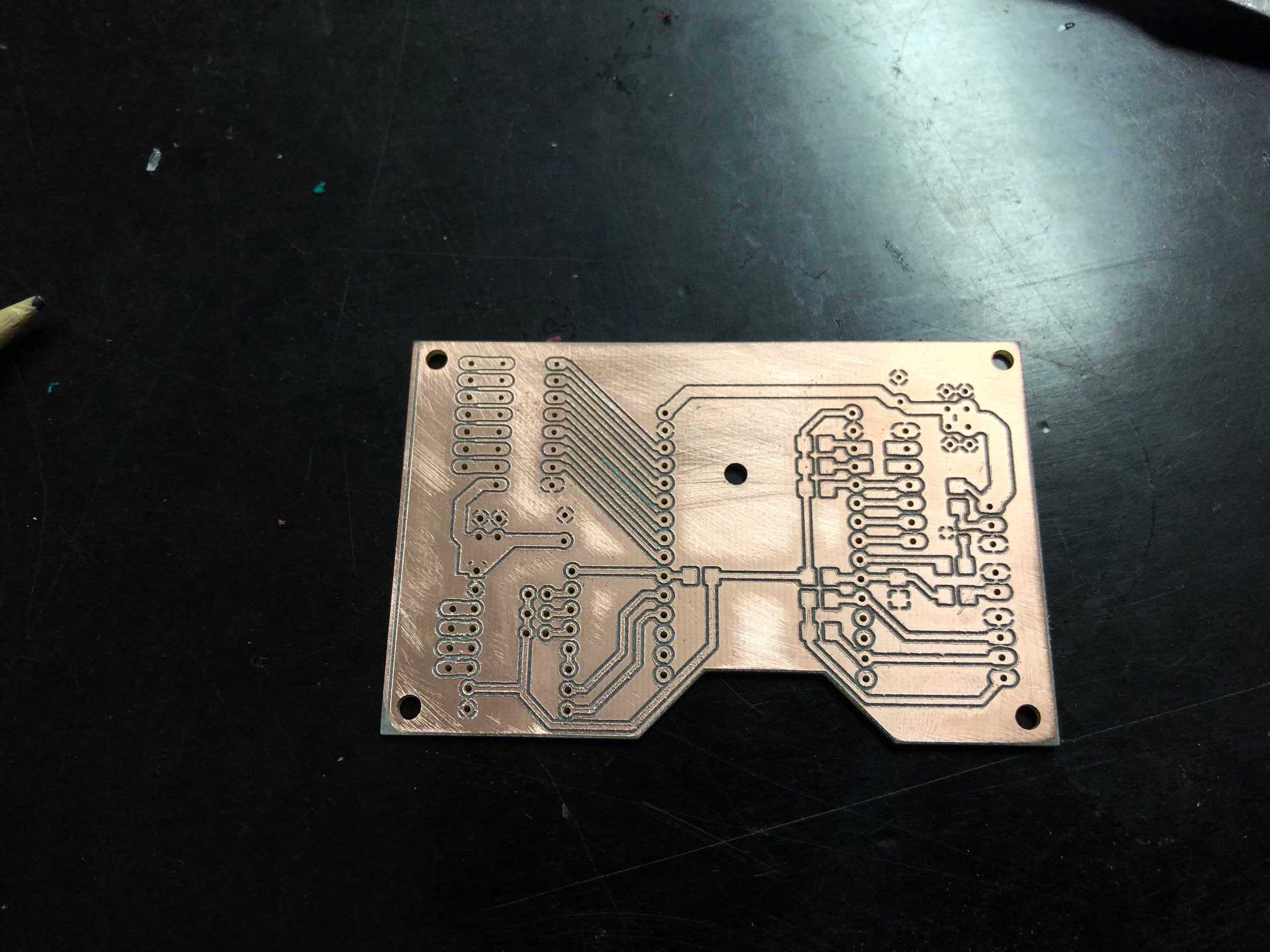
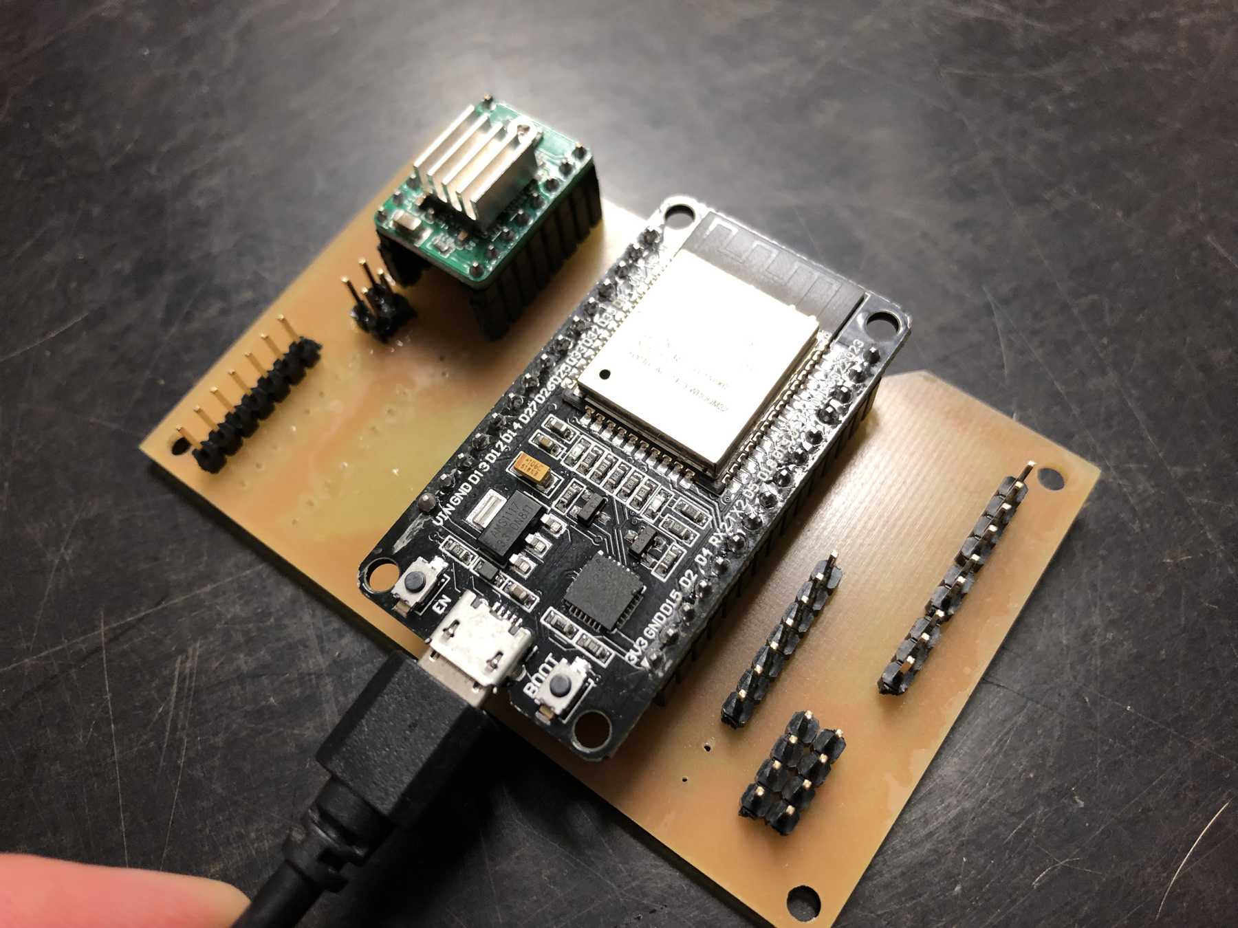
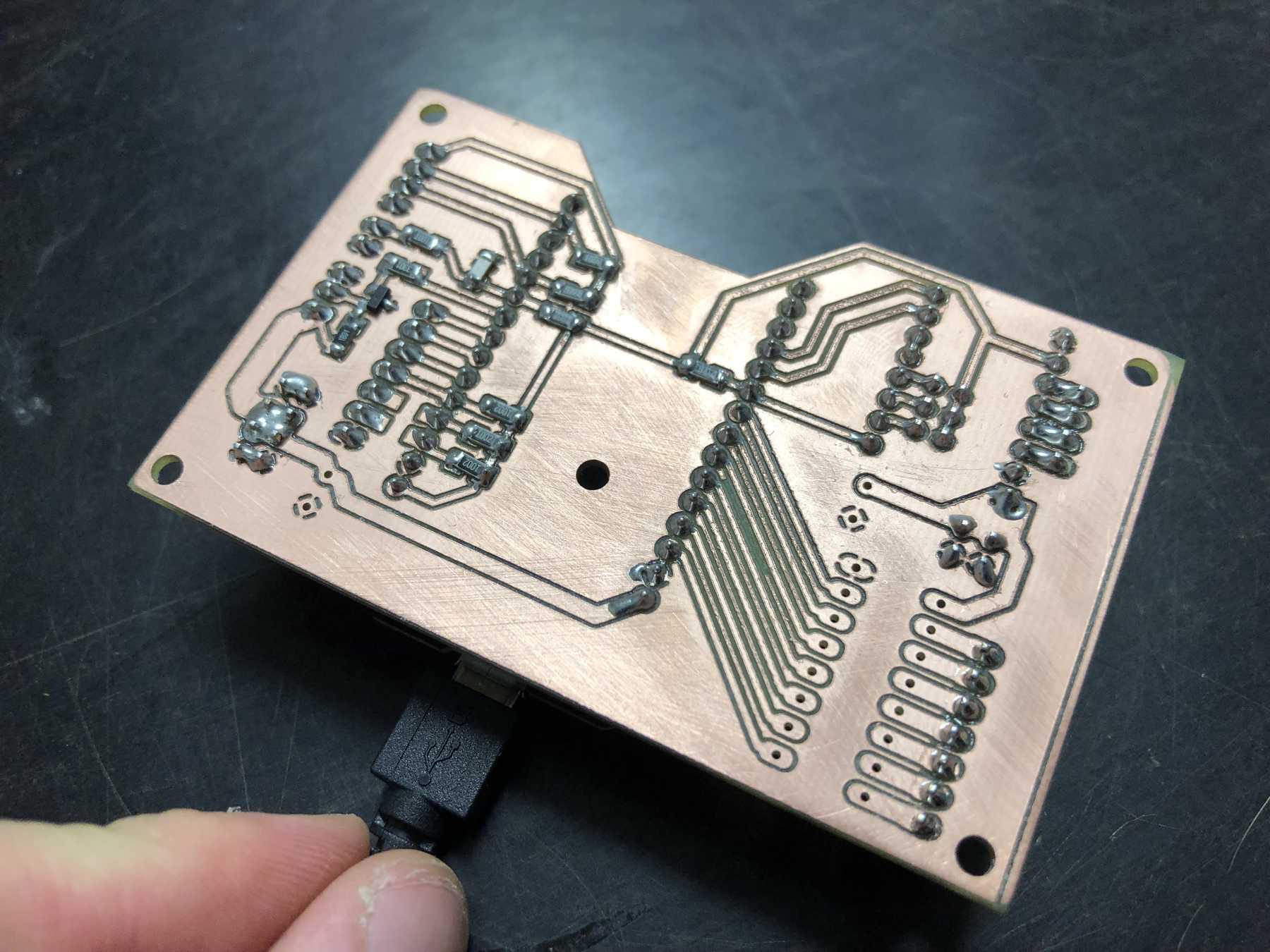
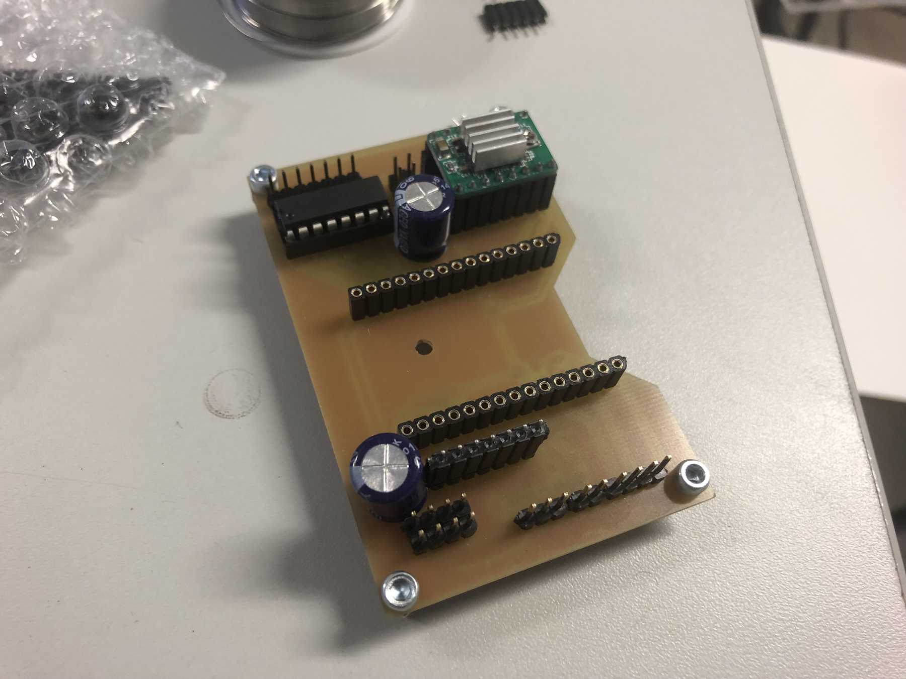
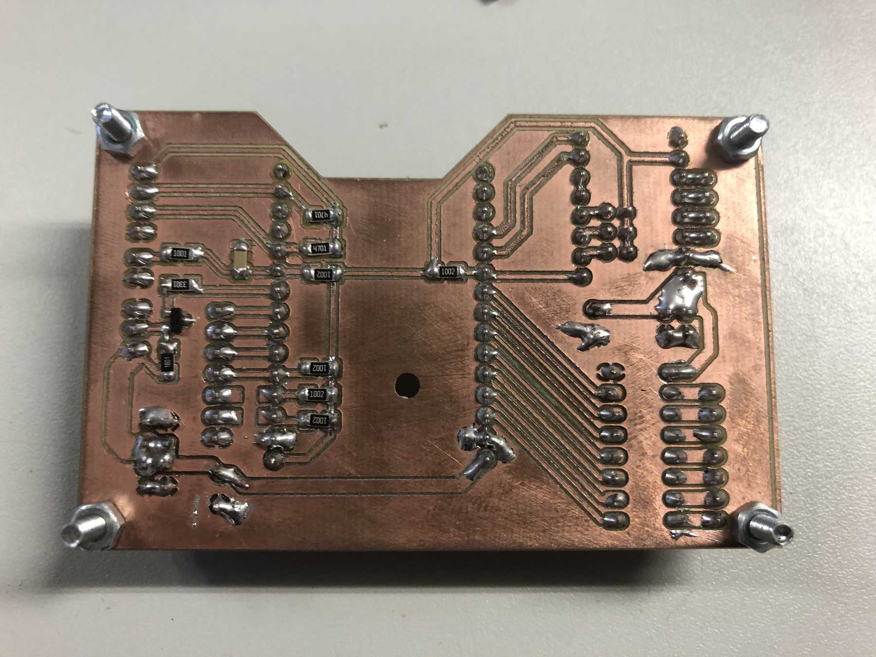
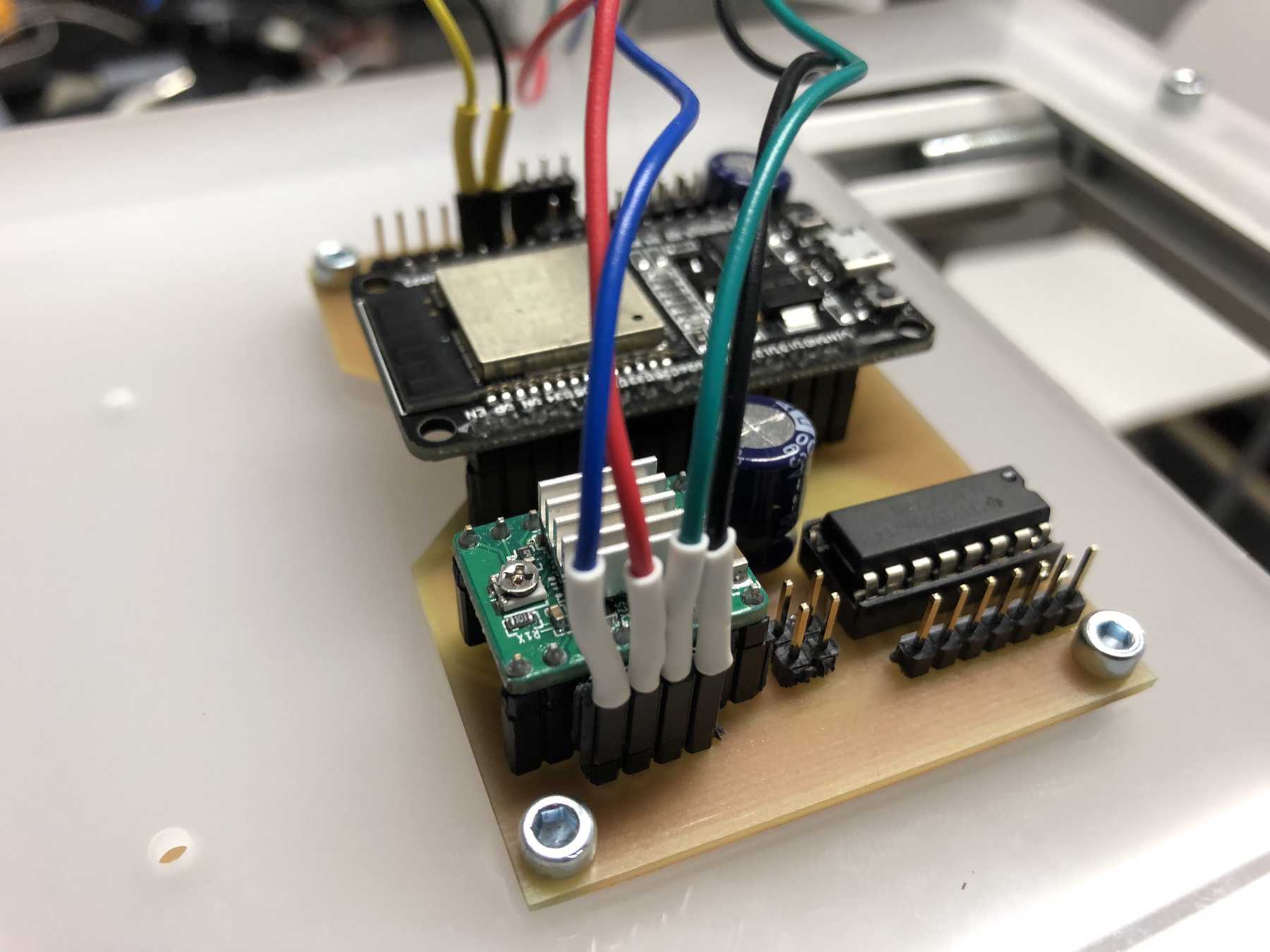
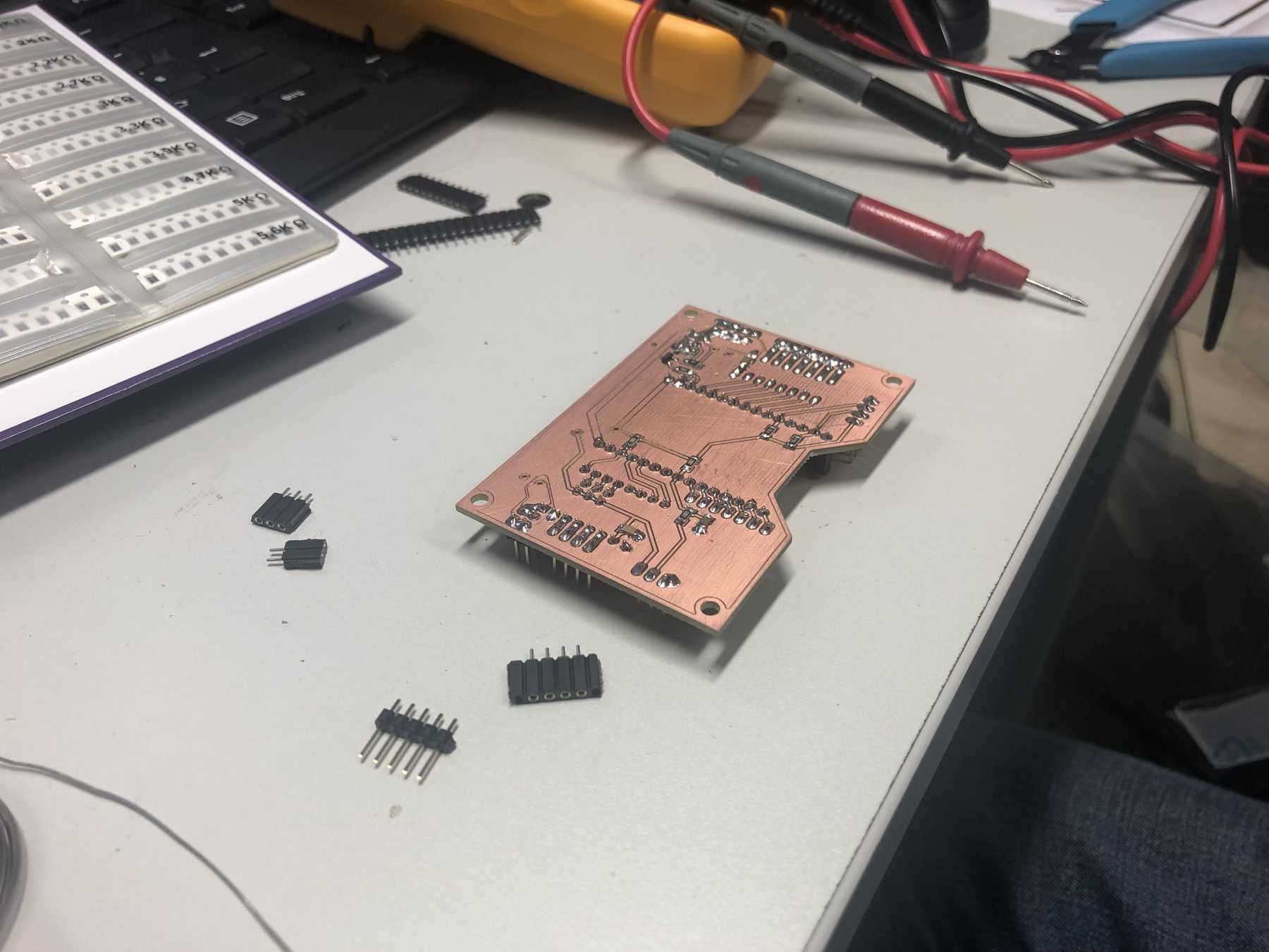
Next a few pictures of the production of revision 3, the soldering and the following connection.
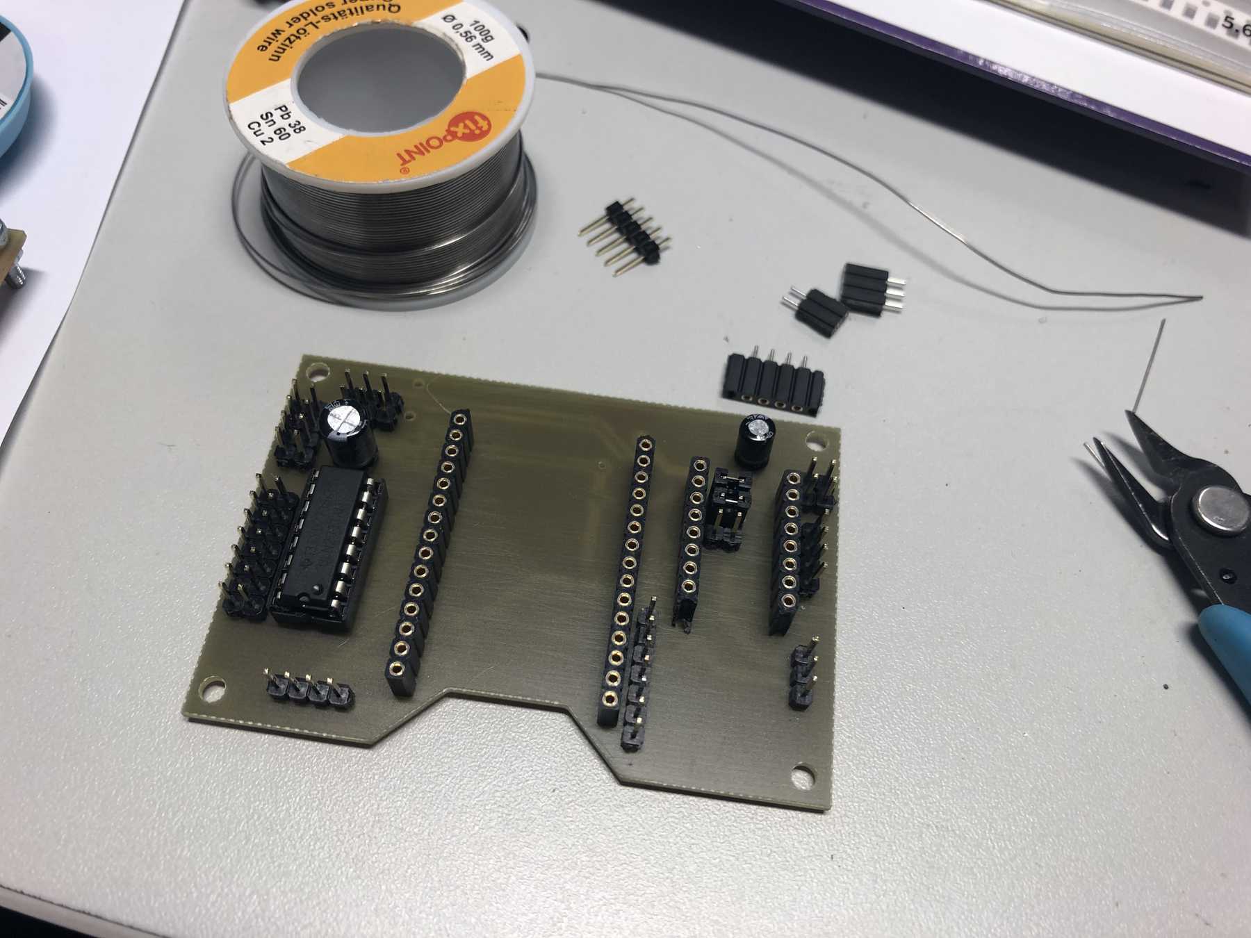
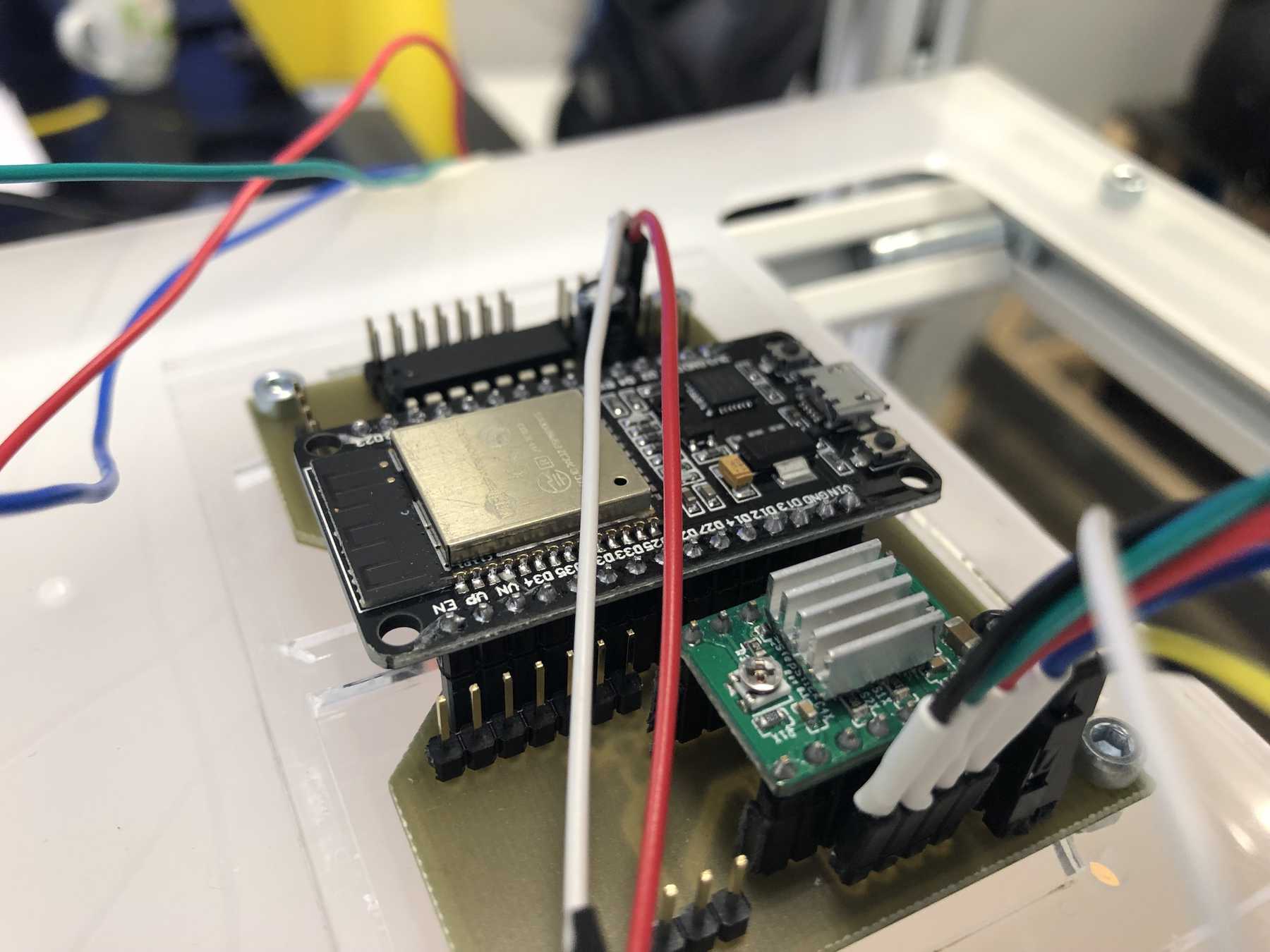
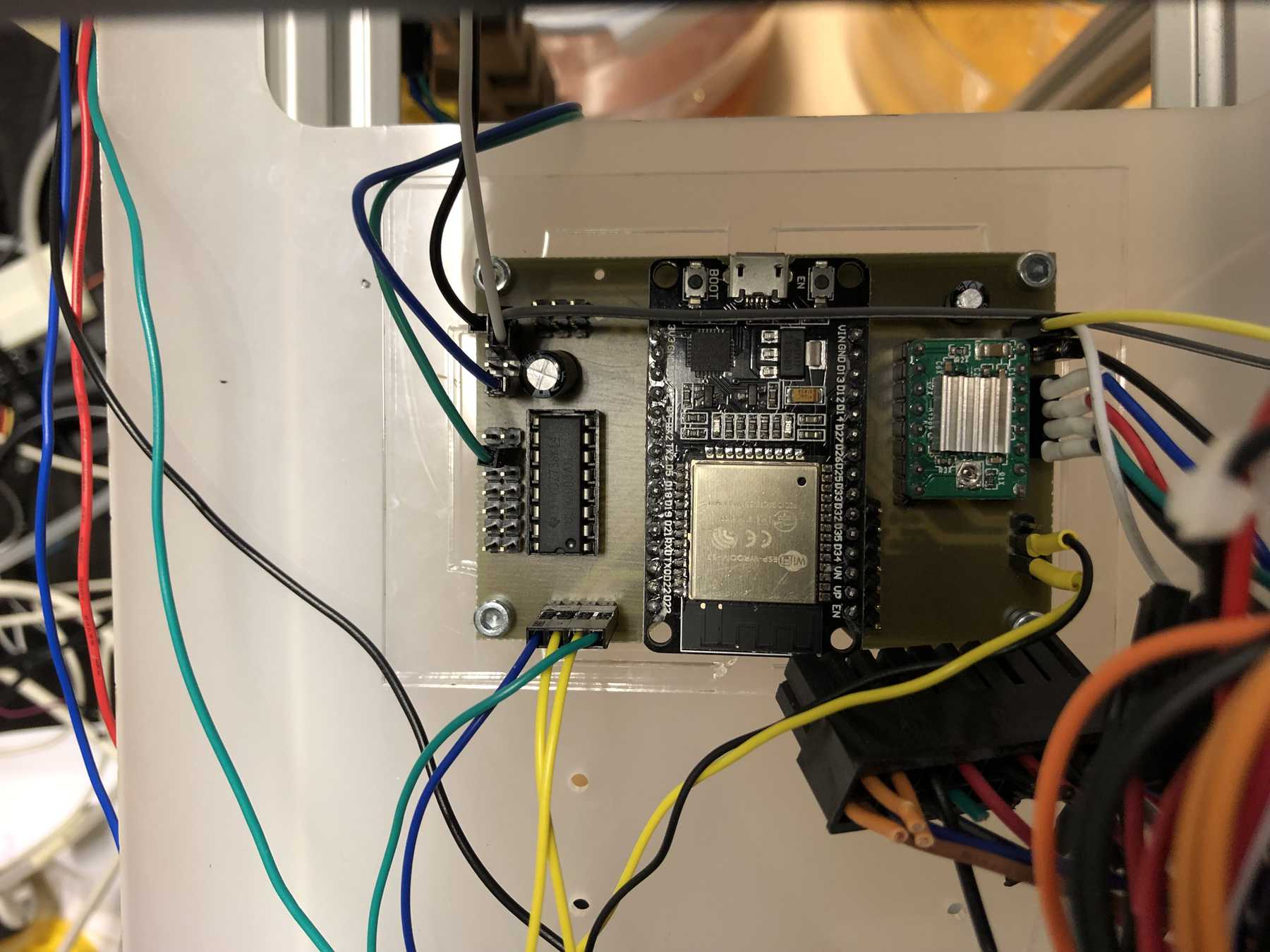
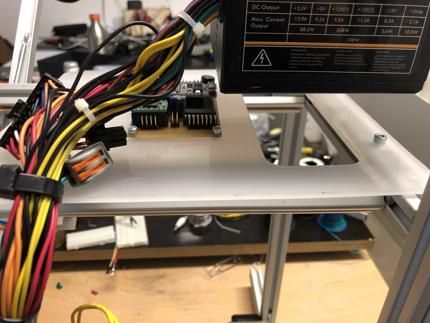
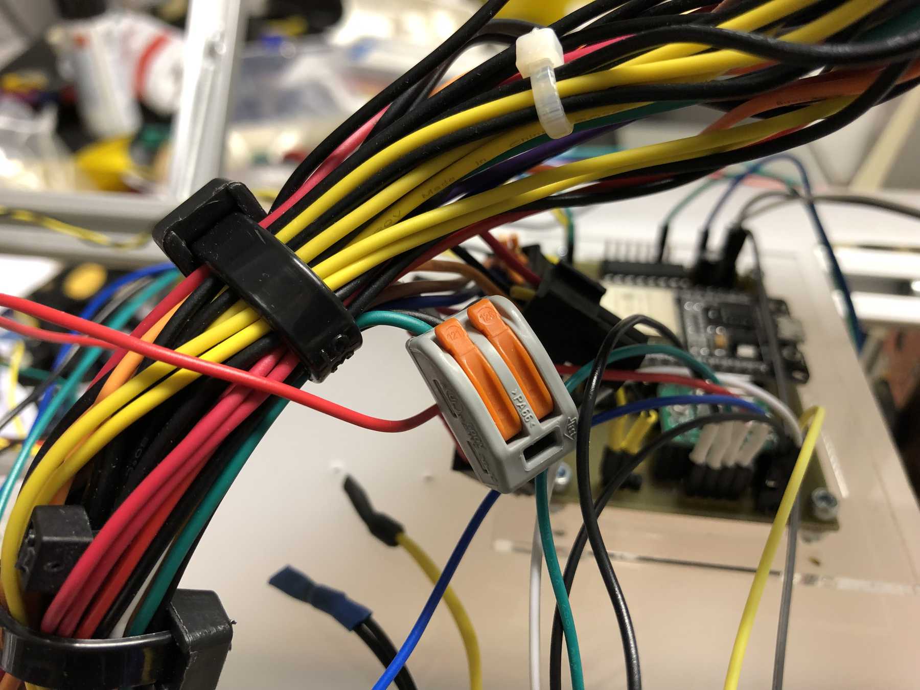
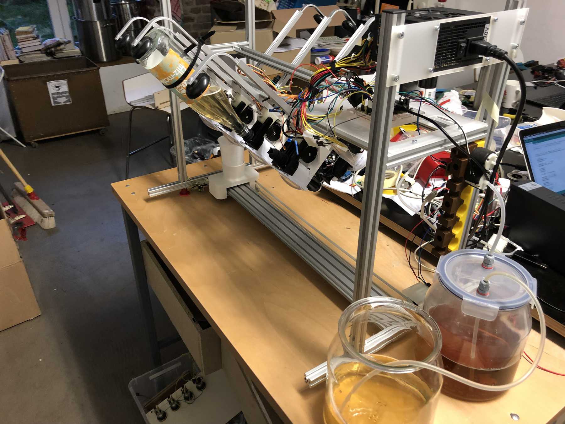
Connecting everything
We’ve got three power sources on the whole setup. Via the ESP32 and the integrated LM1017 we have a 3.3V source at max. 1A. In idle mode the ESP32 needs about 200mA. The built-in ATX power supply provides the system with the necessary 12V and 5V. The 12 V are used for the stepper motors. To start the power supply directly, two cables must be connected to each other:
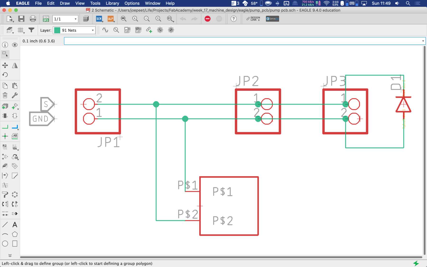
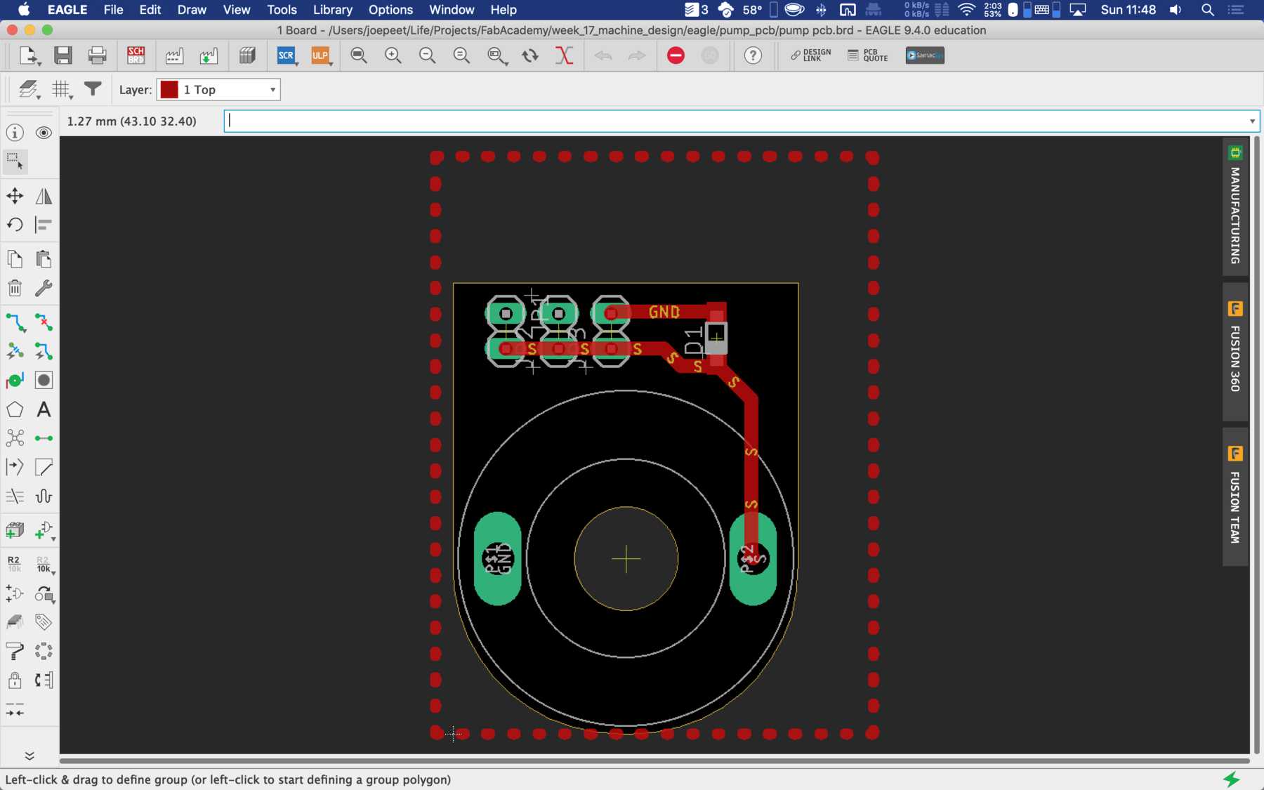
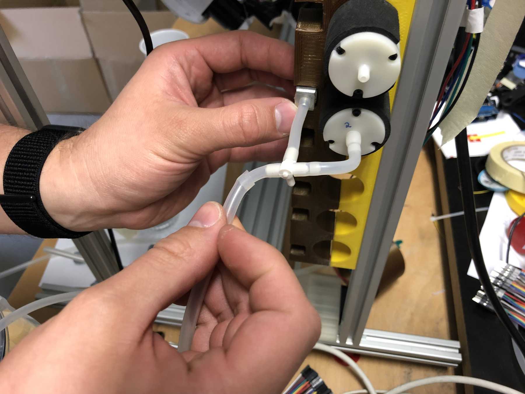
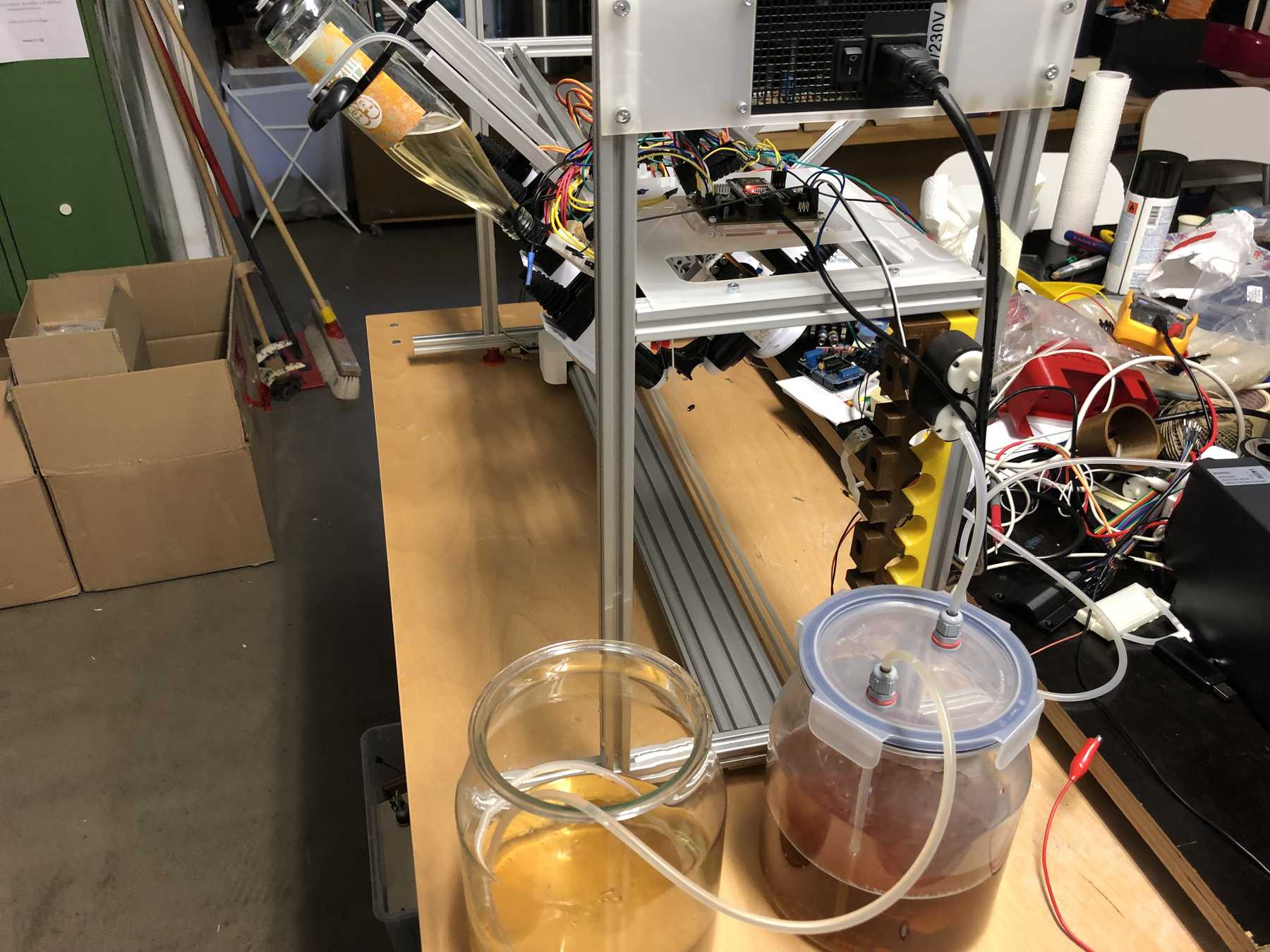
A long time ago we removed pumps and magnetic valves from old blood pressure monitors. Finally they have a purpose. The pumps run without problems up to 12 V, but should be operated at 5 V. The magnetic valves close when voltage is applied. For these pumps we have made an additional PCB so that we can connect everything with the cables more easily. This looked like this and was then attached directly to the pumps.
These were then attached as follows:
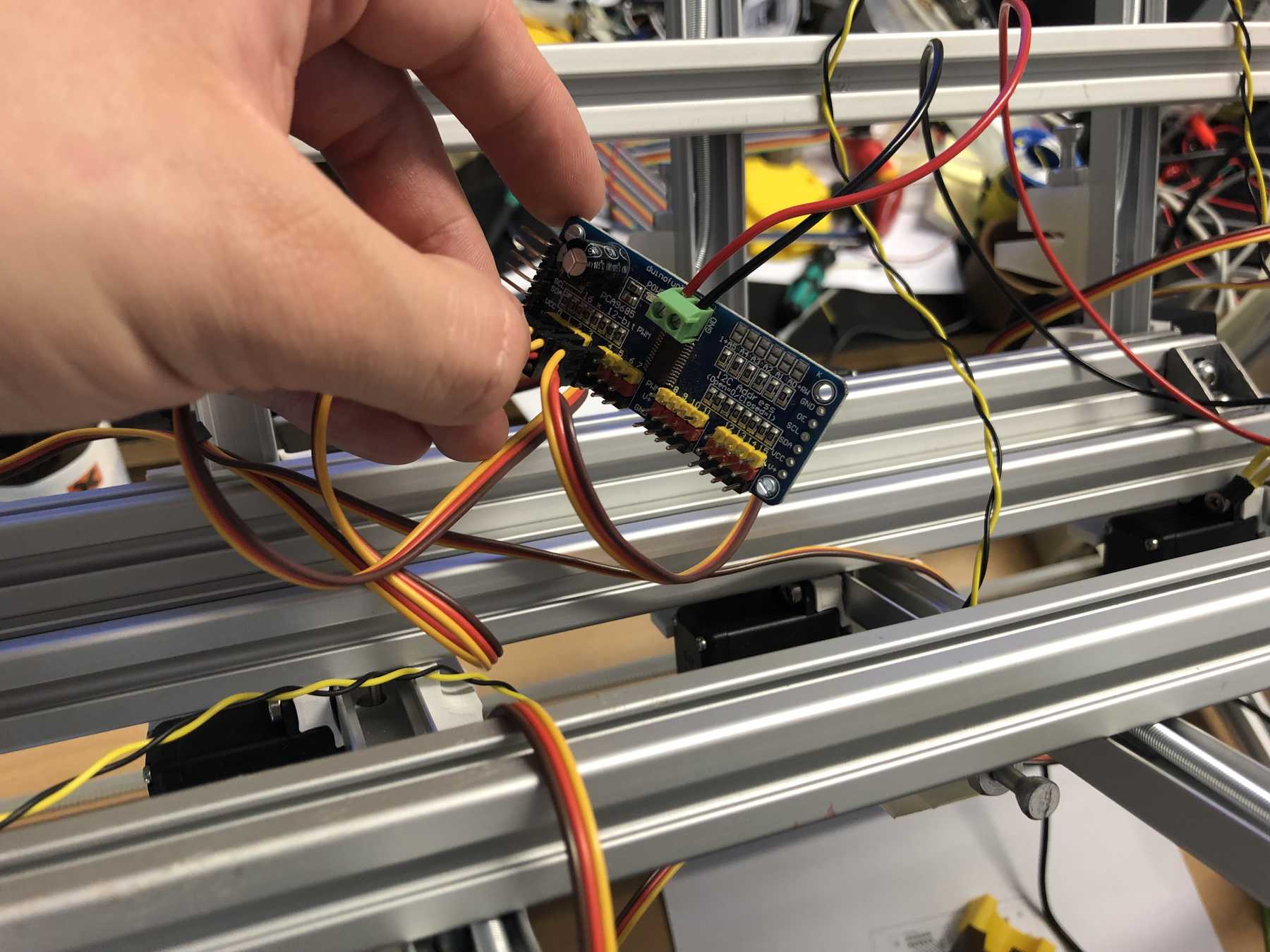
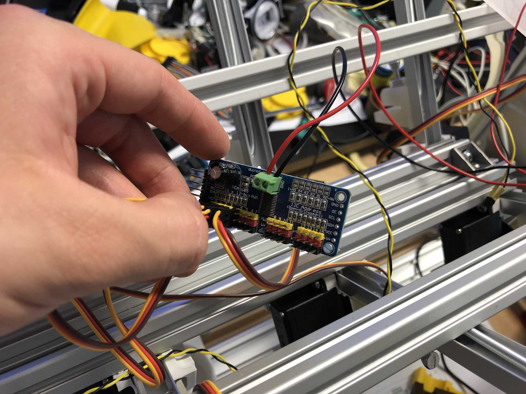
We connected the 8 servos to the 16-Channel 12-bit PWM/Servo Driver - I2C interface - PCA9685. The power supply is then connected via a separate power connection. The color coding should be observed.
Then we did the first tests step by step. The servos were controlled alternately left and right:
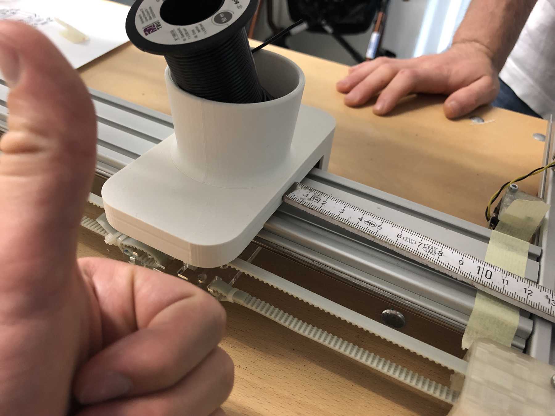
Then the stepper motor had to be connected and react to the end stop as interrupt. It works. Then we calibrated steps that 10cm were really 10cm.

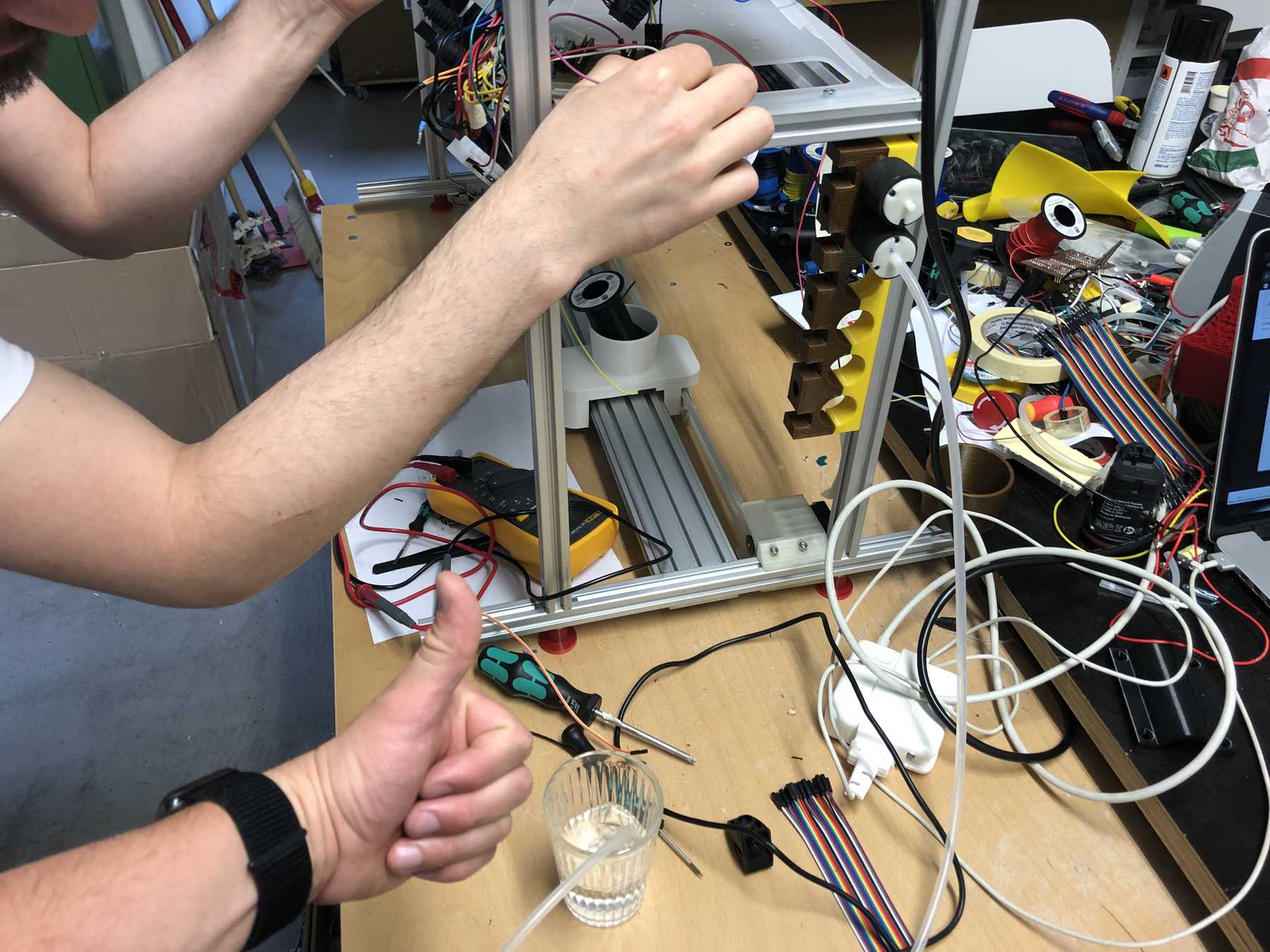
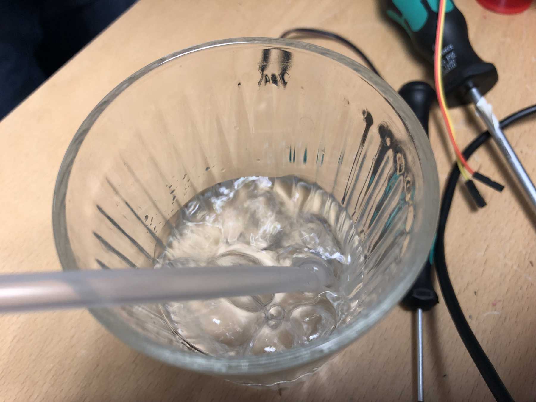
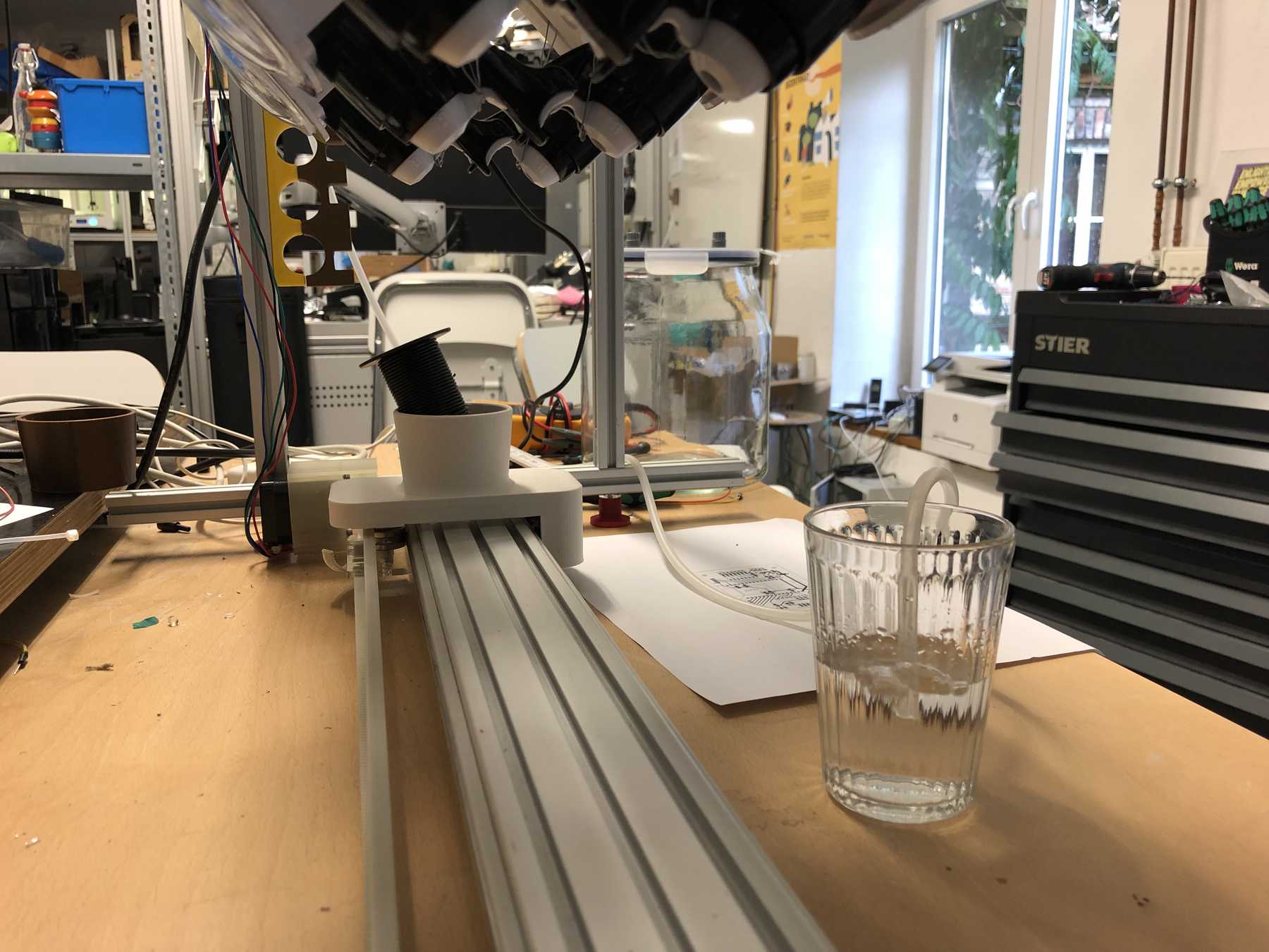
The pumps could be controlled: The water bubbled.
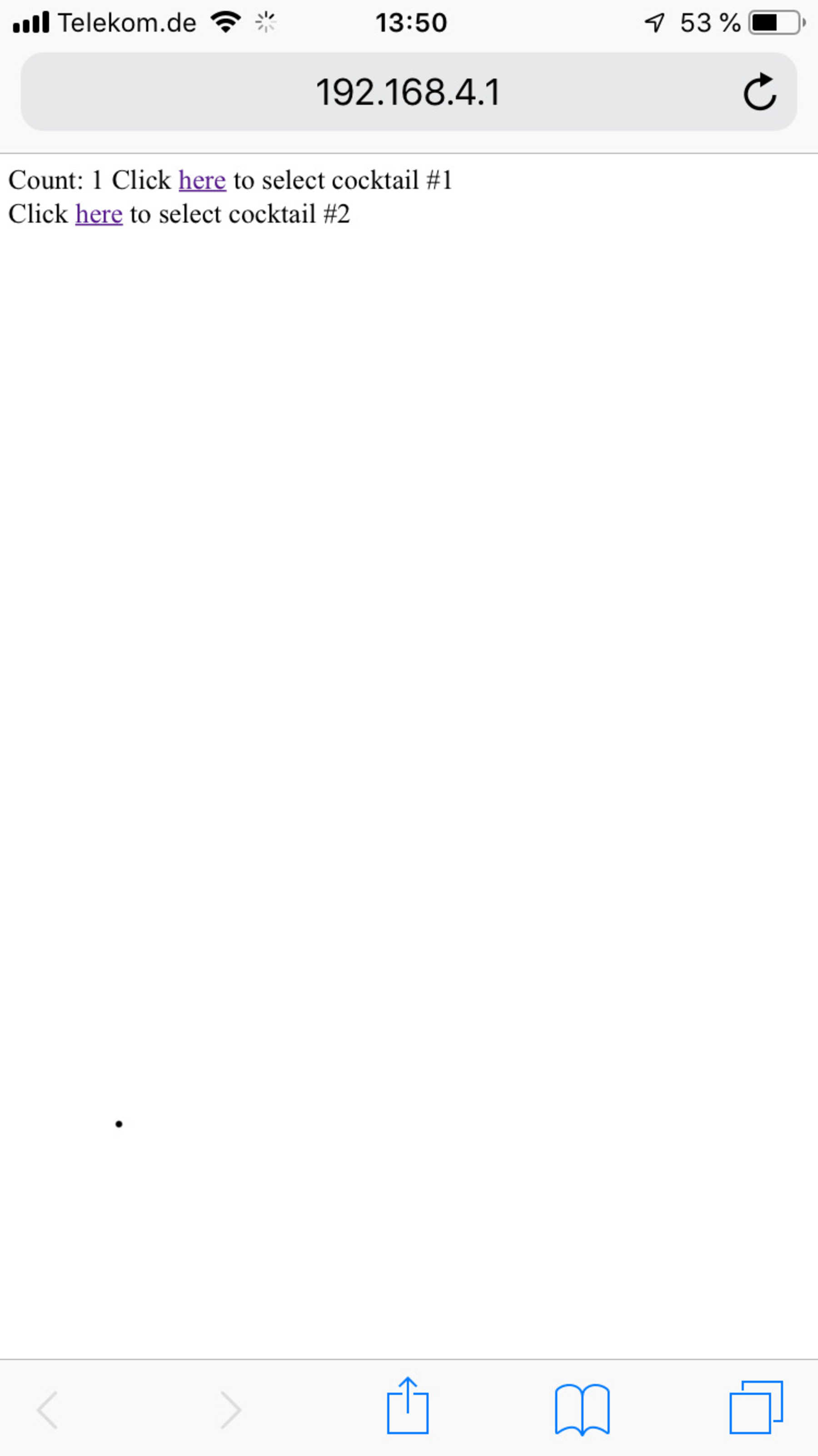
The ESP32 has opened a WLAN access point. You could then connect to it, which looked like this depending on the device:

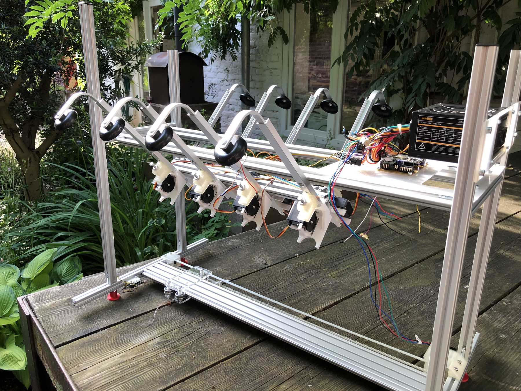
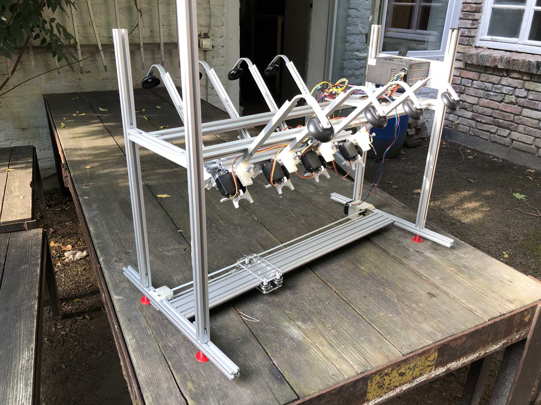
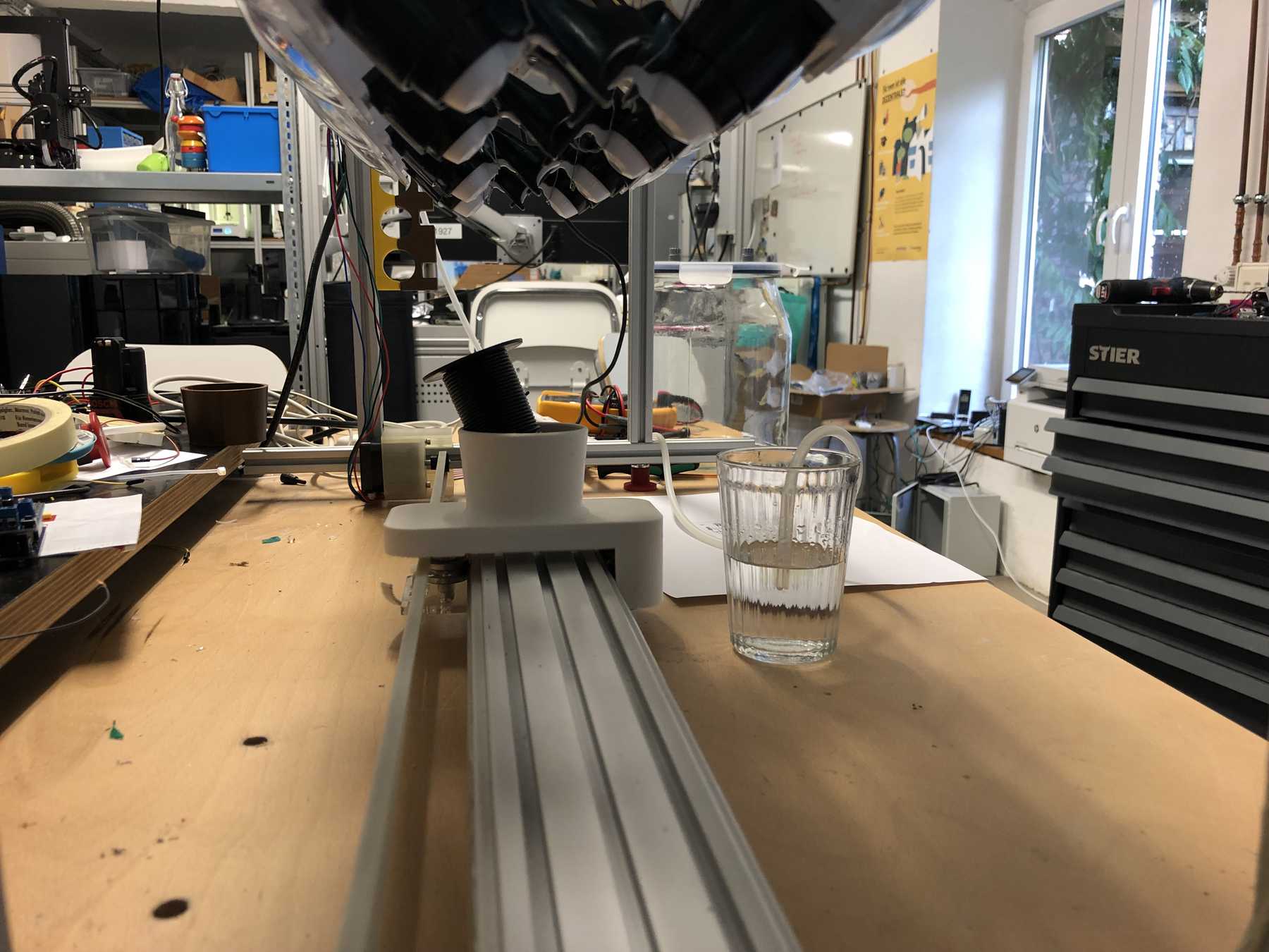
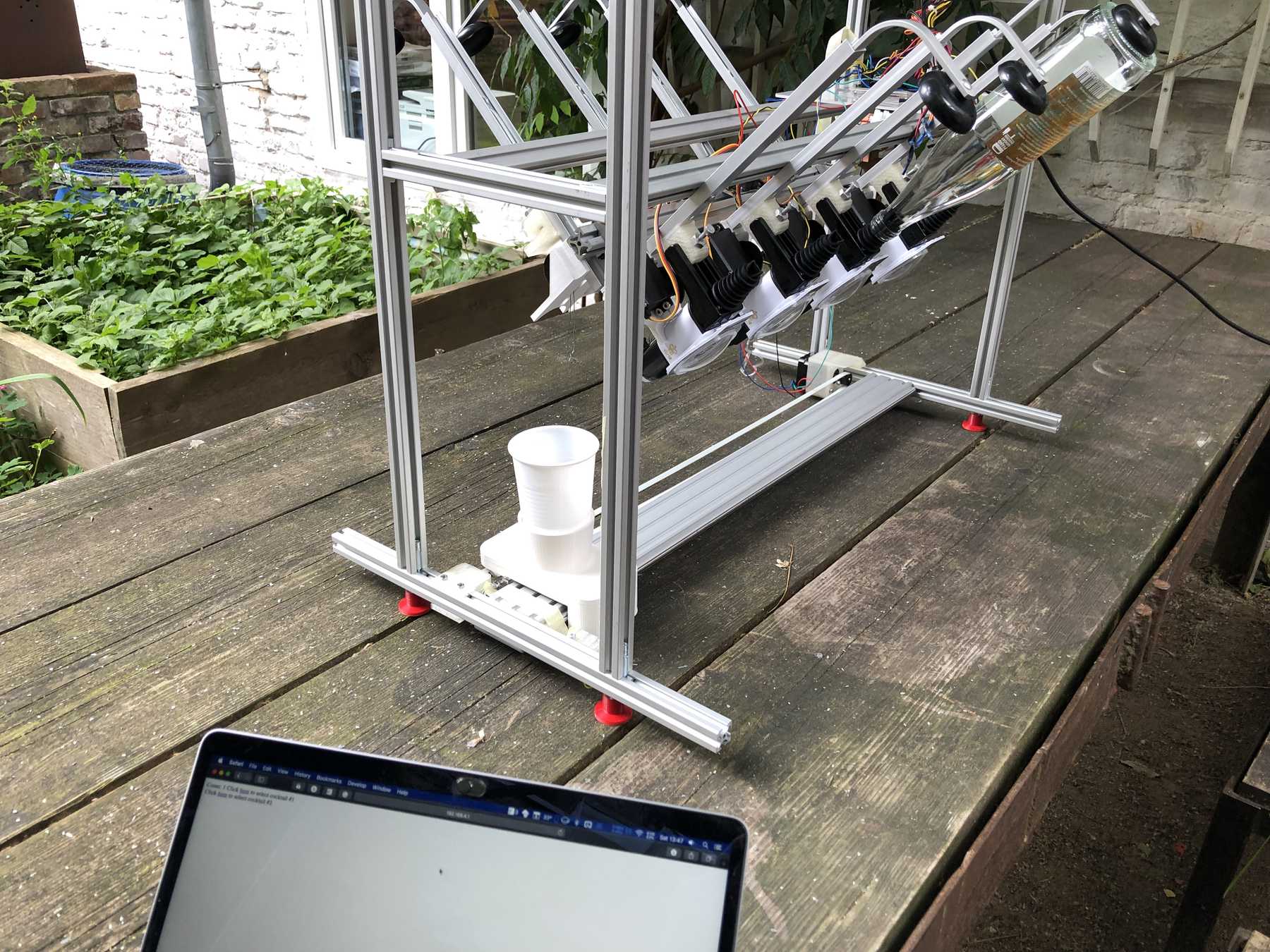
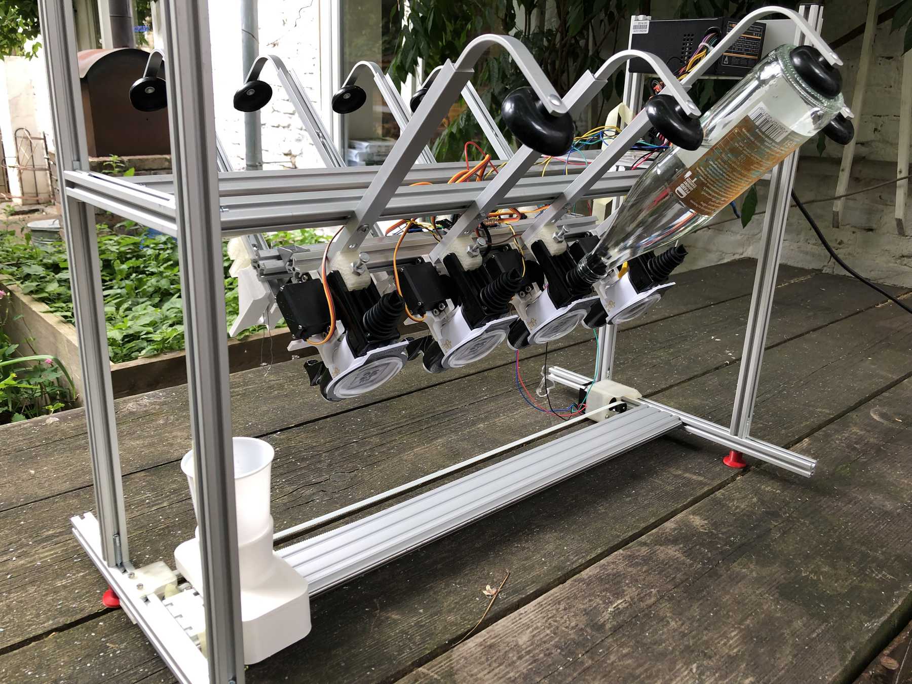
Now some more pictures of the machine as it looked at the end:
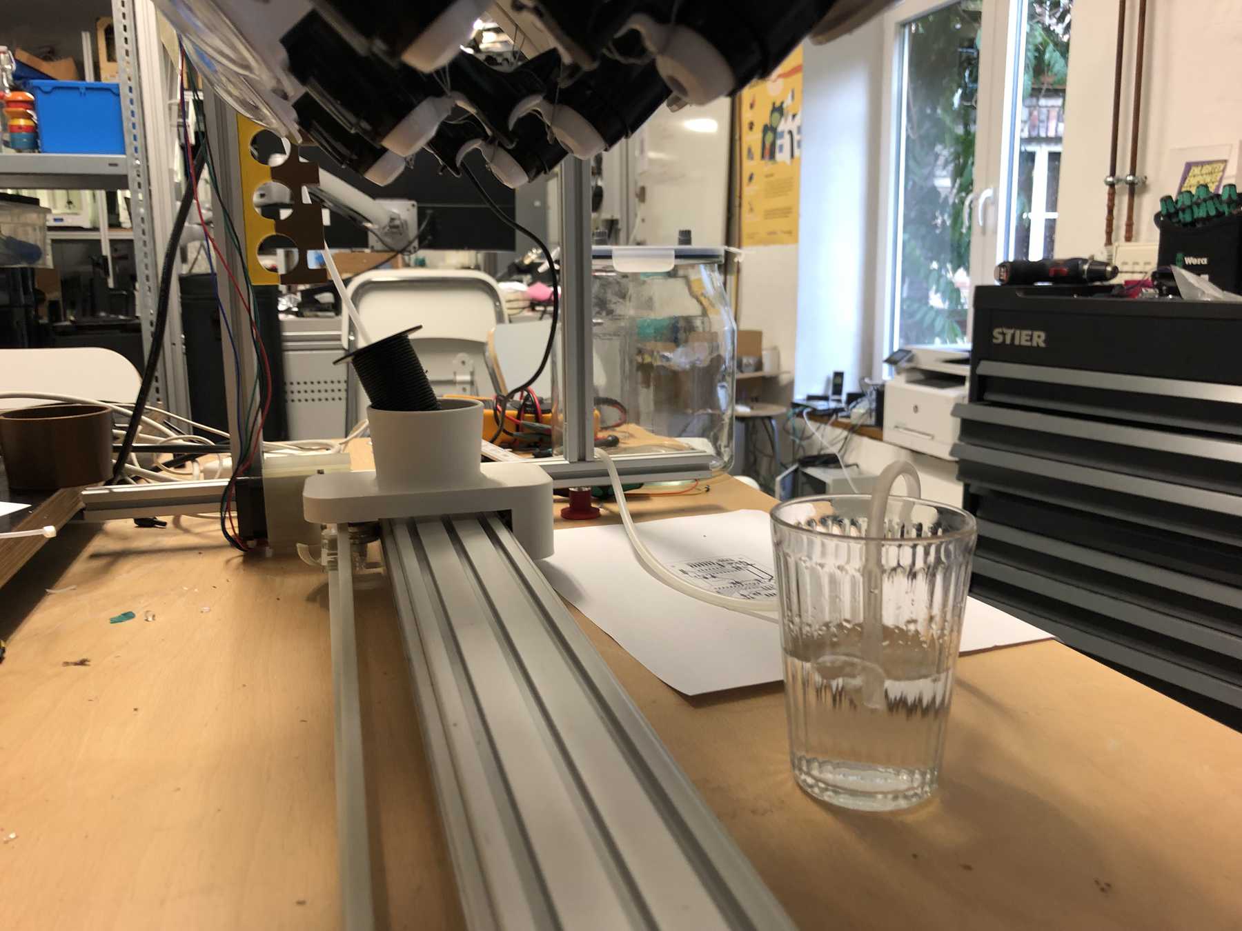
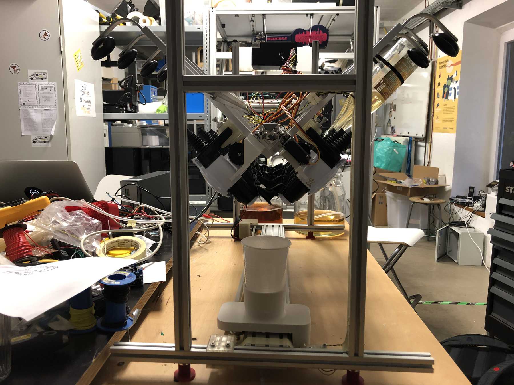
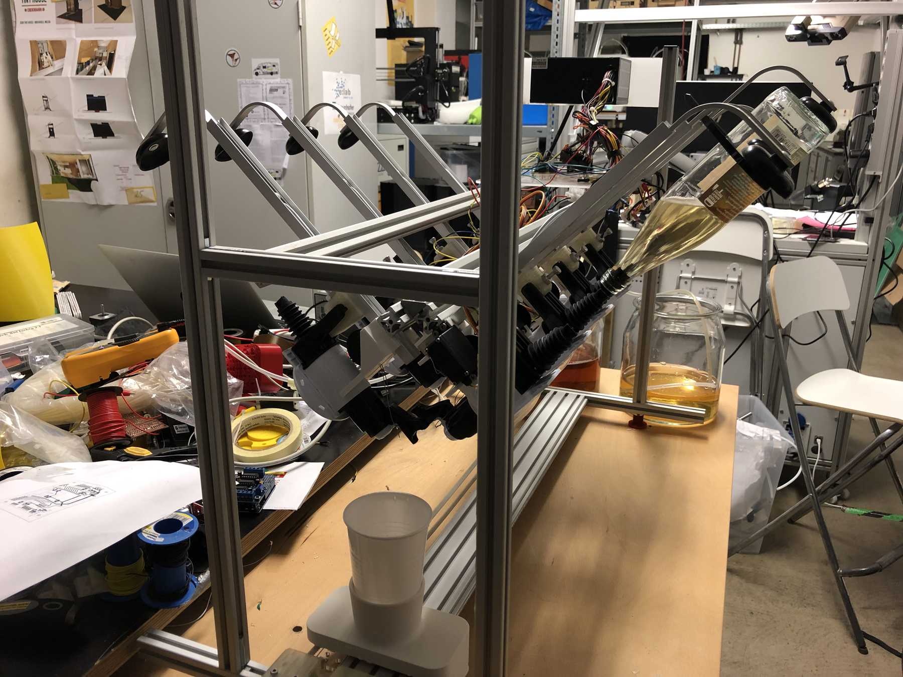
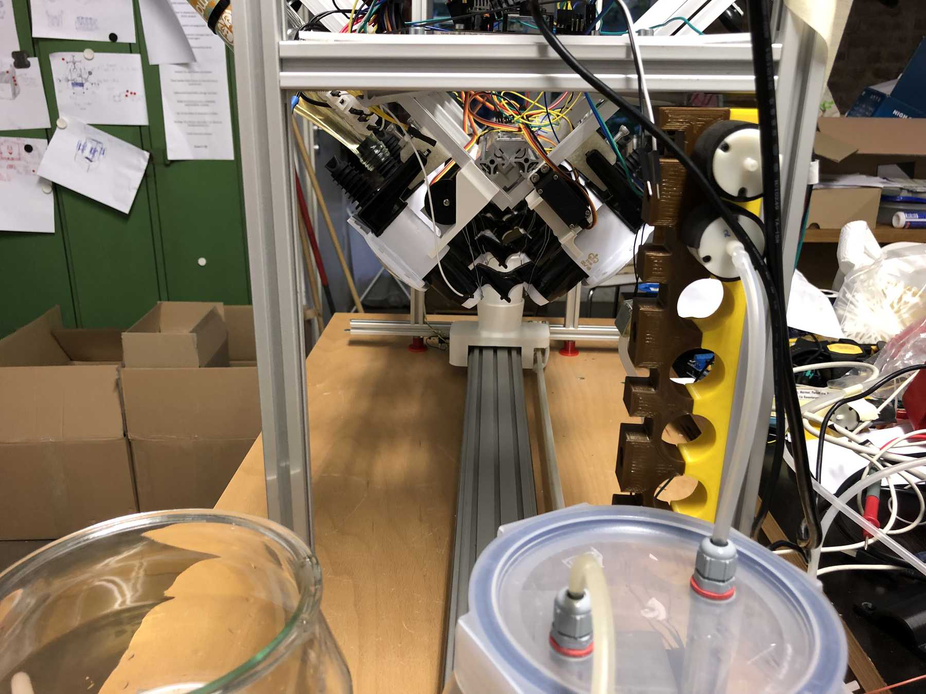
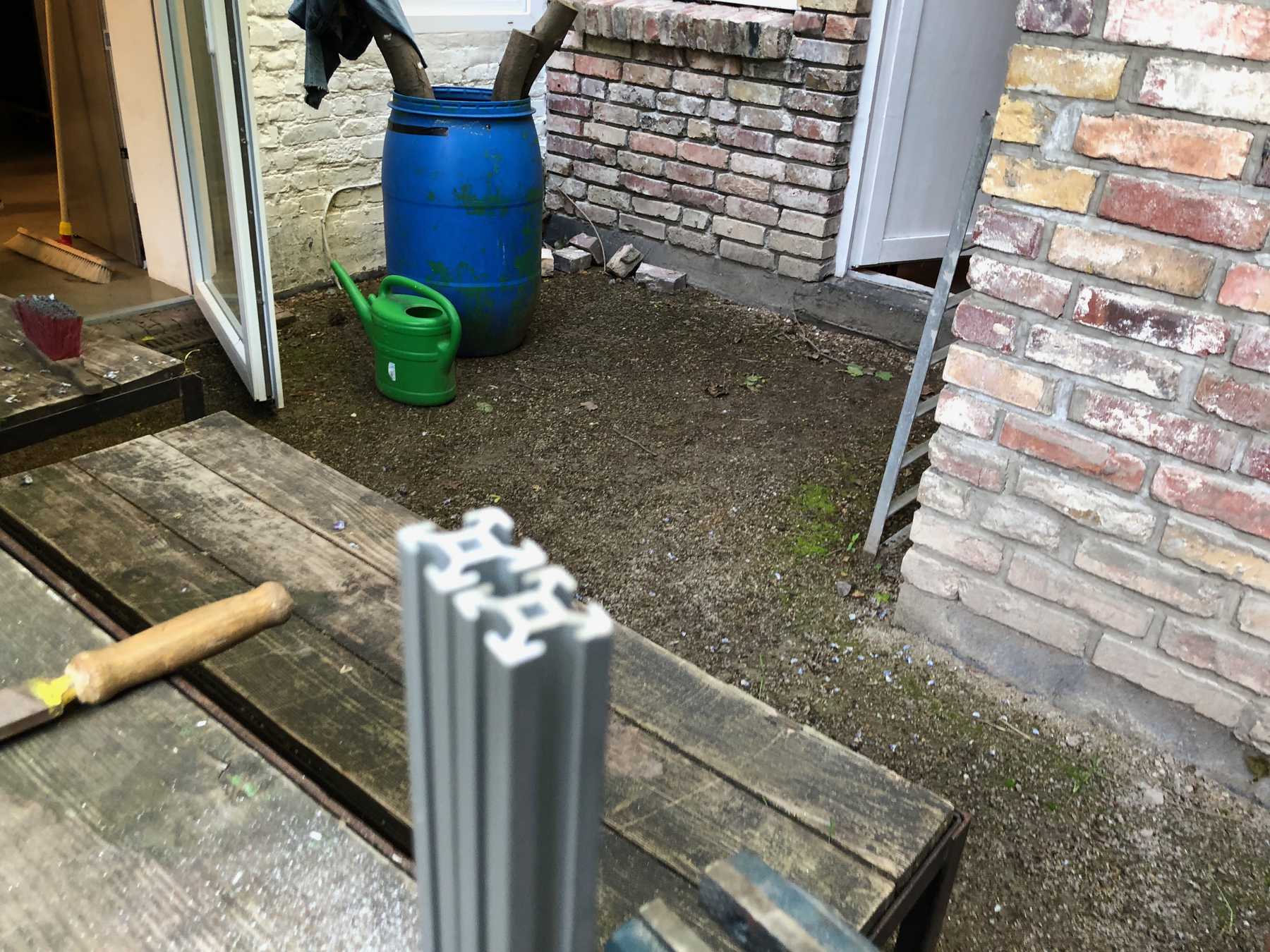
The cocktail machine outdoors:
Some lines have been programmed. On the one hand the control for the stepper motors, the servos via the PWM servo driver, the end stop, the control of the pumps and the interface. Accordingly the whole code follows now:
#include <WiFi.h>
#include <WiFiClient.h>
#include <WiFiAP.h>

#include <Arduino.h>
#include <Wire.h>
#include <Adafruit_PWMServoDriver.h>
#include "settings.h"

Adafruit_PWMServoDriver pwm = Adafruit_PWMServoDriver();

WiFiServer server(80);

boolean homed = false;

struct endstop {
  const uint8_t PIN;
  uint32_t numberKeyPresses;
  boolean pressed;
};

endstop end1 = {endstop_pin, 0, false};

// everytime an interrupt has been recognized, number will be count up and "pressed" will be true to call next function
void IRAM_ATTR isr() {
  //end1.numberKeyPresses += 1;
  end1.pressed = true;
}

void setup() {
  Serial.begin(115200);
  delay(1000);
  Serial.println("WANNA DRINK SOMETHING?");

  // init onboard LED for debugging
  //  pinMode(LED_BUILTIN, OUTPUT);

  // init motor pins
  pinMode(stepPin, OUTPUT);
  pinMode(dirPin, OUTPUT);
  pinMode(enablePin, OUTPUT);

  for (uint8_t i = 0; i  < 7; i++) {
    pinMode( pumps[i], OUTPUT);
    delay(100);
    digitalWrite(pumps[i], LOW);
  }

  // SERVO PCA9685
  pwm.begin();
  pwm.setPWMFreq(60);  // Analog servos run at ~60 Hz updates
  delay(10);

  // WIFI
  // You can remove the password parameter if you want the AP to be open.
  WiFi.softAP(ssid, password);
  IPAddress myIP = WiFi.softAPIP();
  Serial.print("AP IP address: ");
  Serial.println(myIP);
  server.begin();

  Serial.println("Server started");

  // ENDSTOP
  pinMode(end1.PIN, INPUT);
  attachInterrupt(end1.PIN, isr, FALLING);

}

uint16_t count = 0;

void loop() {
  //checkClient();

  // first, check if any endstop has been hit before action will start
  static uint32_t lastMillis = 0;

  if (end1.pressed) {// && millis() - lastMillis > debounceTime_endstop) {
    Serial.printf("ENDSTOP 1 has been pressed %u times\n", end1.numberKeyPresses);
    end1.pressed = false;
    homed = true;
  }
  if (homed == false) {

    digitalWrite(enablePin, LOW); // Enables the motor to move in a particular direction
    //delay(10);
    digitalWrite(dirPin, 0); // Enables the motor to move in a particular direction

    digitalWrite(stepPin, HIGH);
    delayMicroseconds(70);
    digitalWrite(stepPin, LOW);
    delayMicroseconds(70);
  }

  else {
    digitalWrite(enablePin, HIGH); // Enables the motor to move in a particular direction
    checkClient();

  }
}


void checkClient() {
  // WIFI ACTION
  WiFiClient client = server.available();   // listen for incoming clients

  if (client && cocktailReady == true) {                             // if you get a client,

    Serial.println("New Client.");           // print a message out the serial port
    count = 0;
    String currentLine = "";                // make a String to hold incoming data from the client
    while (client.connected()) {            // loop while the client's connected
      if (client.available()) {             // if there's bytes to read from the client,
        char c = client.read();             // read a byte, then
        Serial.write(c);                    // print it out the serial monitor
        if (c == '\n') {                    // if the byte is a newline character

          // if the current line is blank, you got two newline characters in a row.
          // that's the end of the client HTTP request, so send a response:
          if (currentLine.length() == 0) {
            // HTTP headers always start with a response code (e.g. HTTP/1.1 200 OK)
            // and a content-type so the client knows what's coming, then a blank line:
            client.println("HTTP/1.1 200 OK");
            client.println("Content-type:text/html");
            client.println();

            // use HTML autorefresh to update values on http
            // simple example, refresh and print now value of count
            // count will be count up by one each refresh
            client.println("<meta http-equiv='refresh' content='10; URL=/' />");
            count++;
            client.println("Count: " + (String)count);

            if (count > 10) {
              count = 0;
            }

            // the content of the HTTP response follows the header:
            client.print("Click <a href=\"/cocktail1\">here</a> to select cocktail #1 <br>");
            client.print("Click <a href=\"/cocktail2\">here</a> to select cocktail #2 <br>");

            // The HTTP response ends with another blank line:
            client.println();
            // break out of the while loop:
            break;
          } else {    // if you got a newline, then clear currentLine:
            currentLine = "";
          }
        } else if (c != '\r') {  // if you got anything else but a carriage return character,
          currentLine += c;      // add it to the end of the currentLine
        }


        // Check to see if the client request was "GET /H" or "GET /L":
        if (currentLine.endsWith("GET /cocktail1") && cocktailReady == true) {

          //cocktail = 1;
          cocktailReady == false;
          // stepper motor

          stepperTask(1, 32);       // alc#5
          delay(1000); // One second delay

          servoTask(5);
          delay(5000);
          servoTask(5);

          delay(2000); // One second delay

          stepperTask(1, 24);     // juice
          delay(1000); // One second delay
          pump(1, 10000);

          delay(5000);
          homed = false;
          end1.pressed = false;

          // call servo action
          //   servoTask(0);

          homed = false;
          end1.pressed = false;


          cocktail = 0;
          cocktailReady == true;

#ifdef debugEN
          Serial.println("cocktail 1 is ready");
          Serial.println("enjoy your drink and have nice time");
#endif
        }
        if (currentLine.endsWith("GET /cocktail2") && cocktailReady == true) {
          cocktailReady == false;
          cocktailReady == true;

#ifdef debugEN
          Serial.println("cocktail 2 is ready");
          Serial.println("enjoy your drink and have nice time");
#endif
        }
      }
    }
    // close the connection:
    client.stop();
    Serial.println("Client Disconnected.");
  }
}


void stepperTask(boolean dir, uint16_t mm) {
#ifdef debugEN
  Serial.printf("move cup by %d \n", mm);
#endif

  digitalWrite(enablePin, LOW); // Enables the motor to move in a particular direction
  delay(10);
  digitalWrite(dirPin, dir); // Enables the motor to move in a particular direction

  for (int16_t x = 0; x < (stepsMM * mm); x++) {
    digitalWrite(stepPin, HIGH);
    delayMicroseconds(stepperBreaktime);
    digitalWrite(stepPin, LOW);
    delayMicroseconds(stepperBreaktime);
  }

  digitalWrite(enablePin, HIGH); // Enables the motor to move in a particular direction

}

void servoTask(uint8_t servonum) {
#ifdef debugEN
  Serial.printf("Select Servo: %d \n", servonum);
#endif

  for (uint16_t pulselen = servomax; pulselen > servomin; pulselen--) {
    pwm.setPWM(servonum, 0, pulselen);
  }

  delay(servoBreaktime);

  for (uint16_t pulselen = servomin; pulselen < servomax; pulselen++) {
    pwm.setPWM(servonum, 0, pulselen);
  }
}

void pump(int nr, uint16_t breaktime_pump) {

  digitalWrite( pumps[nr], HIGH);

#ifdef debugEN
  Serial.printf("Starting pumps: %d for %d \n", pumps[nr], breaktime_pump);
#endif

  delay(breaktime_pump);

  digitalWrite( pumps[nr], LOW);

}
Und noch die dazugehörige settings.h:
#define debugEN     // un/-comment to en-/disable of extra information by Serial Port
/*              STEPPER SETTINGS            */
// defines pins numbers
#define stepPin     12
#define dirPin      14
#define enablePin   13

#define stepperBreaktime  70                 // how long breaktime between each step, shorter will block motor
const int stepsMM =       320;   // calc steps for one mm


#define endstop_pin           25
#define debounceTime_endstop  10000

/*              SERVO SETTINGS              */

// Depending on your servo make, the pulse width min and max may vary, you
// want these to be as small/large as possible without hitting the hard stop
// for max range. You'll have to tweak them as necessary to match the servos you
// have!
#define servomin        150 // standard 150 this is the 'minimum' pulse length count (out of 4096)
#define servomax        600 // standard 600 this is the 'maximum' pulse length count (out of 4096)
#define servoBreaktime  5000


/*              COCKTAIL                  */
uint8_t cocktail =      0;


/*             WIFI SETTINGS              */
// Set these to your desired credentials.
const char *ssid =      "cocktail_time";
const char *password =  "NixFuerKinder";

boolean cocktailReady = true;

/*            PUMPS                      */
const int pumps[] = {2,4,16,17,5,18};

#define pumps_1 2
#define pumps_2 4
#define pumps_3 16
#define pumps_4 17
#define pumps_5 5
#define pumps_6 18
#define pumps_7 19
Also a video of the assembly and all the tests that were done.
Last but not least, a final video on how the process can work:
The cocktail machine closes with the fact that it still has a lot of potential. There were still countless ideas to be explored after the Fab Academy. Further information will be published soon at www.dezentrale-dortmund.de.
Here you can download all the files:
Arduino Sketch
Cocktail board
Pump board