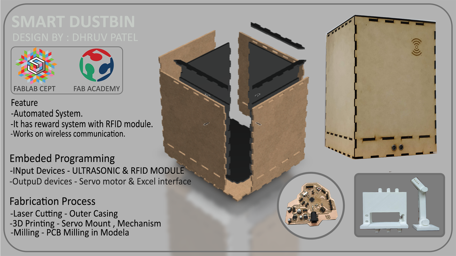
Week 20 : Final Project
In my project, I'm working on a system which can motivate people to dump their wastages on garbage bin instead of throwing it everywhere. People will get points on using this dust-bins which will be stored in their RFID
card or tag
which will be given by the shopkeeper.
Shopkeeper owns the smart bin. Points will be depend on the type ( WET / DRY ) and Amount of the garbage. Those pints can be use for getting discount in respective shop.
Smart bin system can also be used in
marketing
purpose as it contains speaker in controller which address people towards respective shop. Some Students also tried same concept about this situation.The key idea is to Reward people for making people use
Dust-bin.
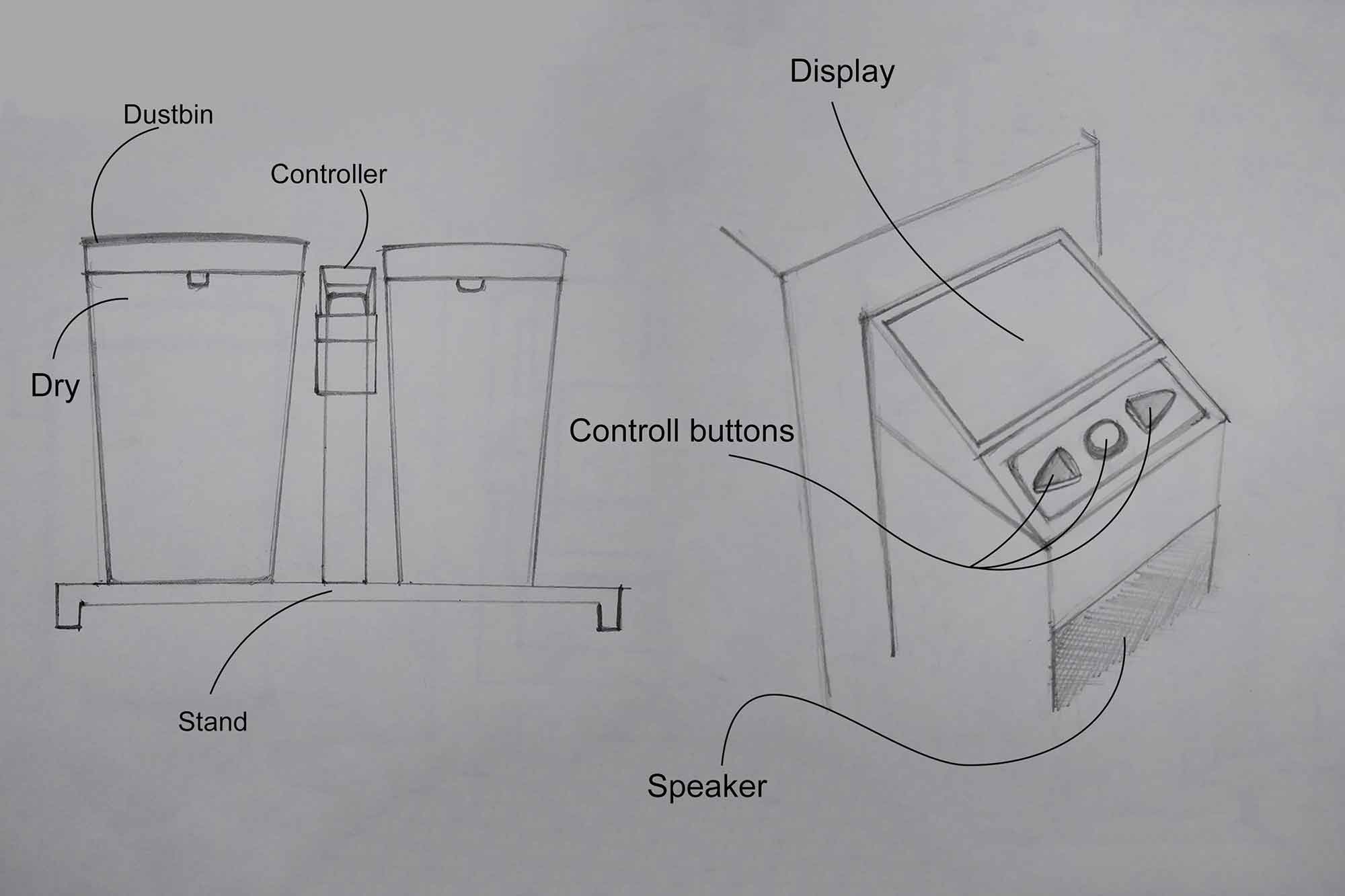
Concept model
This is a concept model I designed on week 3.
Timeline
| Task | Time |
|---|---|
| Cad design | 6/4/2019 |
| Assembly matters (joineries) | 12/4/2019 |
| CNC model | 18/4/2019 |
| Board Design | 4/5/2019 |
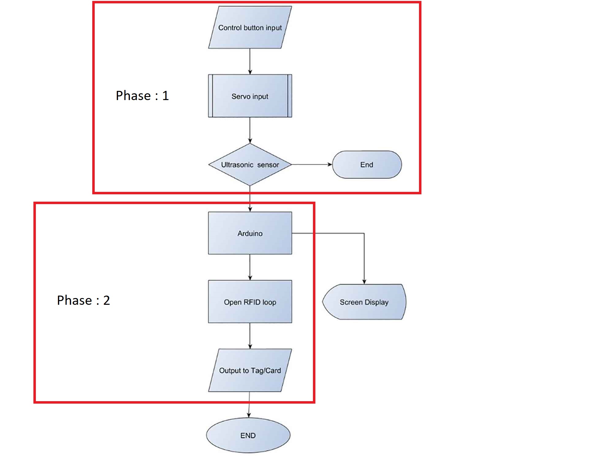
divided Project on two phases
My final project is to design an Interactive Dustbin system. I divided this project into two phases.
in Phase 1 dustbin System will be able to detect the presence of the individual, will
be able to
open and close by itself and try to manage the garbage by measuring its quantity inside. This part I am going to do in a fab lab, if I will able to complete it earlier I will work on Phase 2, if not I will keep it as my final
project.
In Phase 2, I want to make this system for commercial application in which dustbin will be owned by the Shopkeepers and for trusts who manages Historical sites. In that model, I am thinking about a
point system which will give points after use, and those points will give help to give discounts in nearby shops.
Why dividing in 2 phases ?
initially, my idea was to make One commercial model. One can check the project model on the Final project
Concept. There I described it on in detail.
The Reasonto divide into phases is I found I may have problems regarding the programming the system. I know the basics in Arduino
C and
C programming, but for programming, the RFID module will need me more learning time, though I prepared my final board the way I can easily add the RFID - module so if some time left I can work on that also.
Who has done beforehand ?
There are many examples where people tried to do automation in the dustbin. in some projects, they use the ultrasonic sensor and the servo to make the opening open or close by detecting a disturbance. In one project one used
Mic with
Arduino and servo, it will detect the sound and open the Opening. he is controlling a servo with drivers.
One project is very similar to what I am thinking for phase one. it includes an LCD module, Ultrasonic sensor, Infrared sensor with Arduino. They are using an Infrared sensor to detect the objects and an Ultrasonic
sensor to measure the quantity.
Links for all the ideas Are below :
These projects were amazing I gain a more clear perspective after watching these videos, But these are personal projects and done for only a short demonstration of the system, not for public use. What I want to implement here is I want to modify this system for Public use, People will not use/buy it if it is not looking good enough or it not reliable, and manufacturers will not manufacture if it is not convenient for sale or convenient for make.
What will I design?
As I mentioned above I wanted to make one system that is complete or semi-Automated. For phase one I am making it complete Automated, this Ultrasonic sensor will detect for disturbance or object continuously, When it
will
detect objects in between some distance it will trigger the Motor to open the dustbin..
For phase - 2 I will like to make it semi-automatic. I will not give power continuously to the Ultrasonic instead I will add one push button for the people so system can start, it is more convient udea for me for the commercial use.
Initial designs
First Picture
The below image was the first picture of what I wanted to make in the final project. I wanted to make wireless communication between the dustbin and the main controller. if someone pushes the button dust bin will open, after
throwing the trash bin will give points using the RFID - mmodule.
Full description is here.
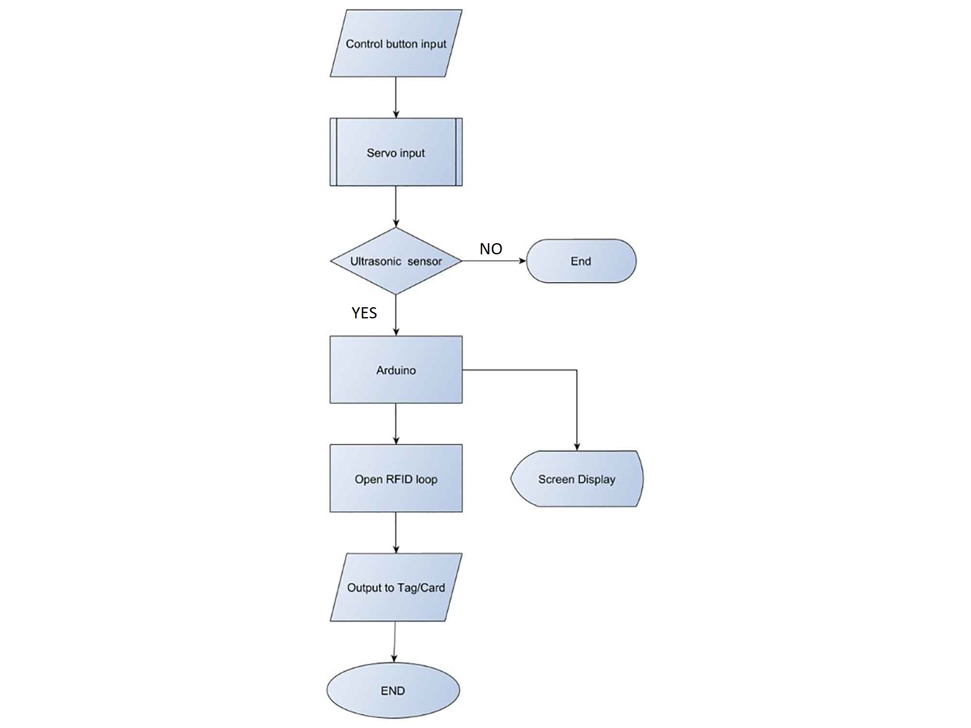
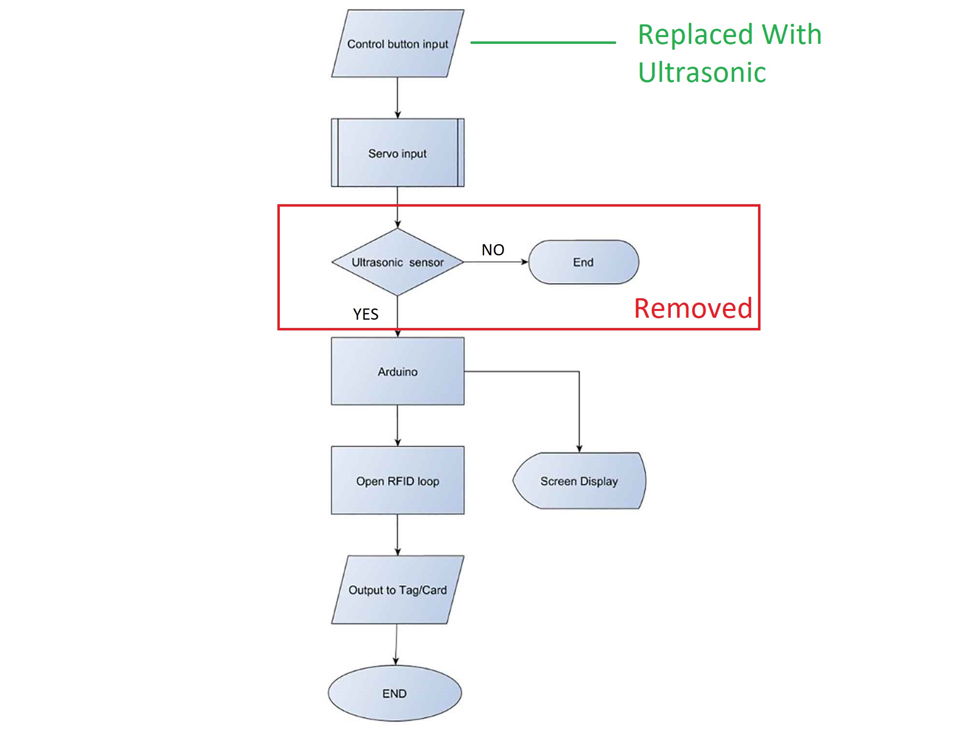
Flow chart
This is a complete algorithmic description. I divided This into two Phases. The reason I added Arduino here because I didn't know I will able to make my one! I made my new board which is able to be programmed like Arduino. the board has an ATmega 328p microcontroller. I have uploaded my board design after the Cad part below.
Some research in joineries
Apart from renders I started thinking about how my real dustbin will look like and how its joinery will be I wanted to do try some wood joinery on the dustbin especially Japanese joineries, I started doing some research one
wood dustbins and possible joints I can use in the project.
In the beginning, I went for standard joinery which is used in the woods. below are some examples!
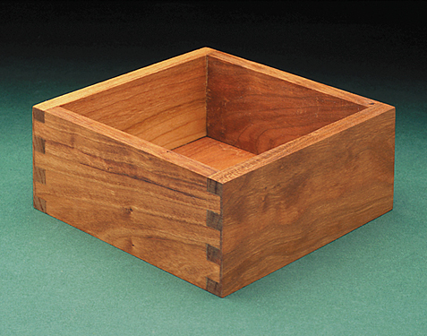
Butt joints
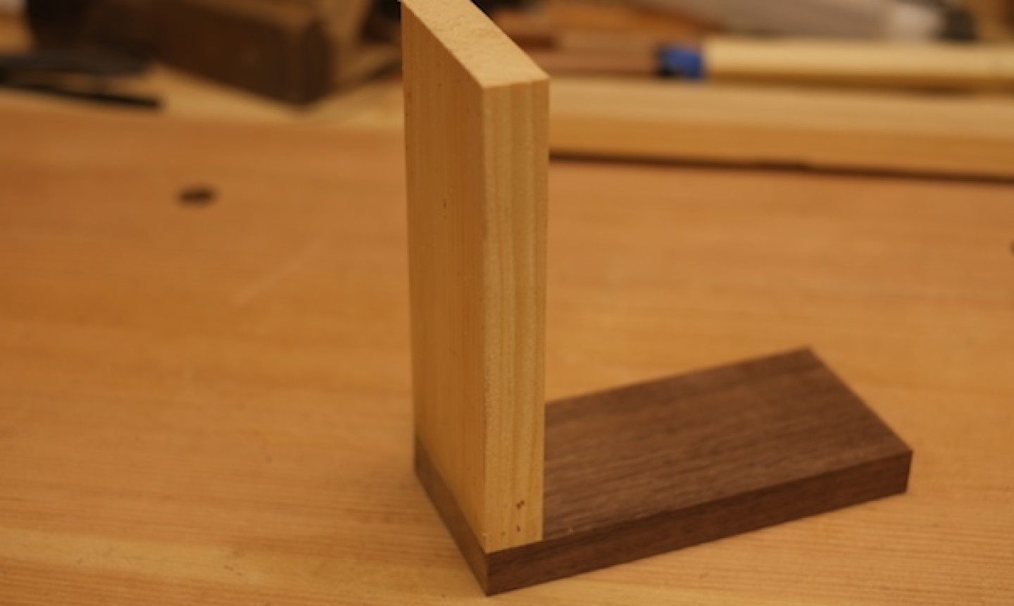
These are just two pieces of wood attached perpendicularly to each other, often with nails or screws. They can be perfectly good joints but will have no structural integrity on their own.
Butt joints can be your go-to when the work is rough or rustic or when speed matters more than looks. Just make sure your joining technique is right for the job (you might also need a metal corner bracket for extra
strength, for instance). To dress up a butt joint you can either countersink or plug your nail/screw holes.
Biscuit screws
This method involves gluing wooden “biscuits” into slots cut into the wood. It's an excellent way to hold together pieces of plywood or other engineered material, providing plenty of gluing surface as well as the strength of the
biscuits themselves.
Biscuits are good for casework and for reinforcing and lining up edge joints, but layout can be confusing until you get the hang of it.
Miter joints
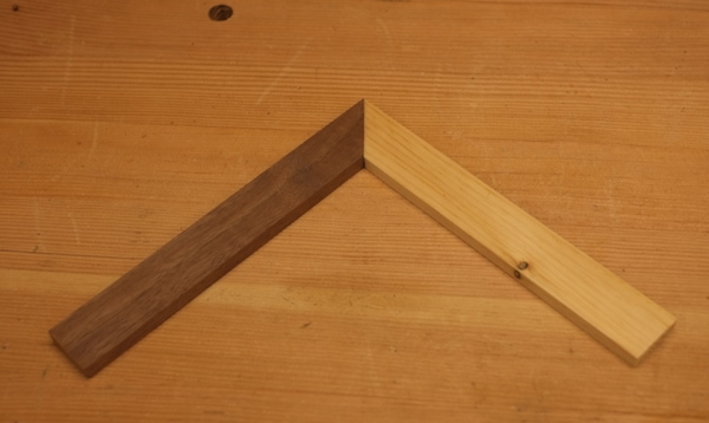
I'm including miters here because on their own they are only as strong as the glue holding them together. They have more glue surface than a straight butt joint — a plus. But the joint is still end grain, which is notorious for not
taking glue well.
Thanks to the super strength of new glues, a small box made only with miters will usually hold just fine. Still, adding a spline is a good idea.
Miters with splines look nice, so the joint itself can add to the design. The biggest negative is weakness. You will also need to take extra time to set the joint up properly so it has no gaps.
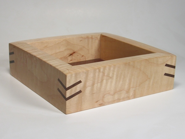
finger joints
This a good example of a ‘finger’ or ‘comb’ joint. It is ideal for box constructions and is suitable for use with natural woods such as pine and mahogany or even manmade boards such as plywood and MDF. The joint is strong especially
when used with a good quality glue such as PVA (woodworkers adhesive).
If the joint is cut accurately the ‘fingers should fit together without any gaps and the glue ensures that they are virtually indestructible. They are used for a wide range of products including jeweler boxes, cabinet construction,
kitchen cupboards and many others. (Example below - a box containing an electronic game for a young child - notice the finger joints).
image source
I decided to go for finger joint first, Reason I want to work with finger joint first because of its Simplicity and it is believed ideal for box making, I also want to try out the Biscuit joint as
well, I am thinking about testing possible joineries so I can have a better idea in my design.
Sources
Cad designs
For now, I am working on my cad model which can be used in the real world. below is the first test cad model I made it was not fully7 parametric though, giving some errors while changing the dimensions so I made another one which was more robust.
- Material : MDF
- Joints : Finger Joints
- Actual Dimensions : 350 * 350 * 500 mm
- Prototype Dimensions : 100 * 100 * 150 mm
First Cad
Second Cad
The second cad design I made was more robust for me, hard to break constraints. then I started adding sections on it, I made it two-layered so, no matter what type of garbage it is, it will stay away from the main system and wiring.
fabrication of First mechanism
After completing the Cad model I started Fabricating my components, I begin with 3d Printing parts.
3d Printed parts
- Servo mounting
- 3d printed hinge
- Rode holders
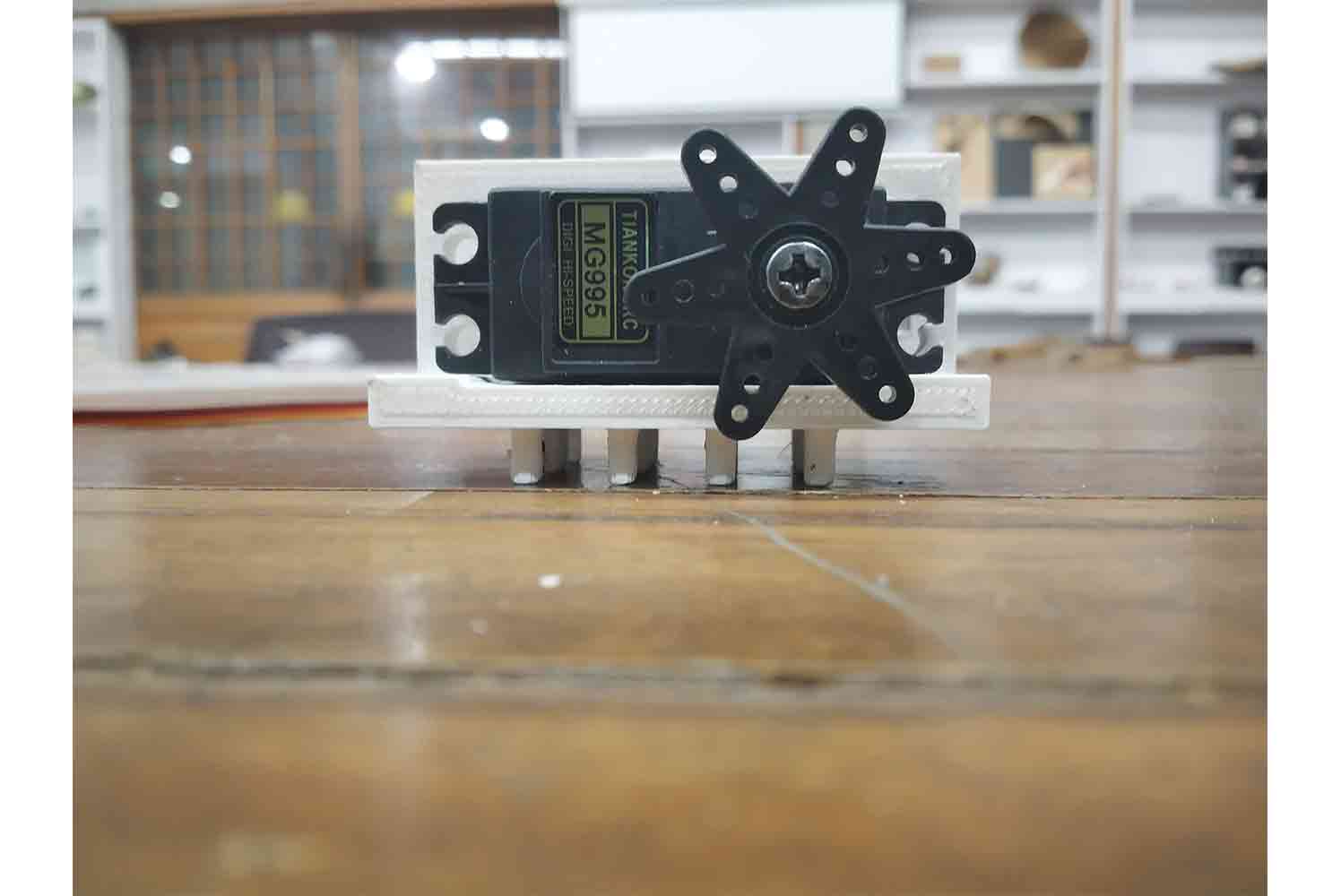
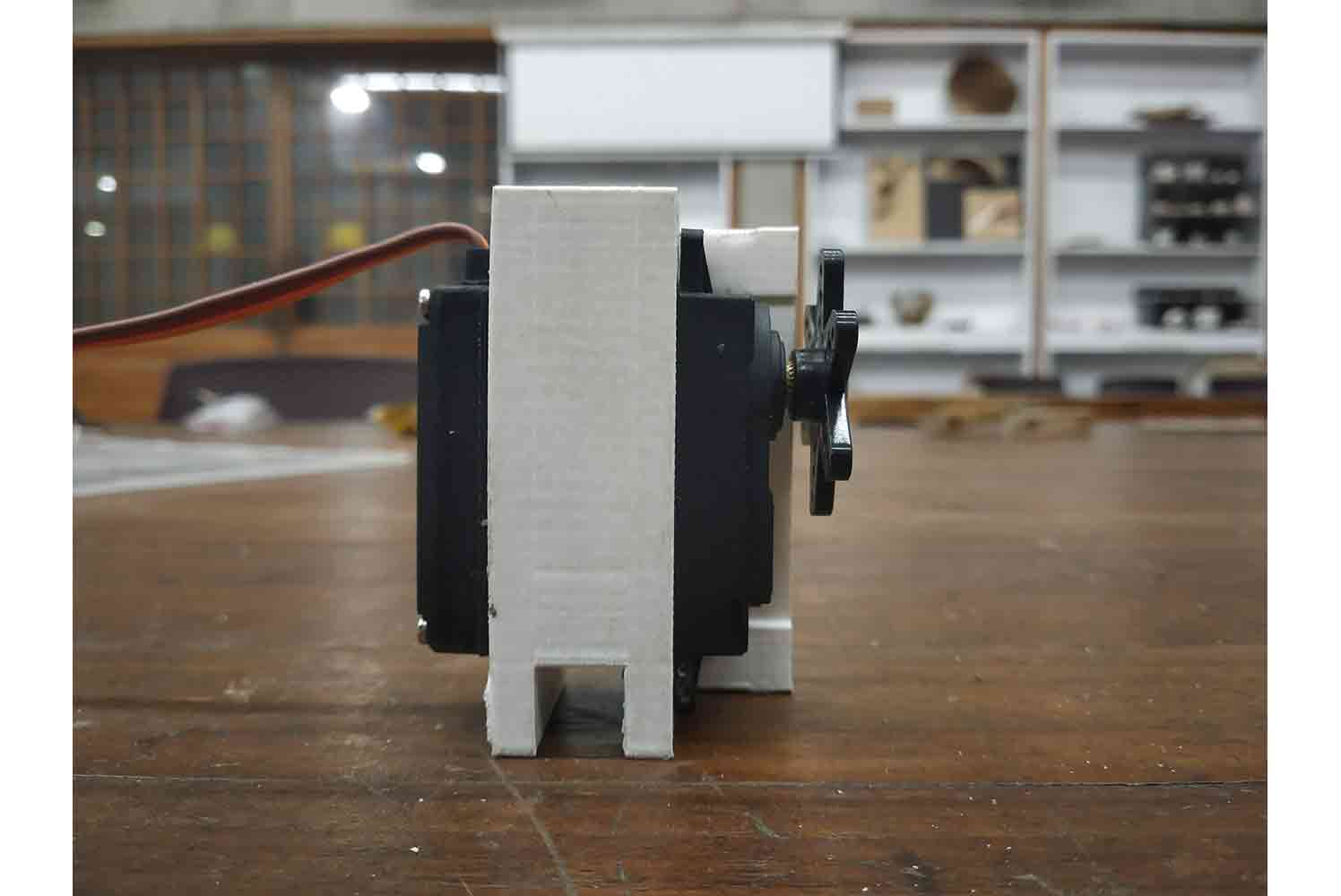
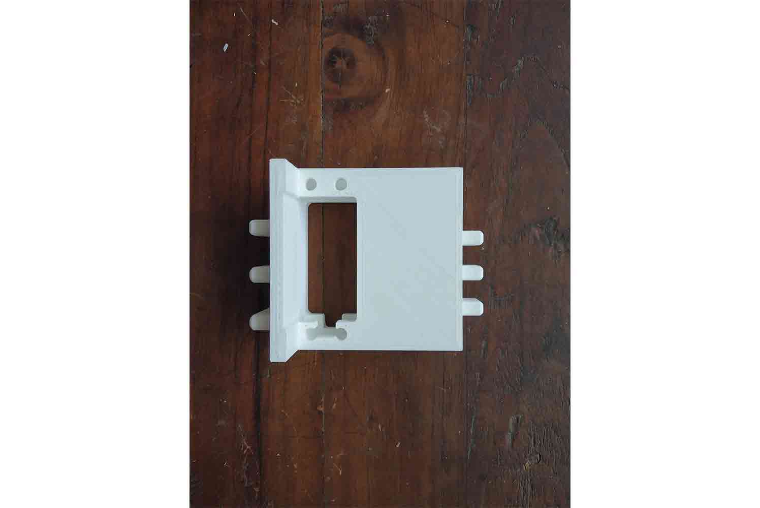
Servo mount
I designed Servo mount for Tianko - MG995 180 degree servo. it's designed the way its legs go between the slots of 6 mm MDF laser sheet and hold the servo by friction!
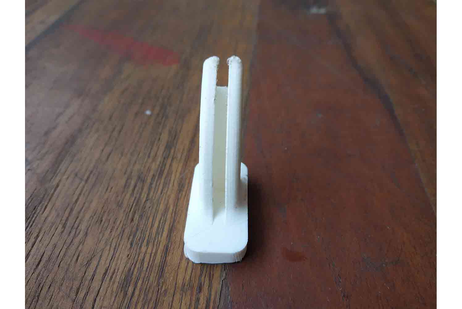
Design of shaft holders
It will keep the Shaft align with Servos at the Center of Rotation Axes.
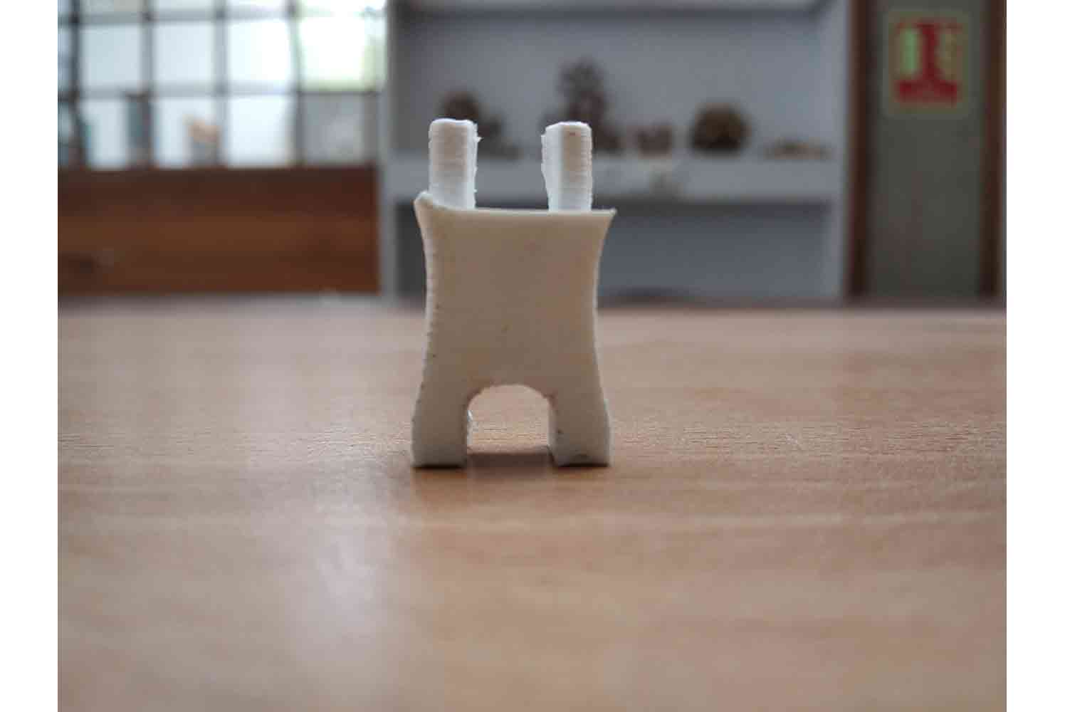
Little demp of their placement on bottom
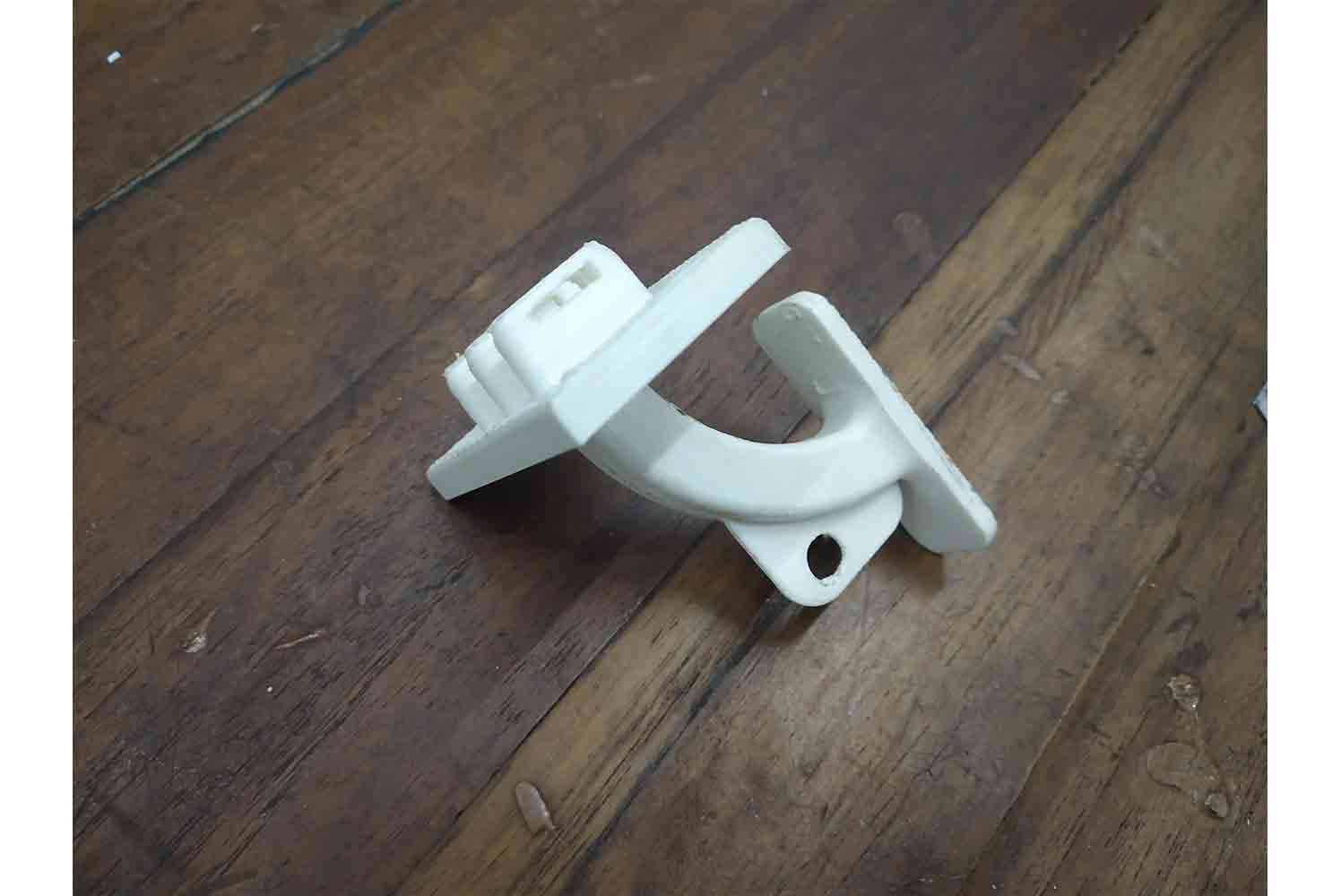
3D printed Hinges
Initially, I don’t want to use any mechanical part on the system, I wanted all my joineries laser cut or 3d printed. so I designed this hinge which will take up the flapper.
Slider
Slot
Demo
It will be something like this!
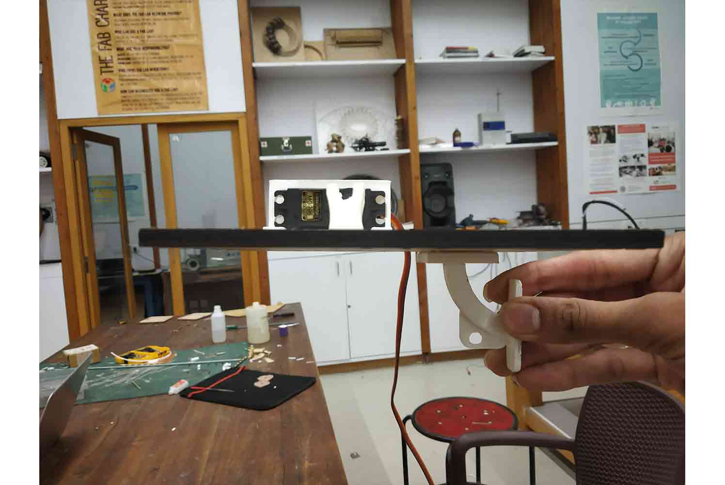
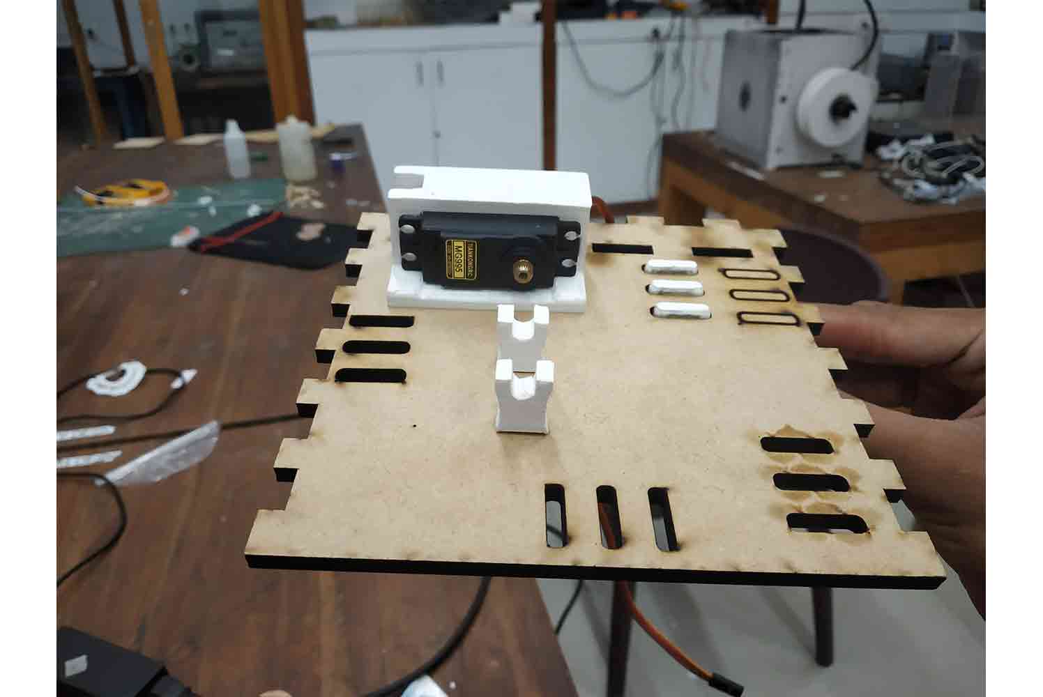
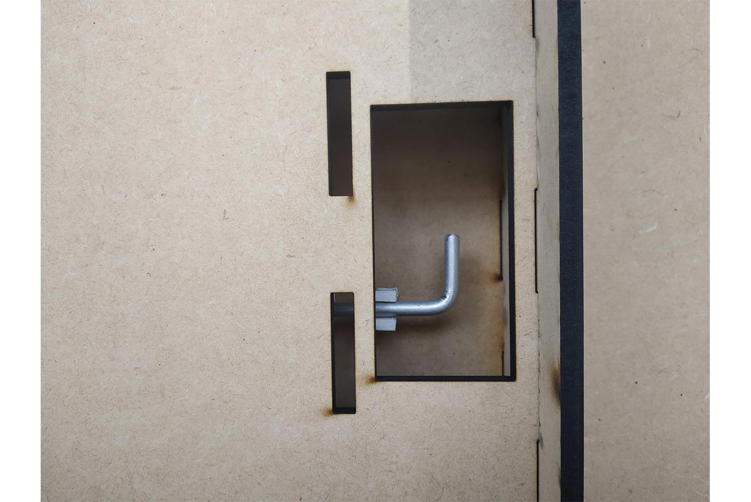
Laser cut panels for test
Below The middle Panel
Below two pictures Explain servo mounting Below the middle panel! one can also see on cad model!
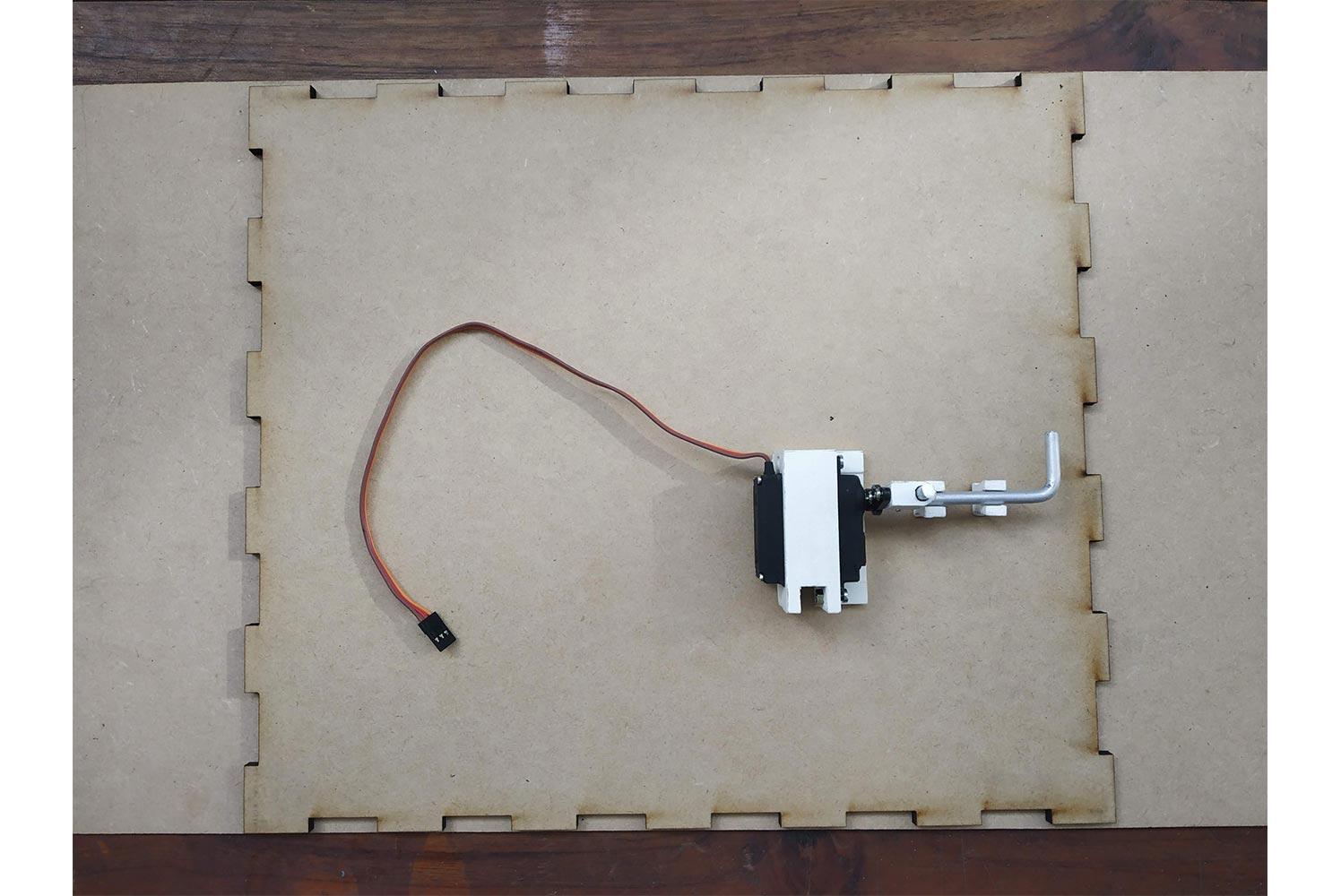
Demo Assembly
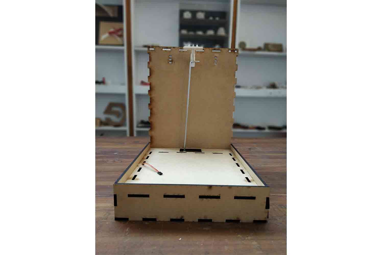
Mechanism test without Flapper
It worked as I assumed Without Flapper, so the mechanism can work!
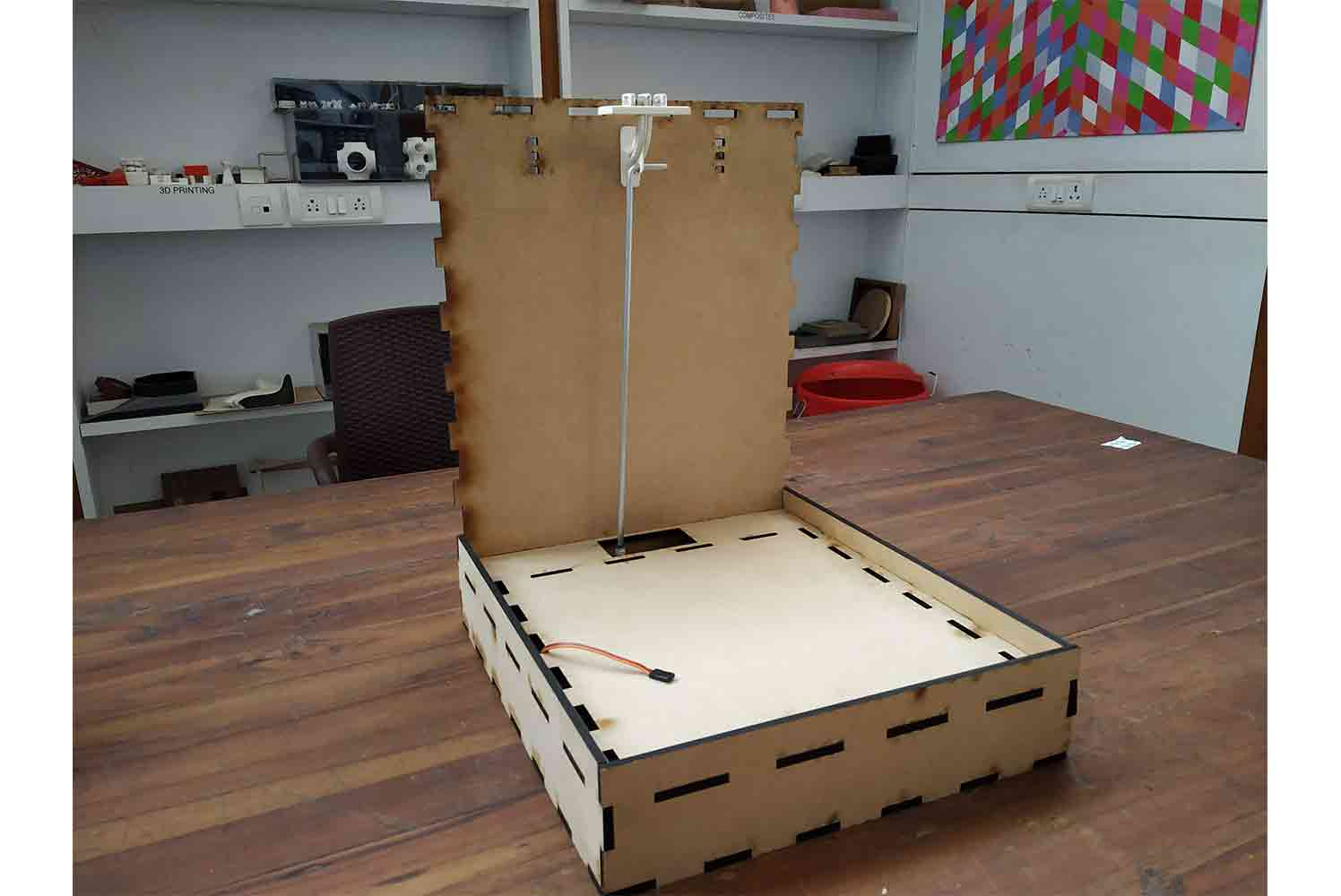
Failure when Flapper is Attached
It failed when I attached Flapper!
Failure
After First Mechanism failed, I started working on the new mechanism, I knew servo was capable enough to lift the 3 mm MDF flapper, I had an idea of servos load capacity, somehow I made some mistake somewhere.
Failure Reasons
- I half the torque by base Z-Rod Design
- I put the Pivot point of vertical rod where moment is maximum and it cant be go up.
- third reason is not related with design it is related with time, I made so many inter related components that it will be hard to assemble and work with
Solution
- Transfer the load directly from the servo to Flapper
- Reduce the Components needed if it can
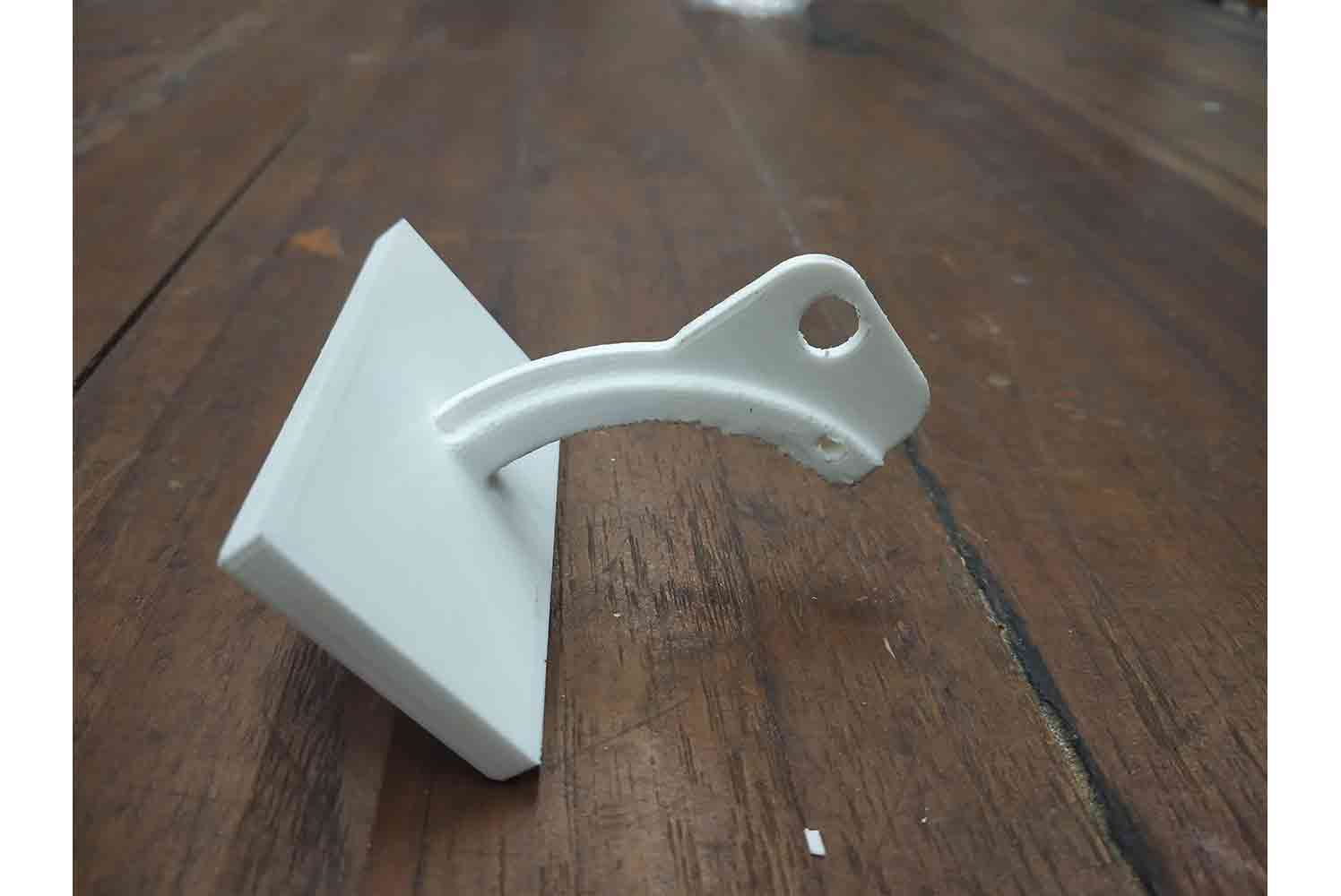
Fabrication of second Mechanism
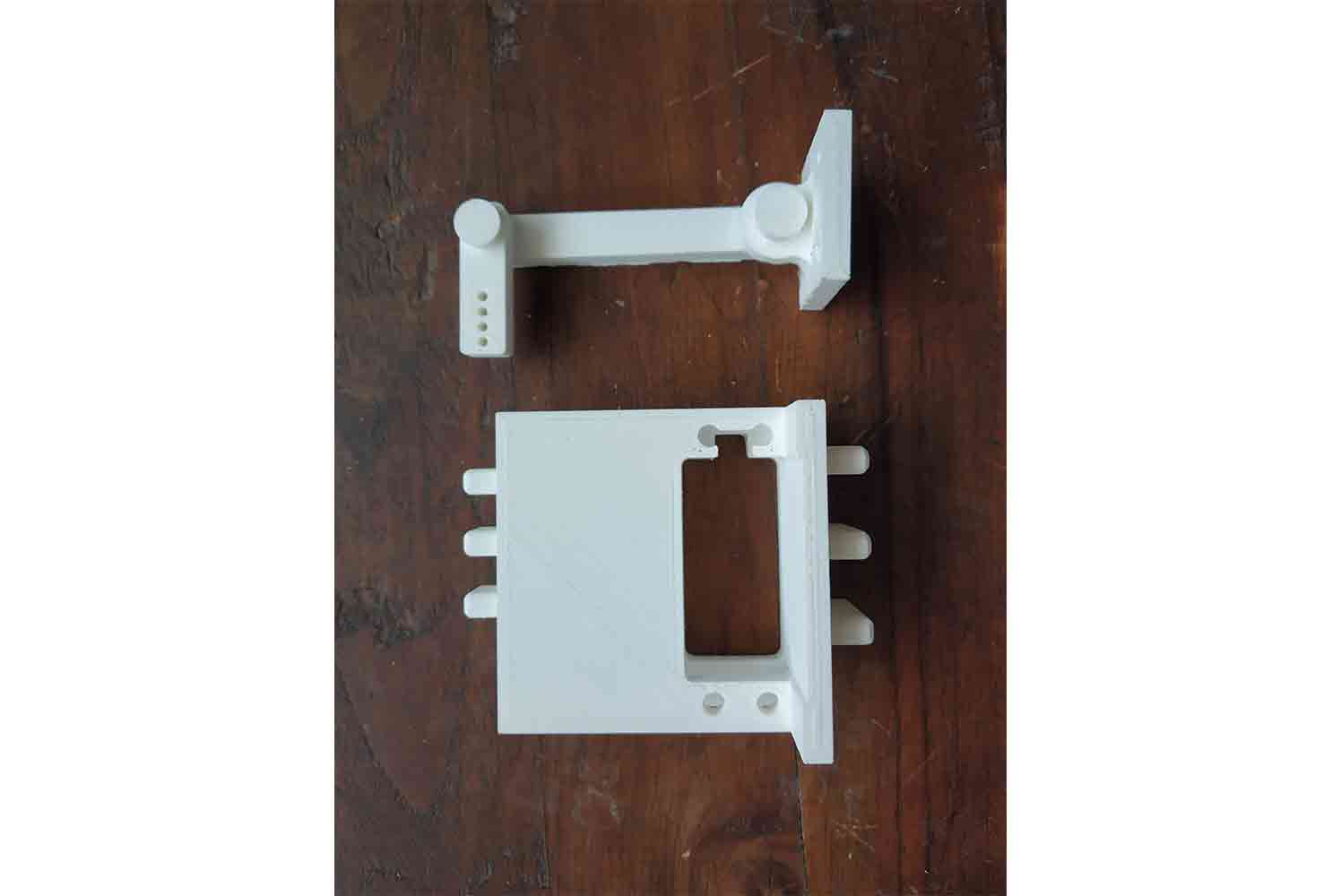
3d Design printed parts
- Second design oF Servo Mount
- Flapper mechanism
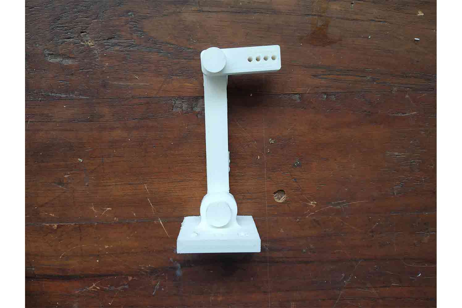
Modified servo mount
I modified the servo mount by increasing its length, so the servo horn does not touch Panels.
Flapper mechanism
The Flapper mechanism will directly connect the Servo to the Flapper. it also looks like 'One' - One element.
Servo mounts placement
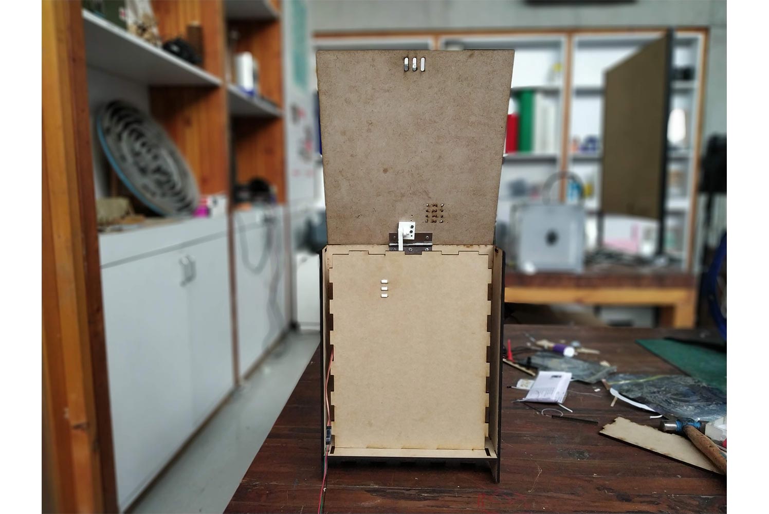
Laser Cutting of Final Panels
After confirming the Servo mount is good in its position I started laser cutting the Final Panels.
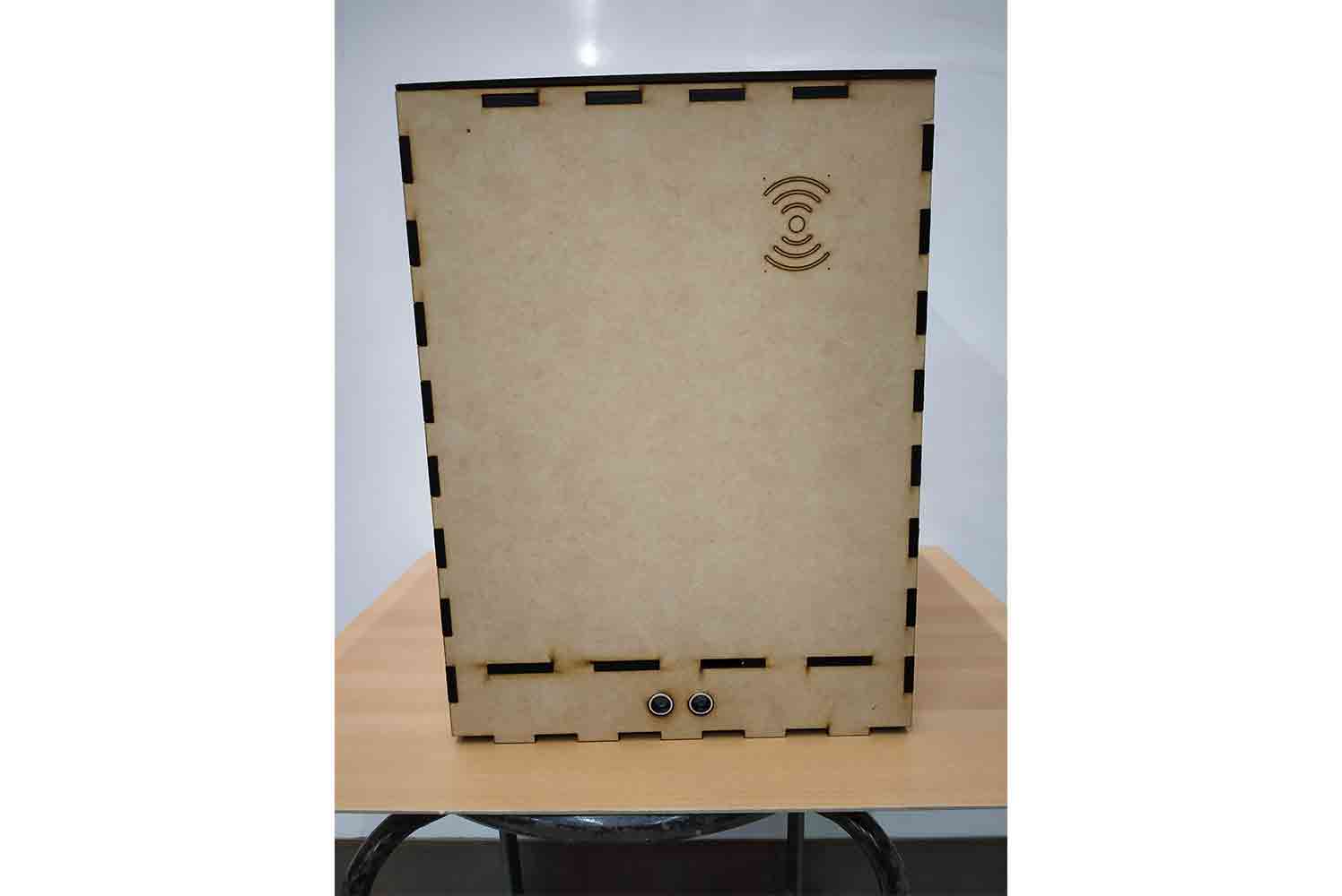
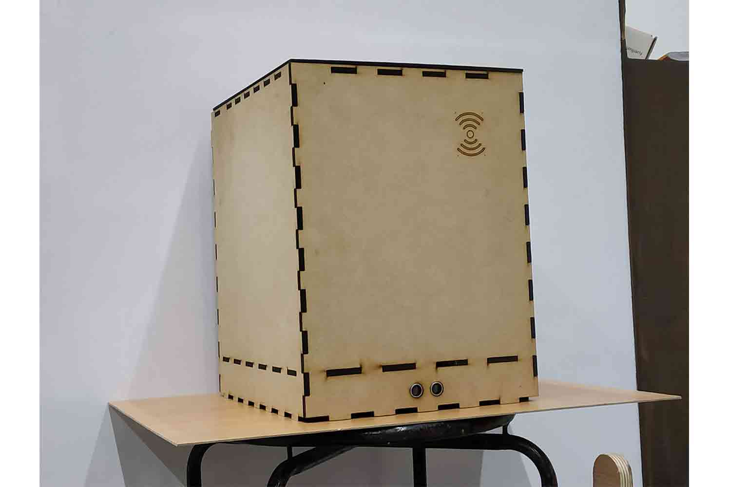
Front outer panel
In front Outer panel, the ultrasonic sensor mounted below the position where I thought it will get the maximum surface of Human legs to detect! and Behind the RFID tag, the RFID reader is mounted!
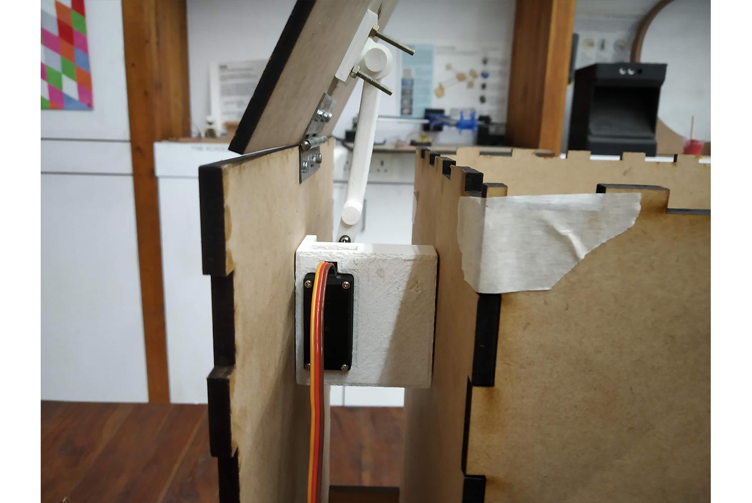
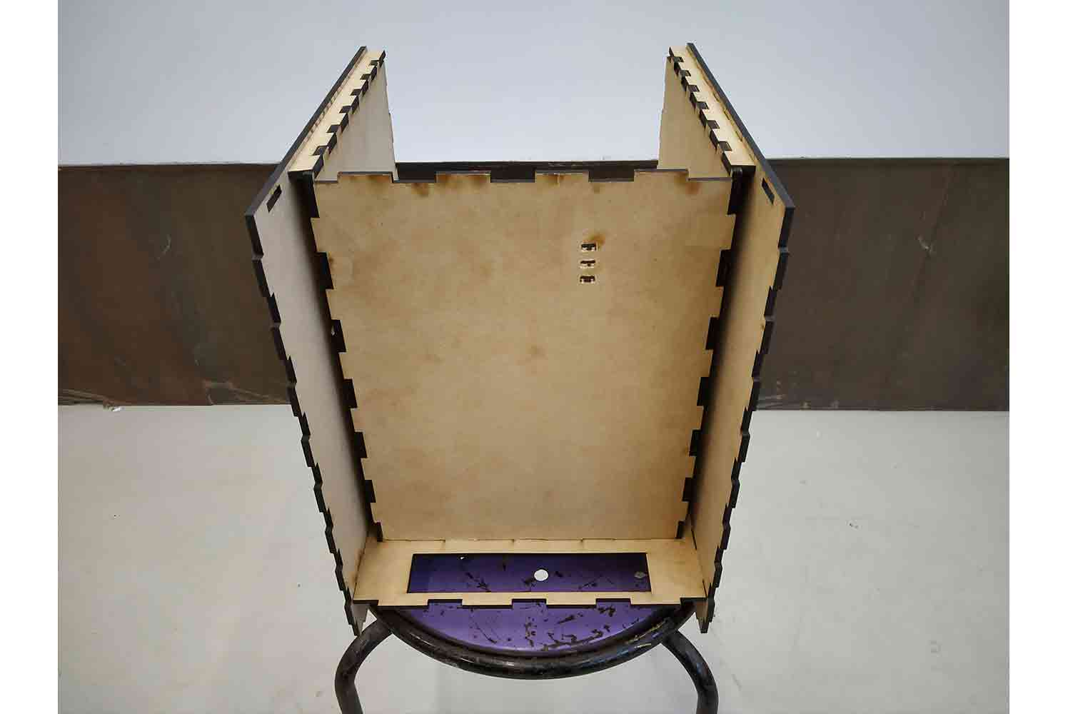
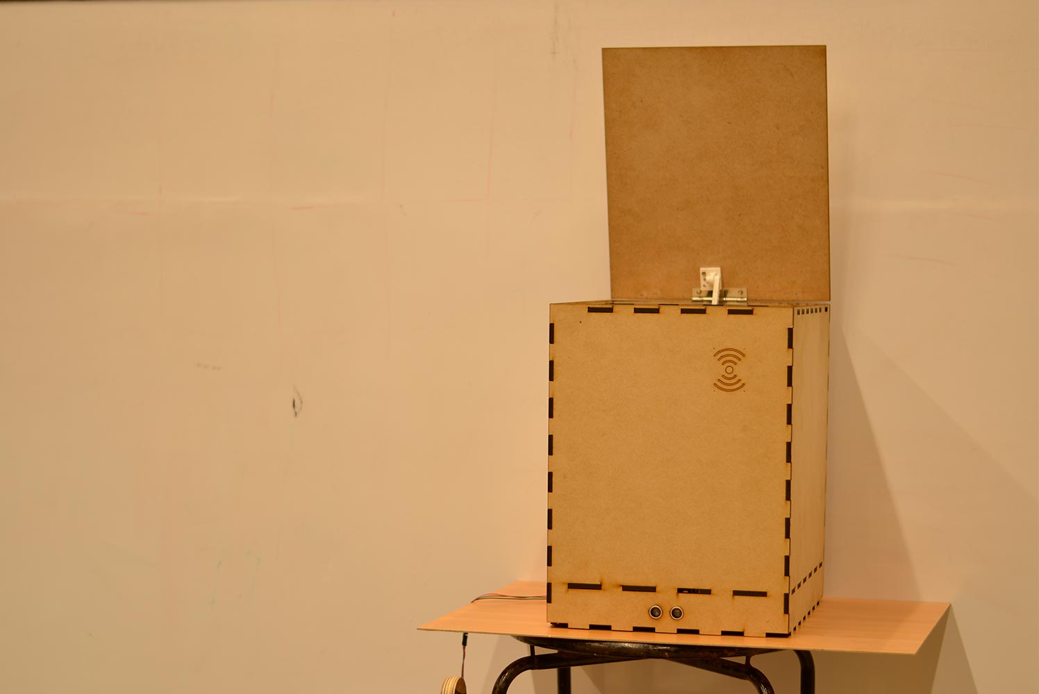
Back Section
in the Back section, there is little space in between servo will be fitted, it is a very strong solution for servo mounting, learned Hard way from machine design.
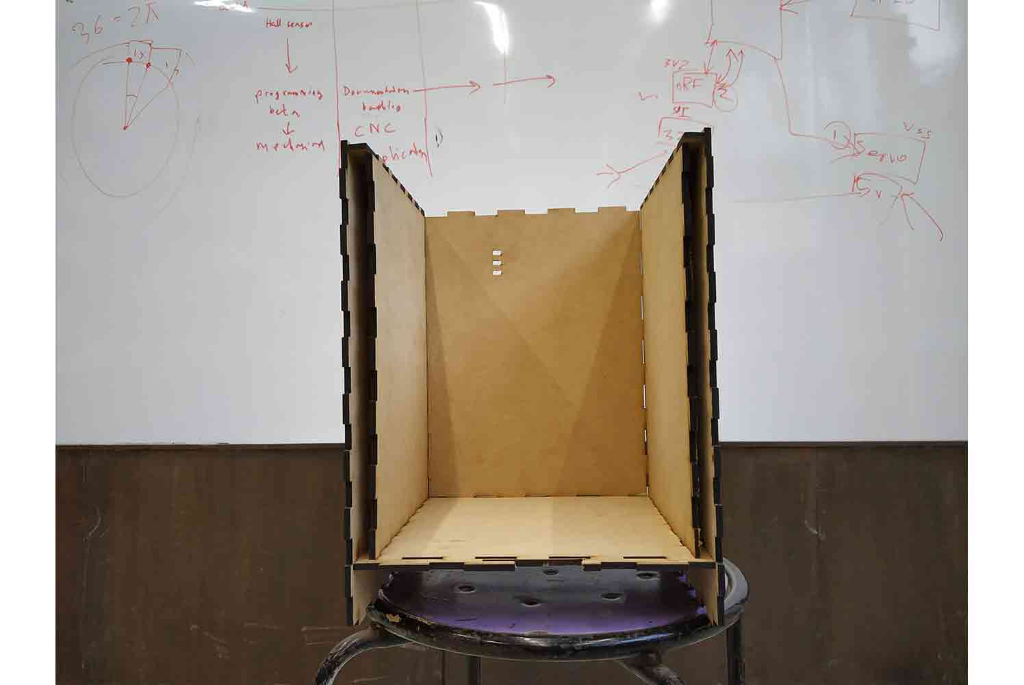
Front inner section
Space where dump will be thrown in.
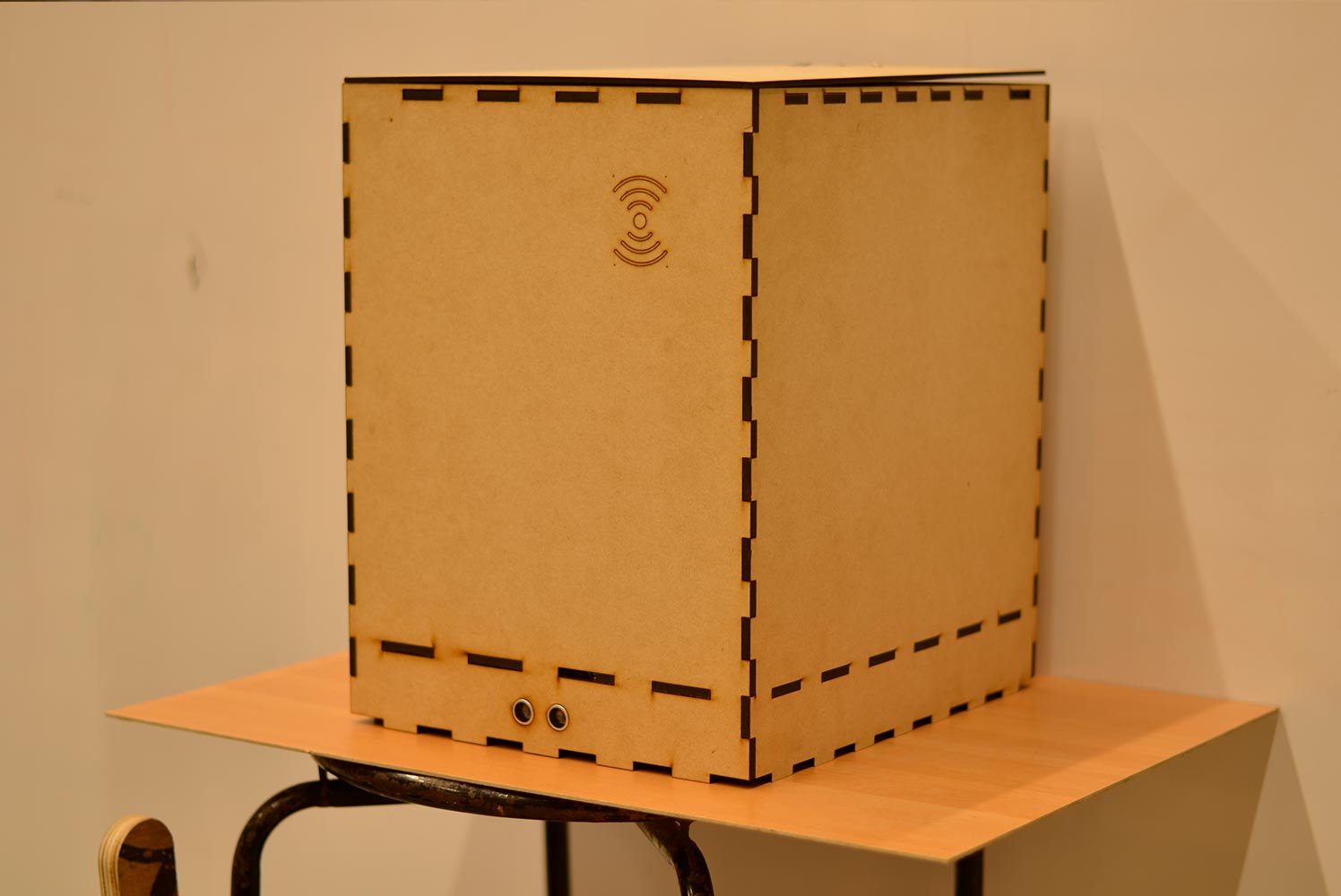
Final Clicks
Mechanism testing Video
Electronics Part
Board Modifications
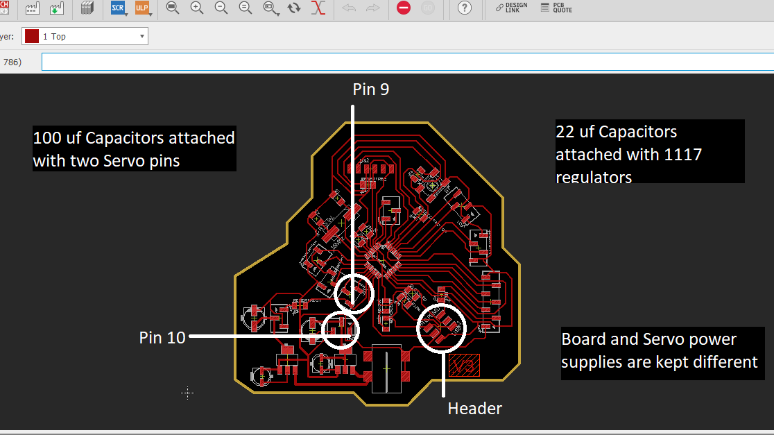
As I talked about my final board in week 11 and week 16 I gave two power supplies to my board and I though RFID needs only SPI pins I was not sure
it will need two PWM Pins to communicate and need to have 3.3 power supply.
I was told that this two extra Pins can be any Extra PWM pins and standard PWM pins which are connected to RFID are 9(RST)
and 10(SS), these pins were nearer to the SPI header, so I made one shield which will connect this pins and connected 1117 regulator to Vcc of RFID pin.
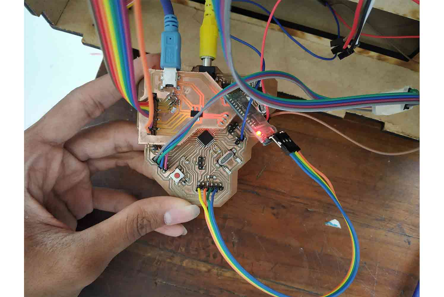
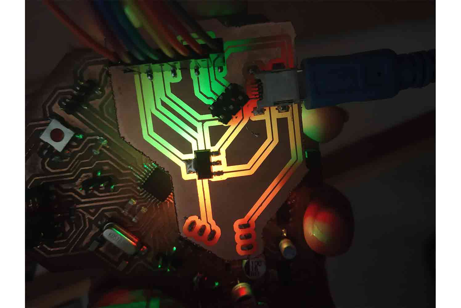
Below is Images of Wiring and Glow it is making, its above
RED and GREEN led making it beautiful.
Final Code
I Have Explained Final Code in the comments Below, In summary, I am working with Servo, Ultrasonic sensor, and RFID module. I thought something like the below image in initial thinking and most of it I am able to achieve so far, yes Things like Displays I would like to use on a bigger model and I replaced input to Ultrasonic sensor to give more Automation. but I couldn’t use the second ultrasonic system so far. problem Was I couldn’t understand how I will trigger the RFID module by giving some instance ultrasonic value, because dump will be triggered by inner ultrasonic at the instance, and as a user, I can throw dump and use a tag at the same time, I knew it may have some solution but as a time constraints, I went for a less promising solution.
Initial thinking
Solution was Delay
Freezing the system for Five minutes after one regarding was the solution. I triggered the Rfid module automatically after the servo code is finish, Code executes from top to bottom and it will freeze for five minutes. So the user will not cheat to get points!
Testing RFID code
  #pragma GCC optimize ("O2")
  // for opti,ization of code

  #include <SPI.h> // For SPI Pins add spi library
  #include <MFRC522.h> // for setting RFID interface add MRFC522 library
  #include <Ultrasonic.h> // for ultrasonic Add ultrasonic library
  #include <Servo.h>  // add servo library

  Servo myservo; // define servo
  Ultrasonic ultrasonic(A4, A5) ; // define (trig,echo)

  int pos = 160; // defined initial position of servo

  int distance; //  defined distance for ultrasonic

  // setting up interface for (PWM pins needed) for RFID, it will help in communicate
  #define SS_PIN 10 //RX slave select
  #define RST_PIN 9 // rst pin

  MFRC522 mfrc522(SS_PIN, RST_PIN); // Create MFRC522 instance.

  String card_ID=""; //card UID

  //Add as many cards you want
  String Name1="14710721526";//first UID card
  String Name2="21799093";//second UID card
  String Name3="8159175206";//third UID card
  String Name4="13937143185";//fourth UID card
  String Name5="2174114201";// fifth UID
  String Name6="254161178115";//and so on.

  // Arrays to run rfid LOOP
  int NumbCard[6];//the number of cards. in my case I have 6 cards.
  int j=0;  //increased by one for every user you add
  int statu[6];//the number of cards. in my case I have 6 cards.
  int s=0;  //increased by one for every user you add


  String Name;//user name
  long Number;//user number
  String ExcelName="Logs"; // given names
  int L=0;
  int n ;//The number of card you want to detect (optional)
  int ID=1;
  void setup() {
    myservo.attach(5); // servo pin

    Serial.begin(9600); // Initialize serial communications with the PC
    SPI.begin();  // Init SPI bus
    mfrc522.PCD_Init(); // Init MFRC522 card

    // for excel sheet
    Serial.println("CLEARSHEET");                 // clears starting at row 1
    Serial.println("LABEL,ID,Date,Name,Number,Card ID,Time IN");// make four columns (Date,Time,[Name:"user name"],[Number:"user number"])

    delay(200);
     }

  void loop() {

    // Pass INC as a parameter to get the distance in inches
    distance = ultrasonic.read(); // getting distance
    //Serial.println("distance : ");
    if(distance>70 && distance<80)  // and condition, if Distance is between 70 and 80 cm, servo will open
    {
  for (pos = 160; pos >= 80; pos -= 1) { // goes from 160 degrees to 0 degrees
      myservo.write(pos);              // tell servo to go to position in variable 'pos'
      delay(15);

    }
    delay(2000); // Flapper will open for 2 sec,
    for (pos = 80; pos <= 160; pos += 1) { // goes from 0 degrees to 160 degrees
      // in steps of 1 degree
      myservo.write(pos);              // tell servo to go to position in variable 'pos'
      delay(15);
    }
    }
    else
    {
       myservo.write(160);   // default position
      }
    // servo code ends now
    // RFID code will run now


    //look for new card, if card is not detected, code will return to loop start
     if (! mfrc522.PICC_IsNewCardPresent()) {
    return;//got to start of loop if there is no card present
   }
   // Select one of the cards // if card serial returns 0 then it will return to start of the loop
   if (! mfrc522.PICC_ReadCardSerial()) {
    return;//if read card serial(0) returns 1, the uid struct contains the ID of the read card.
   }

   for (byte I = 0; I < mfrc522.uid.size; i++) { // for running the loop equal to the card id
       card_ID += mfrc522.uid.uidByte[i]; // getting the card id
   }

        Serial.println(card_ID); //Uncomment this line to scan the card ID and appear it on Serial monitor.

         if(card_ID==Name1){
         Name="Dhruv Patel";//user name
         Number=1;//user number
         j=0;//incresd by one for every user you add
         s=0;//++1
        }
        else if(card_ID==Name2){
         Name="Maharshi solanki ";//user name
         Number=2;//user number
         j=1;//++1
         s=1;//++1
        }
        else if(card_ID==Name3){
         Name="cido3";//user name
         Number=789101;//user number
         j=2;//++1
         s=2;//++1
        }
        else if(card_ID==Name4){
         Name="cido4";//user name
         Number=789101;//user number
         j=3;//++1
         s=3;//++1
        }
        else if(card_ID==Name5){
         Name="cido5";//user name
         Number=789101;//user number
         j=4;//++1
         s=4;//++1
        }
        else if(card_ID==Name6){
         Name="cido6";//user name
         Number=789101;//user number
         j=5;//incresd by one for every user you add
         s=5;//++1
        }
        else{ // code will jump below two loops is no conditions is fulfilled, suppose user is new or forgot to register
            goto cont;
       }


        if(NumbCard[j] == 1 && statu[s] == 0){
        statu[s]=1;
        NumbCard[j] = 0;
        Serial.print("DATA,");//send the Name to excel
        Serial.print(ID); // local ID
        Serial.print(",");
        Serial.print("DATE");
        Serial.print(",");
        Serial.print(Name); // Name of User
        Serial.print(",");
        Serial.print(Number); //send the Number to excel
        Serial.print(",");
        Serial.print(card_ID); //send the card ID to excel
        Serial.print(",");
        Serial.print("TIME");
        Serial.print(",");
        Serial.println("");
        ID=ID+1;
        n++;//(optional)
        }
        else if(NumbCard[j] == 0){
        NumbCard[j] = 1;
        statu[s]=0;

        Serial.print("DATA,");//send the Name to excel
        Serial.print(ID);
        Serial.print(",");
        Serial.print("DATE");
        Serial.print(",");
        Serial.print(Name);
        Serial.print(",");
        Serial.print(Number); //send the Number to excel
        Serial.print(",");
        Serial.print(card_ID); //send the card ID to excel
        Serial.print(",");
        Serial.print("TIME");
        Serial.print(",");
        Serial.println("");
        delay(30);
        ID=ID+1;
        }
        delay(1000);

  cont:
  delay(1000);
  card_ID="";


  //if you want to close the Excel when all card had detected and save Excel file in Names Folder. (optional)
  //
  //if(n==4){
  //    ExcelName +=L;
  //    L++;
  //    Serial.print("SAVEWORKBOOKAS,");
  //    Serial.print("Names/");
  //    Serial.println(ExcelName);
  //    //Serial.println("FORCEEXCELQUIT");
  //    Serial.println("CLEARDATA");
  //    n=0;
  //    ID=1;
  //    ExcelName="Logs";
  //    }


  delay(5000); // System will be Freeze for 5 sec
  }
RFID and PLX-DAQ
I Prepared the code to get the data of the RFID tag but it should be represented in the shopkeeper's Database for the point system, I was finding that solution with code and I Got one I used the PLX-DAQ interface which takes data via COM ports by which any Serial Data Transfer device is connected and Arranges it on Columns of the Excel
sheet!
I Suggest one to download PLX-DAQ version 2. first version has limited com ports so the option for needed
com port may not be there, in the second one, one can write com ports number! In my case, I needed wireless device and it should be easily connected with Computers I choose Bluetooth for That!
- I took the data from RFID reader
- Transfered it thought hardware serial (Rx, Tx)
- Bluetooth Transferred it to Computer PLA-DAQ interface by Selecting Com-port
Interface of Shopkeepers : Excel
Final project Video
Slide
Conclusion
It is the last time I am typing any Conclusion regarding My weeks! I will give my Conclusion about my whole fab academy experience though! Fab academy has succeeded to give me what I wanted to do from the last couple of
years. I had no making experience back so far, never new any machines even simple Jigsaw one, never used a hammer in life (little embarrassing)! in short, never done anything related to making when I started doing cad I knew I
needed this experience I intended to design things which can help in real-world and as I told I had no product design experience of the real world. So the experience was Greatfor me!
I am not saying I had always a good time in my fab academy and things worked out as I wanted to, I can't even remember things which I made it work in the first try! what I remember and being happy about are the things which I tried and
made it happen Somehow, like a Maker.
Hope I get the chance to work with Fab academy Again!
