Getting Started with GIMP
Many website stated that GIMP has all the functionality that Photoshop has.
Since photoshop was the software that I used a lot through my Architecture study, I wanted to explore GIMP. Thus I started with GIMP
GIMP stands for GNU image Manipulation Program. The advantage is that it is open source and cross platform software. You can download GIMP from
here.
Then I referred various tutorials which made me understand the User Interface of GIMP which looks like Photoshop but the way it function was quite different in some sense.
GIMP Basics
How to make a Logo using GIMP
GIMP Tour
Raster Image using GIMP
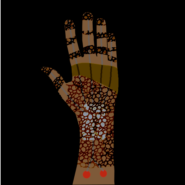
You can see the final output that I achived using GIMP.
Process
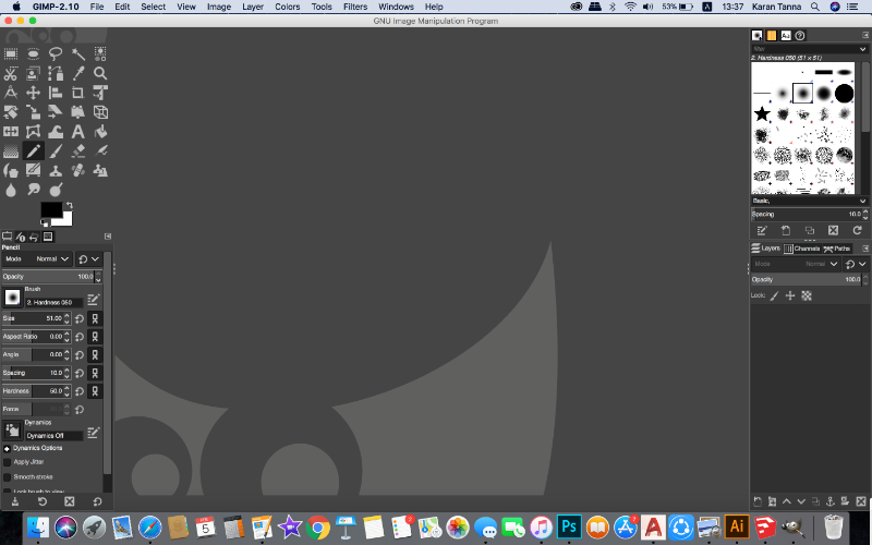
After opening GIMP, the screen looks like as given below.
(Nice premium looking black theme with intutive tools and file menu.)
Go to File > New
A new box will open with many options as below.
Note:(Here I found that you can’t actually do custom canvas ratio, it opens with default ratio. I wanted to make square canvas but I could only change layer size annd not canvas size. )
I guess GIMP treats every layer as new and we have to manually change the size of each everytime.
I was uneasy with it. Thus I turned up on Photoshop. It will look like as given below created file with setting below.
The advantage is that it has many print and web options and easy to access. Even a layman can use.
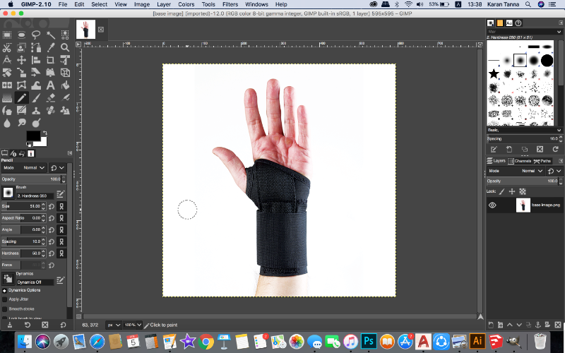
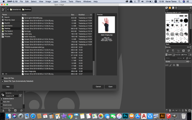
I opened the file that I created. File > Open (select file and enter)
Note: You should always work in layers. Different layer for each object.
Photoshop creates new layer for each entity. But GIMP doesn’t so you have to manually make it.
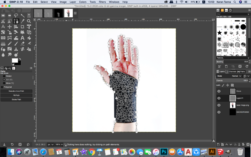
I found Path tool to be the most useful tool. I selected Path tool from tool bar on the left.
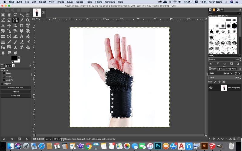
Then I traced path to make the wrist brace/support for my project. As about.
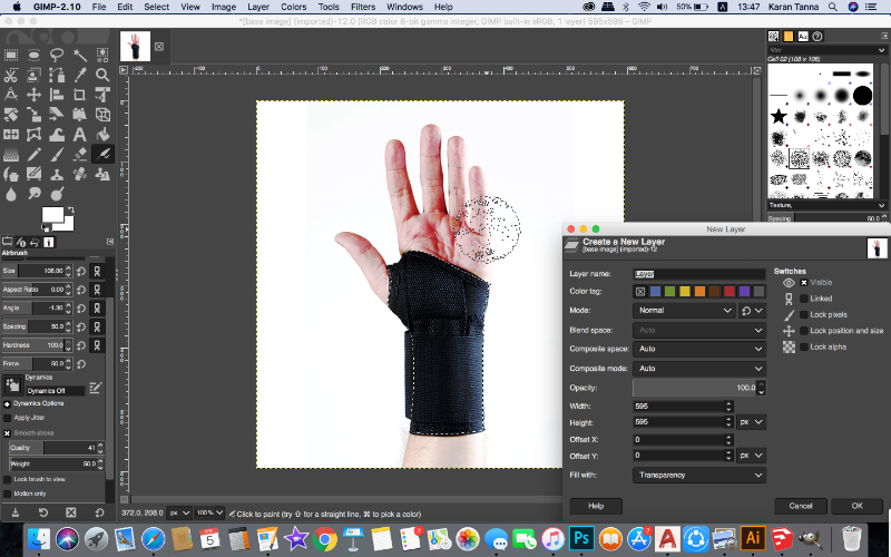
Then I used brushes too to fill. Before that do not foreget to make new layer.
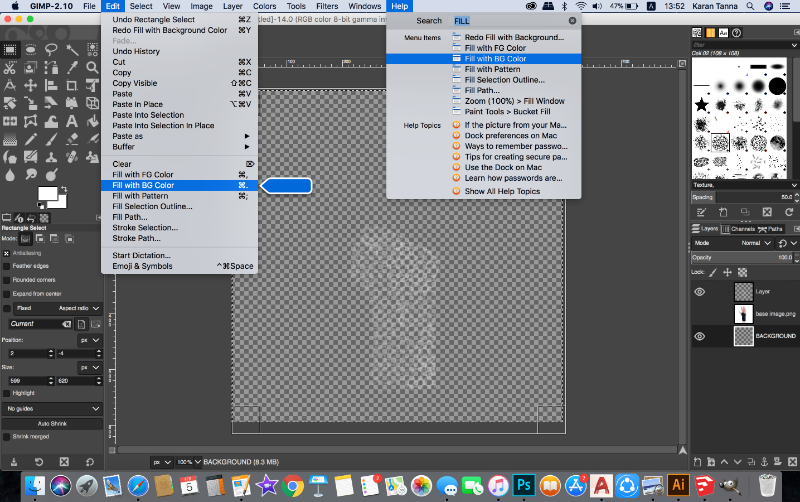
Now as we don’t have backgrounnd layer, we need to create one. Add layer from right bottom corner, and drag it to bottom.
Go to Edit> Fill with BG colour. (colour on back is background colour in dual colour cards.)
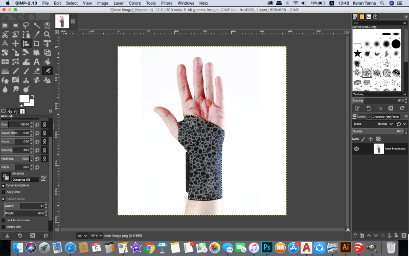
Now add new layer and select path tool again.
Trace the path and make boundary of hand as shown.
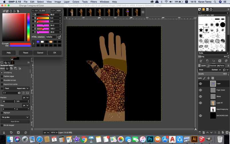
Then Fill it with Bucket tool on left tool bar with desired colour.
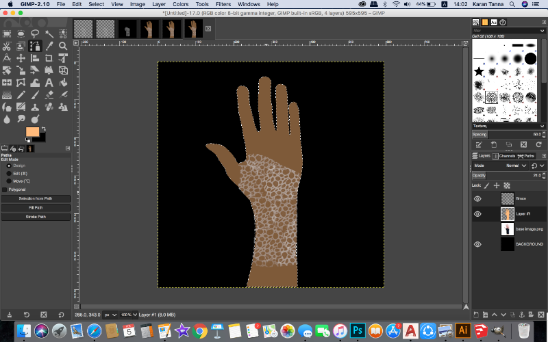
Put that layer below brace layer and subract the brace layer to generate above effect.
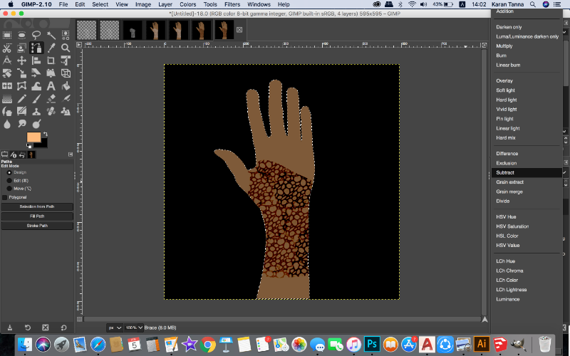
Note: You can do various things with various blend mode. Subtract mode subtracts given colour from other colour.
Make new layer and select the shape as given below and then fill it as below.Then subtract it.
Now select Ellipse selection tool and hold shift and make two circles as given, After making Sensors layer.
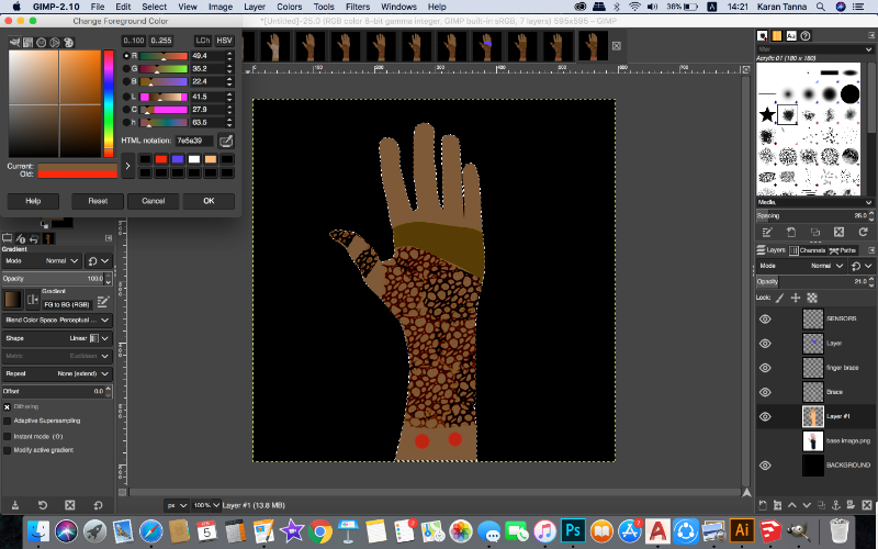
Now fill it with colour as given
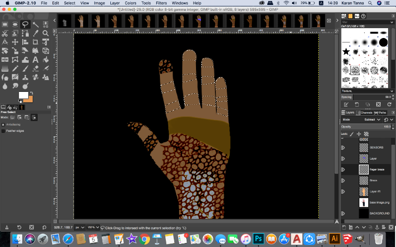
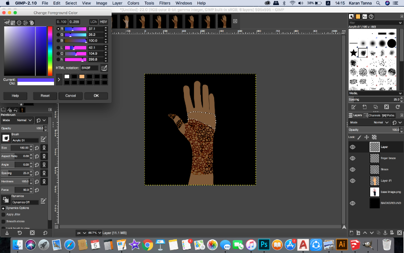
Then onwards select the parts shown below and make
finger brace layer and fill it with brush we used previously.
Also make a box with any selection tool and fill it as given with pale blue.
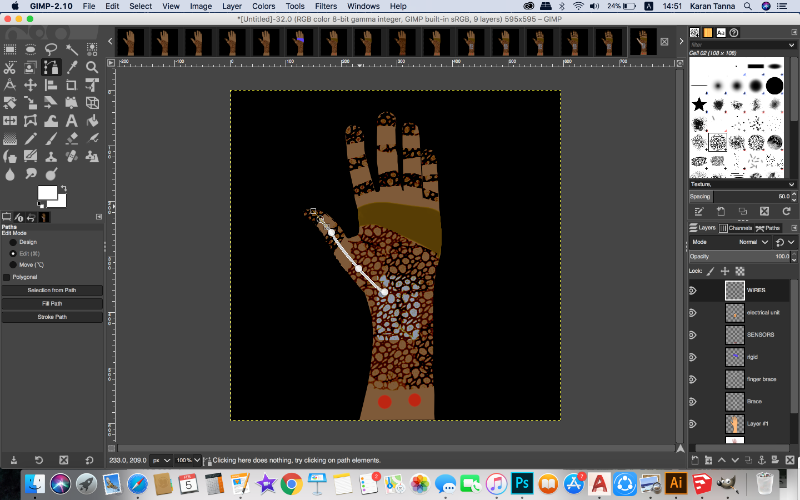
Now using path tool, Connect lines from electrical box to all the finger braces, in new layer called cables.
Now go to : Edit > Stroke path. Select the thickness that you want and stroke it.
Now use Blend mode called LCh Chroma and make opacity of Wires layer 75%.
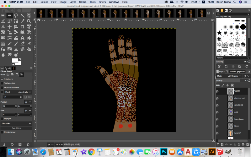
Now we are done. Save it in .XCF if you want to work onn it later and edit it. Or you can export it in desired format by:
File > Export As.
"Happy Gimping!"
Blending With Illustrator
I previously worked with illustrator, but I never explored it in its true sense except tracing sketches.
I wanted to get better at it so i decided to explore more in it.
I reffered various tutorials to use illustratior in different way.
Getting Started
Tools
Blend
Pucker and Bloat
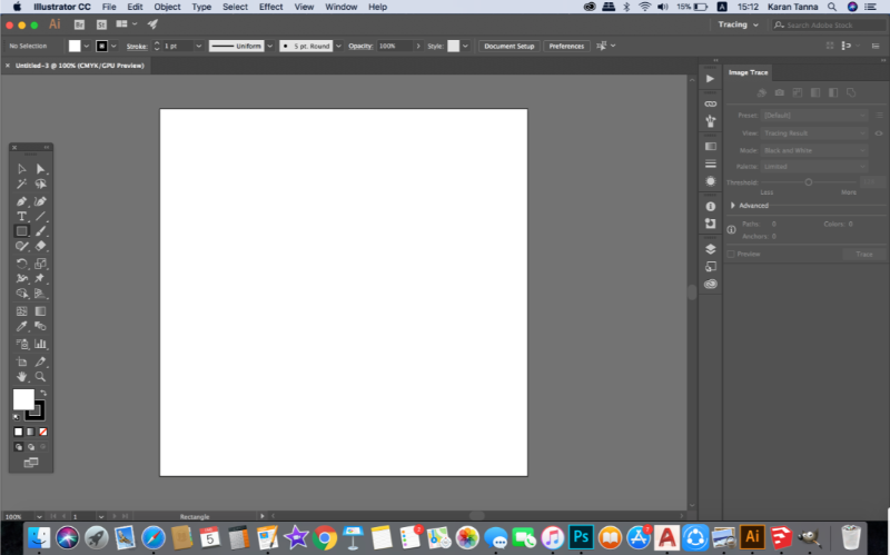
When you open illistrator it looks like above.
(Adobe UIs are great and user friendly.)To get started I made a new file from pop up box with settinngs below.
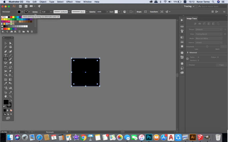
Now use rectangle tool and cover the canvas with it. Fill it black. Lock the layer by Command + 2.
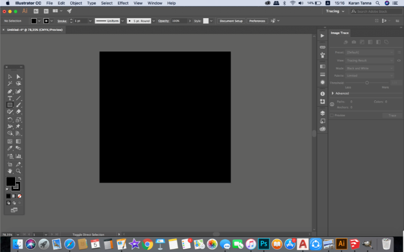
But before moving on check this settings otherwise your computer will hang up.
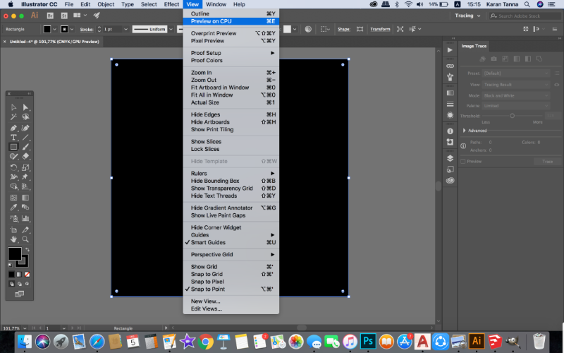
View > CPU preview. Turn it on.
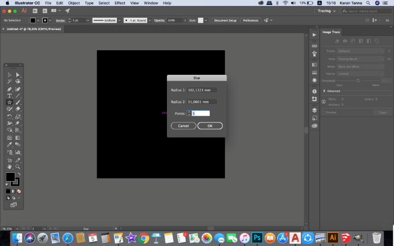
Now use star tool. The dilogue box will appear. Set it according to your preference.
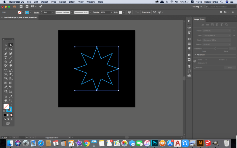
Now use direct selection tool. Drag the point, all the corners will turn into curves.
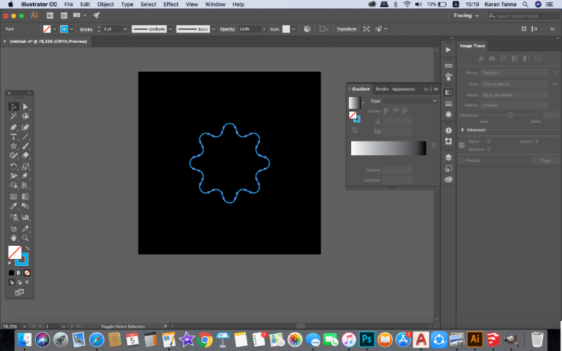
Now use gradient tool on the right and set gradients and color style on all shapes.
You can refer adobe color swatches and select colours.
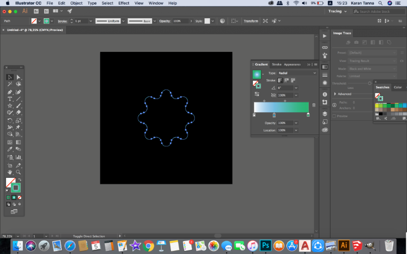
Make shapes co-inciding or any other shape as example given below and gradient them.
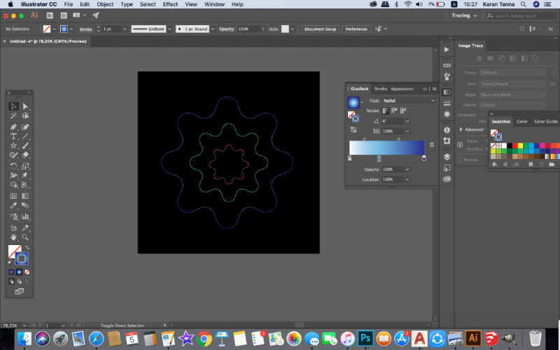
Now select the all the shapes and then go to
Object > Blend > Blend Options
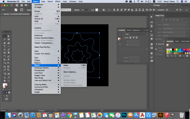
Specify numbers of step.
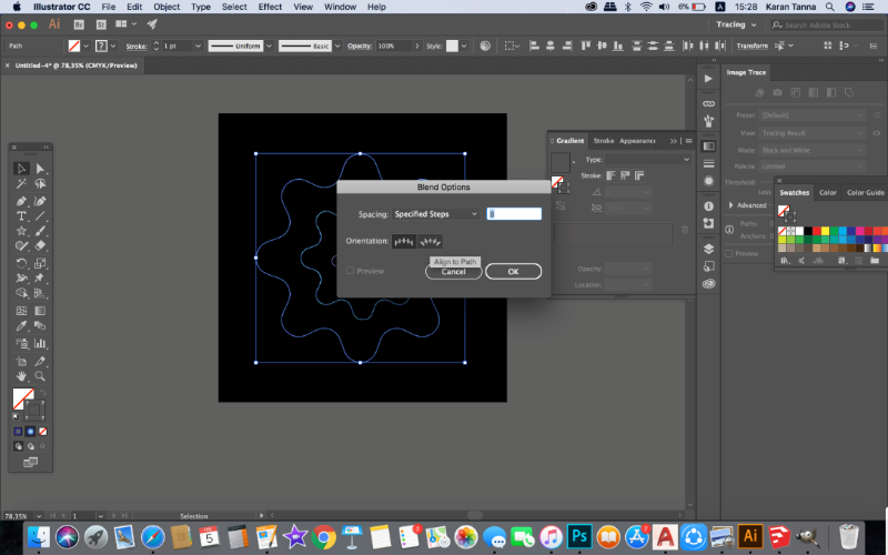
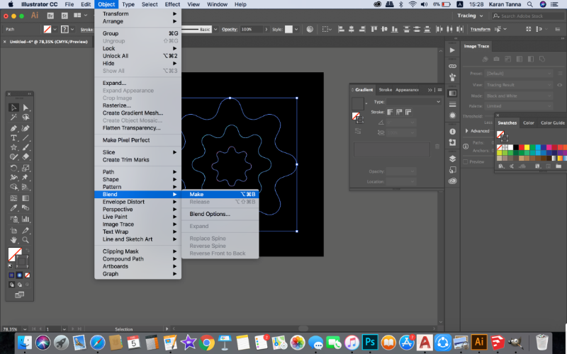
Object > Blend > Make
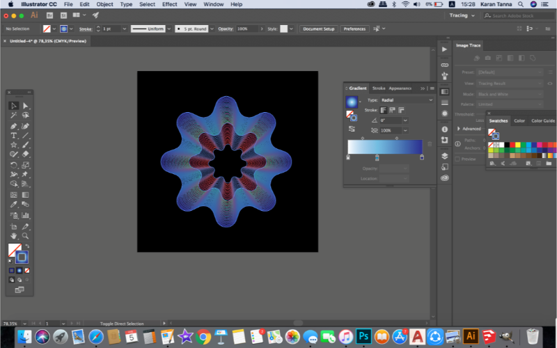
It will appear as above.
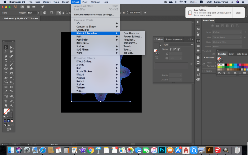
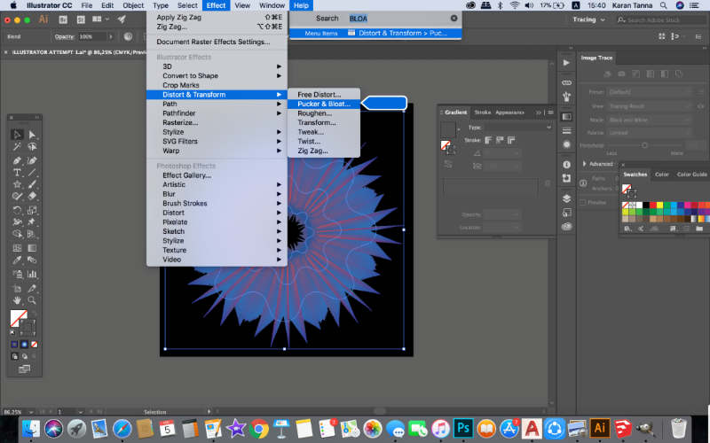
Now select it and Effect > Distort and Transform > Plucker and Boat
Then use, Zigzag tool.
Effect > Distort and Transform > Zigzag
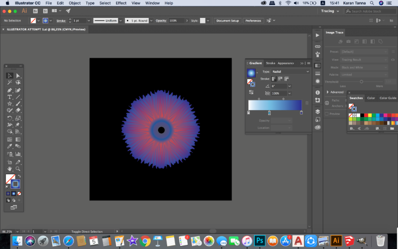
Modify the parameters and you’ll get different generations. Here is output of few more attemps.
Modelling Using Blender
I have used Sketchup and AutoCad 3D and Rhino for modelling before.
This was opportinuity where I could try my hands on new software. I was keen on trying Blender.
I reffered and various tutorials on blender.
Getting Started
Modellinng With Blender
Parametric Modelling and Blender
I wanted to make 3D model of rigid support for hand for my Final Project, thus I tried out how to make
I hardly found any souces. There were only couple of tutorials on that.
I followed above tutorials step by step and got the form of hand as below.
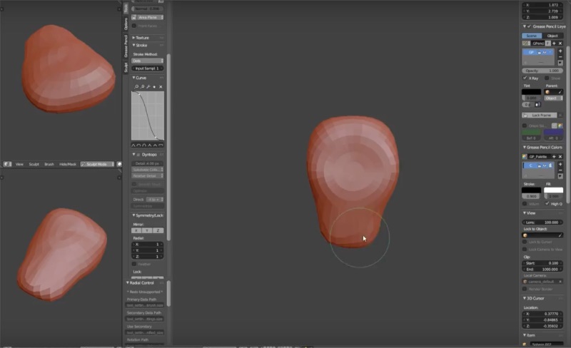
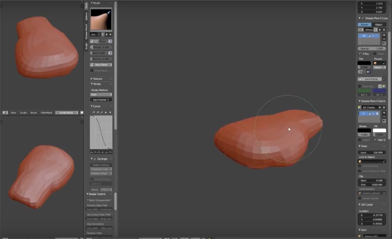
The only way I could make the model was to sculpt it. On bottom panel you'll find Scultpting Mode and then all the relevennt tools will appear.
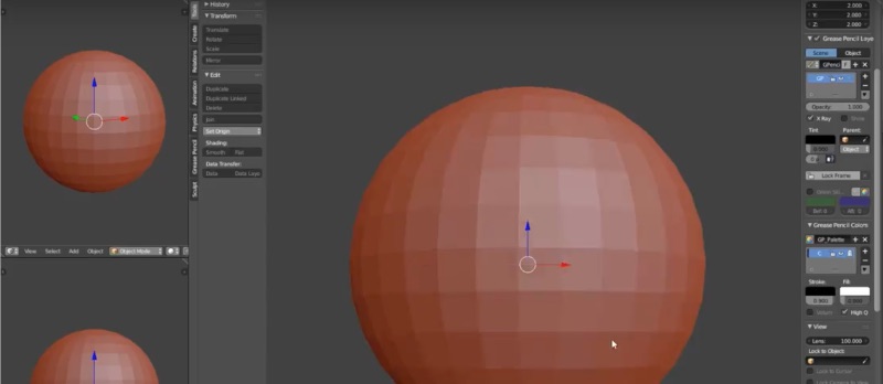
Step 1: I wanted to just make palm and not fingers,thus I started with relevant shape which is easy to sculpt is Sphere.
Choose sphere from shapes panel.
Using various brushes I sculpted the hand as steps shown in screenshot below.
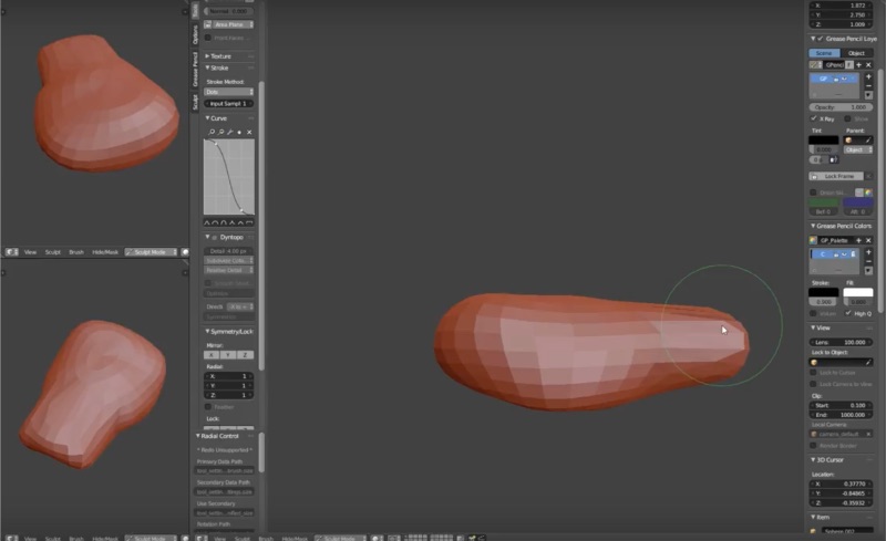
Then I pinched and flattened a bit.
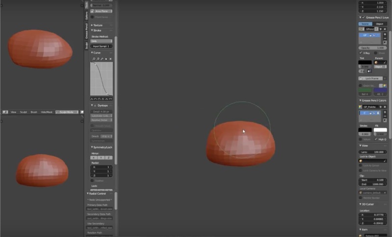
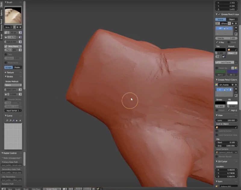
Then I stretched it and tried to make it look like palm.
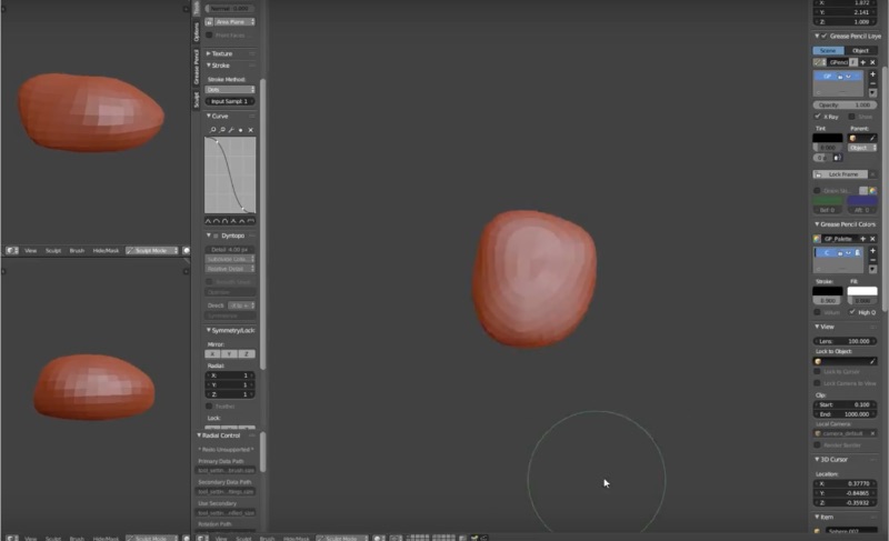
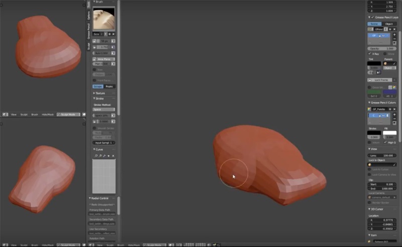
Then I sculpted more to tone it.
Then I further detailed shape.
I flattened it more to further extend it.
I sculpted more to tone it.
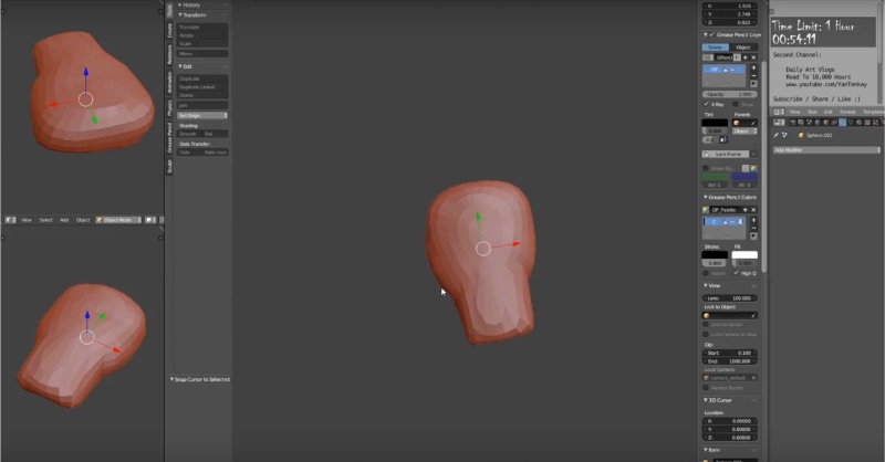
Same way I put efforts to make it look similar like palm.
Then with smoother brush I smoothen it.
You can download the model that I tried from download link below or see the embeded model.
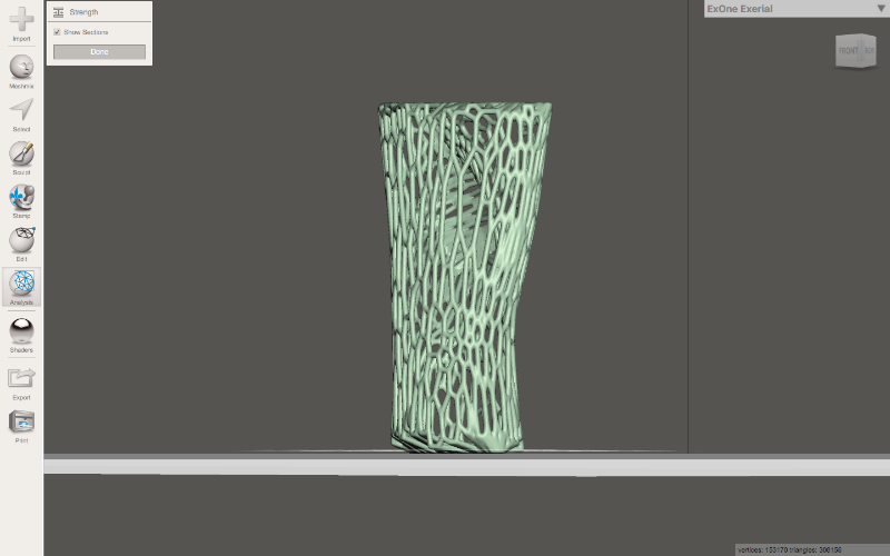
After that I opened the Meshmixer and generated frame and stimulated it for the force and strength as above.
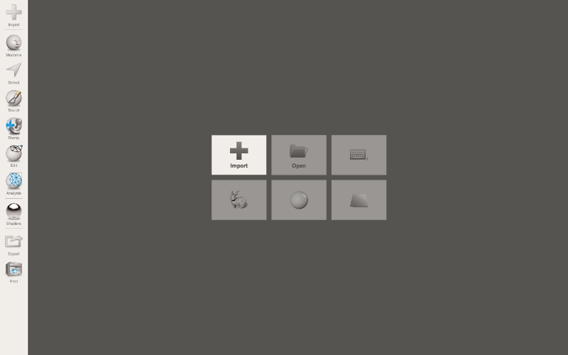
Then Import file.

Then Select.
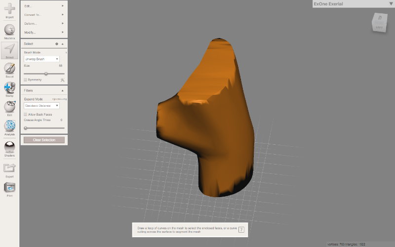
Go to edit mesh.
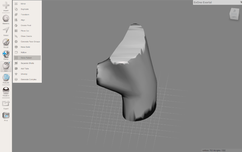
Apply parameters as below. You can optimize according to how you want it.
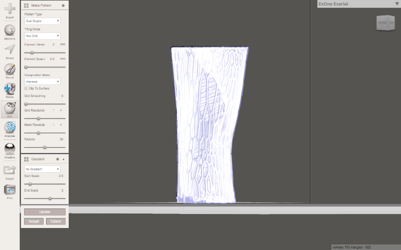
Generate Mesh.
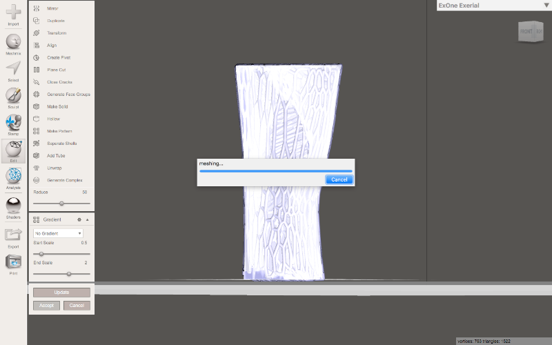
Analyse Forces and Strenth.
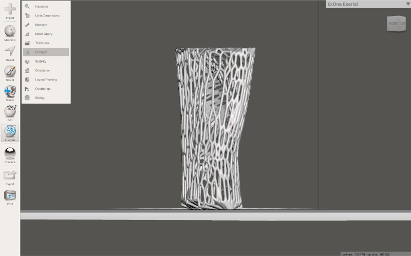
You can find final embeded model below.
What Did I Learn?
This week was interesting. In 2D design, I learned the detail difference between Raster and Vector.
I also learned how to efficiently use tools and work in layers. I found out that it is really important to know which tool to use where.
I had misconception that with vector you can't produce rendered realistic images. With blend tool you can produce really high quality vector image. Ofcourse blend tool reuires faster GPU/CPU to perform more number of steps.
In 3D, I found it challenging to make hand with parameters, as I wanted. Thus I used direct modelling technique. I will use parametric design tools as I learn more in cominng weeks ie. Computer Controlled Cutting, Molding Castinng, etc.