Week 6 : 3D Scanning and Printing
This week is about another important process. 3D printing and scanning. We saw the different types of scanning processes and methods along with the post-processing of the same.
This week is about another important process. 3D printing and scanning. We saw the different types of scanning processes and methods along with the post-processing of the same.
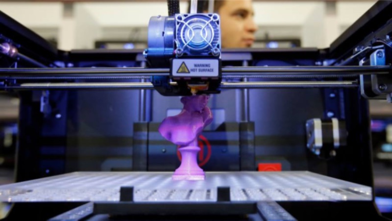
3D printing or additive manufacturing is a process of making three dimensional solid objects from a digital file. The creation of a 3D printed object is achieved using additive processes. In an additive process an object is created by laying down successive layers of material until the object is created. Each of these layers can be seen as a thinly sliced horizontal cross-section of the eventual object.
3D printing is the opposite of subtractive manufacturing which is cutting out / hollowing out a piece of metal or plastic with for instance a milling machine.
3D printing enables you to produce complex (functional) shapes using less material than traditional manufacturing methods.
In the history of manufacturing, subtractive methods have often come first. The province of machining (generating exact shapes with high precision) was generally a subtractive affair, from filing and turning through milling and grinding.
Additive manufacturing’s earliest applications have been on the toolroom end of the manufacturing spectrum. For example, rapid prototyping was one of the earliest additive variants and its mission was to reduce the lead time and cost of developing prototypes of new parts and devices, which was earlier only done with subtractive toolroom methods (typically slowly and expensively). However, as the years go by and technology continually advances, additive methods are moving ever further into the production end of manufacturing. Parts that formerly were the sole province of subtractive methods can now in some cases be made more profitably via additive ones.
However, the real integration of the newer additive technologies into commercial production is essentially a matter of complementing subtractive methods rather than displacing them entirely. Predictions for the future of commercial manufacturing, starting from today’s already- begun infancy period, are that manufacturing firms will need to be flexible, ever-improving users of all available technologies in order to remain competitive.
This week I also watched a documetary on 3D printing suggested by Neil during class. Print the Legend is a 2014 documentary film and Netflix Original focused on the 3D printing revolution. It delves into the growth of the 3D printing industry, with focus on startup companies MakerBot and Formlabs, established companies Stratasys, PrintForm and 3D Systems, and figures of controversy in the industry such as Cody Wilson.
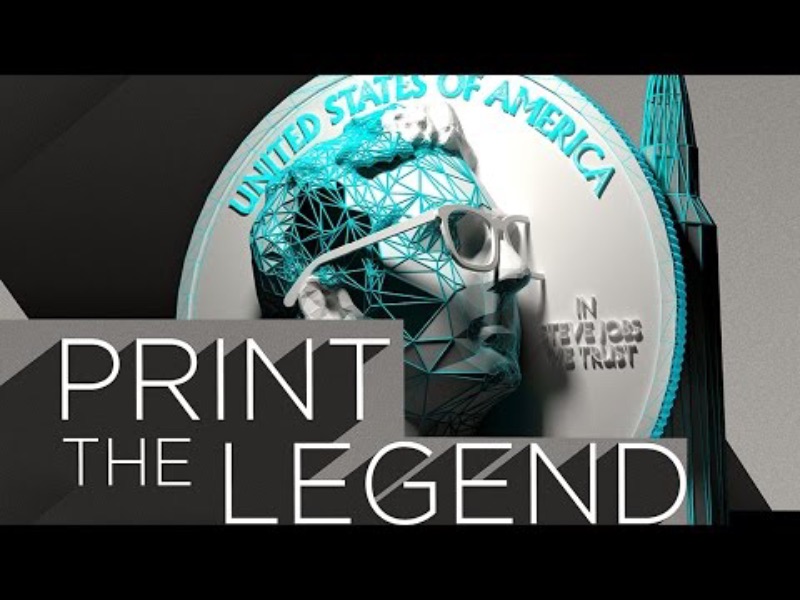
To watch the film on Netflix click below.
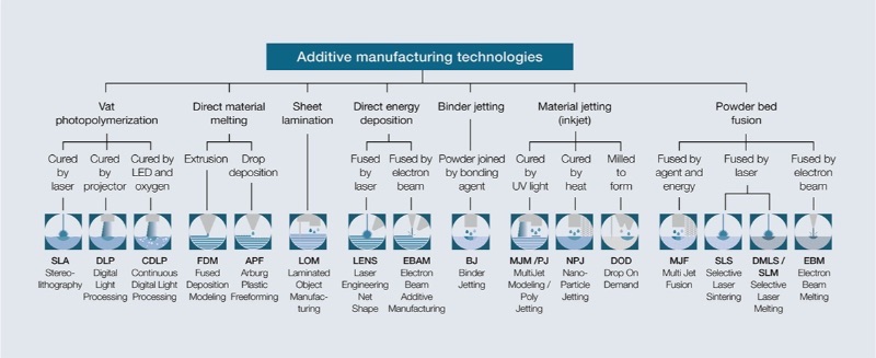
There are several ways to 3D print. All these technologies are additive, differing mainly in the way layers are build to create an object. Some methods use melting or softening material to extrude layers. Others cure a photo-reactive resin with a UV laser (or another similar light source) layer by layer. To be more precise: since 2010, the American Society for Testing and Materials (ASTM) group “ASTM F42 – Additive Manufacturing”, developed a set of standards that classify the Additive Manufacturing processes into 7 categories according to Standard Terminology for Additive Manufacturing Technologies.
These seven processes are:
Applications include rapid prototyping, architectural scale models & maquettes, 3D printed prosthetics and movie props. Other examples of 3D printing would include reconstructing fossils in paleontology, replicating ancient artifacts in archaeology, reconstructing bones and body parts in forensic pathology and reconstructing heavily damaged evidence acquired from crime scene investigations.
The worldwide 3D printing industry is expected to grow from $3.07B in revenue in 2013 to $12.8B by 2018, and exceed $21B in worldwide revenue by 2020. As it evolves, 3D printing technology is destined to transform almost every major industry and change the way we live, work, and play in the future. Source : Wohlers Report 2015
The 3D printing industry encompasses many forms of technologies and materials. When most people think of 3D printing they vizualize a simple desktop 3D printer but that’s just the tip of the iceberg. 3D printing can be divided into metal, fabrics, bio and a whole host of other industries. For this reason, it’s important to see it as a cluster of diverse industries with a myriad of different applications.
In the first half of 2017, Sculpteo’s state of 3D printing reported its uses in industrial sectors as:
Consumer Goods (17%)
Industrial Goods (17%)
High Tech (13%)
Services (9%)
Healthcare sectors (7%)
In the third quarter of 2017, Materialise reported increased revenues for their software, medical and manufacturing divisions. The revenue amounted to a $6 million increase in total when compared to the previous year. This is indicative of those very same increasing applications within the industry as the field grows larger.
3D printing is becoming more and more intertwined with the day-to-day operations of businesses. In terms of outlook, CEOs definitely see 3D printing as a benefit. Most expect a 72% rise in spending for 2018 and 55% expect one in 2017. At this stage, most companies are primarily focusing on research and development and prototyping.
FFF / FDM 3D printers are the most used 3D printers as of 2018 with SLS coming in second. Although, over the years metal printing has been climbing. This is to be expected since there is massive amounts of R and D being put into the metal side of additive manufacturing. Company’s like Google and General Electric have been investing in various technologies over the course of the year, possibly having seen the future potential of metal printing.
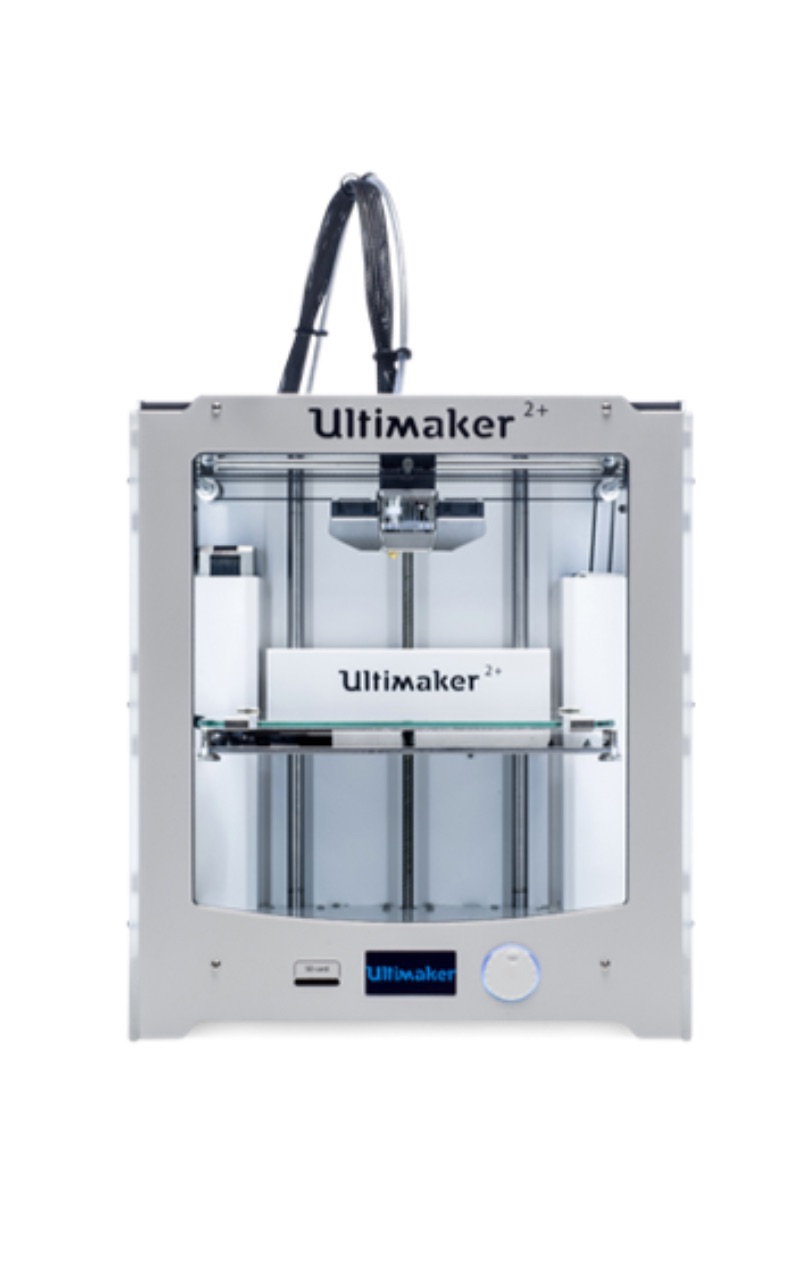
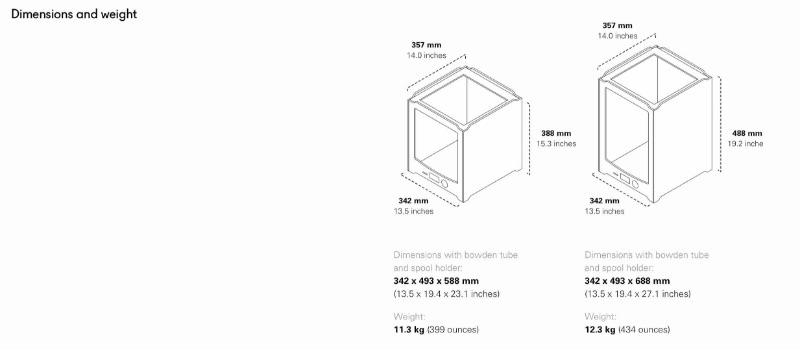
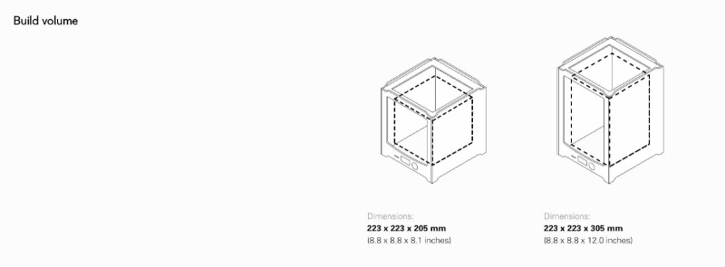
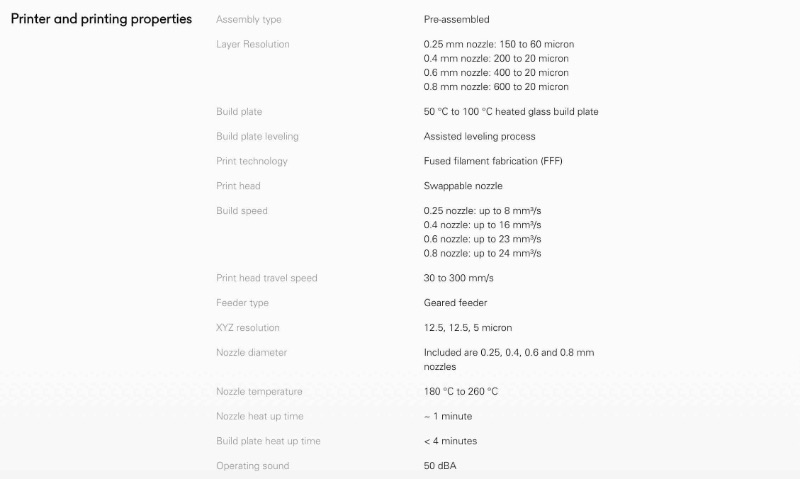
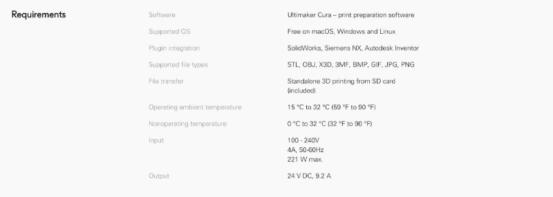
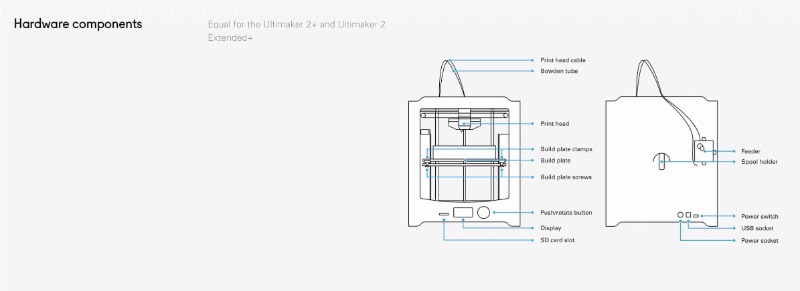
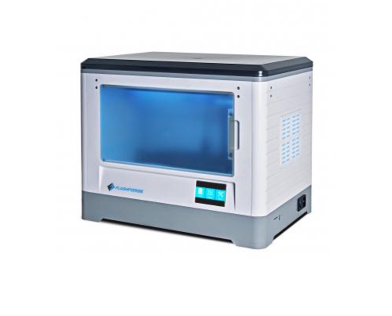
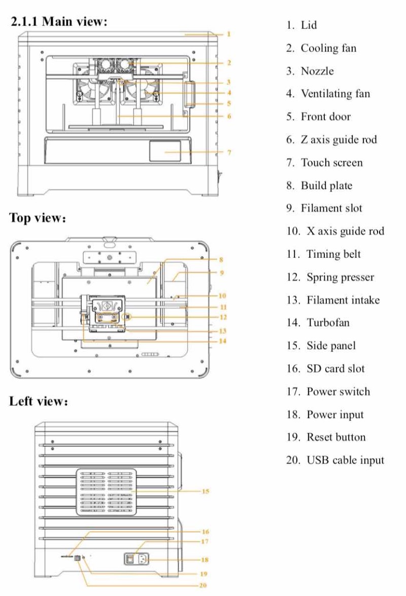
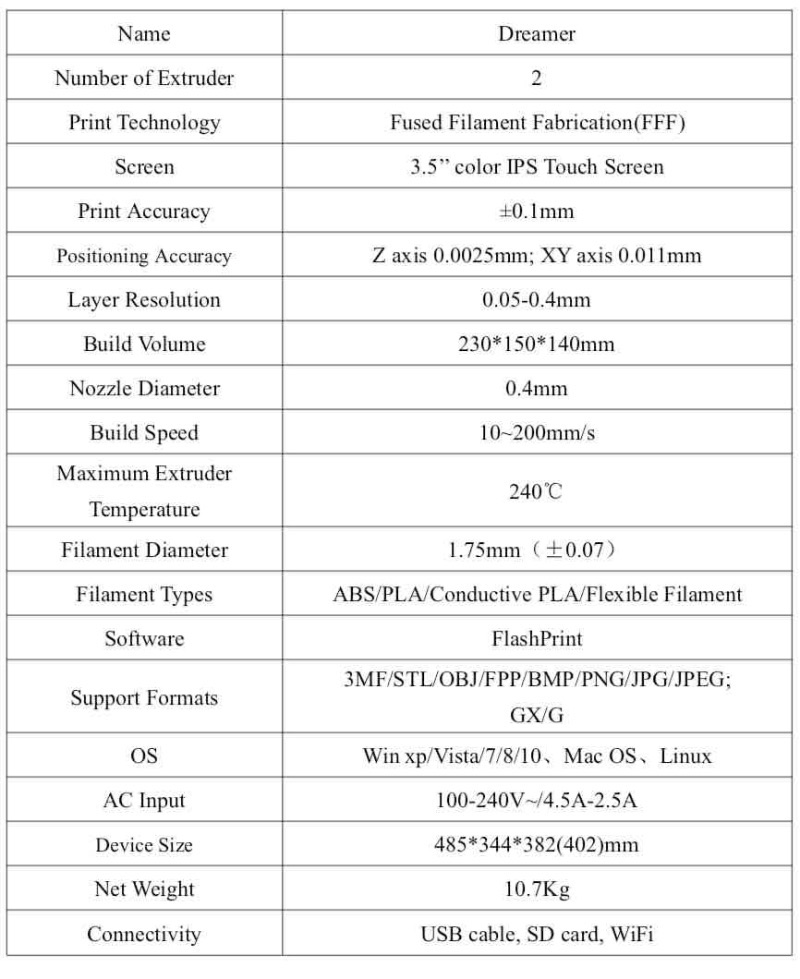
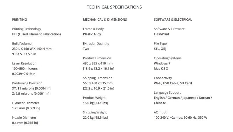
We have two 3D Printer at the lab. I have used previosly Ultimaker 2+ with slicing software Cura for 3D printing. This time I have used Flashforged Dreamer with FlashPrint as slicing tool. The specs for the machines are as given below :

Slicing softwares are used to generate G-code (Ie. Machine code). We can set various parameters in it like Infill, Print Speed, etc.. Below are slicing software that we use at our lab.
Ultimaker Cura
Cura is an open source 3D printer slicing application. It was created by David Braam who was later employed by Ultimaker, a 3D printer manufacturing company, to maintain the software.
Ultimaker Cura is used to do slicing in Ultimaker 3D printers. This is the native software for slicing in Ultimaker and works best with it. It generate .gcode file.
FlashForge Flash Print
FlashPrint is used as native slicing software fo FlashForge printers. And it generates .gx file. This allows less control over the print as compared to Cura. But It is easy and fast.
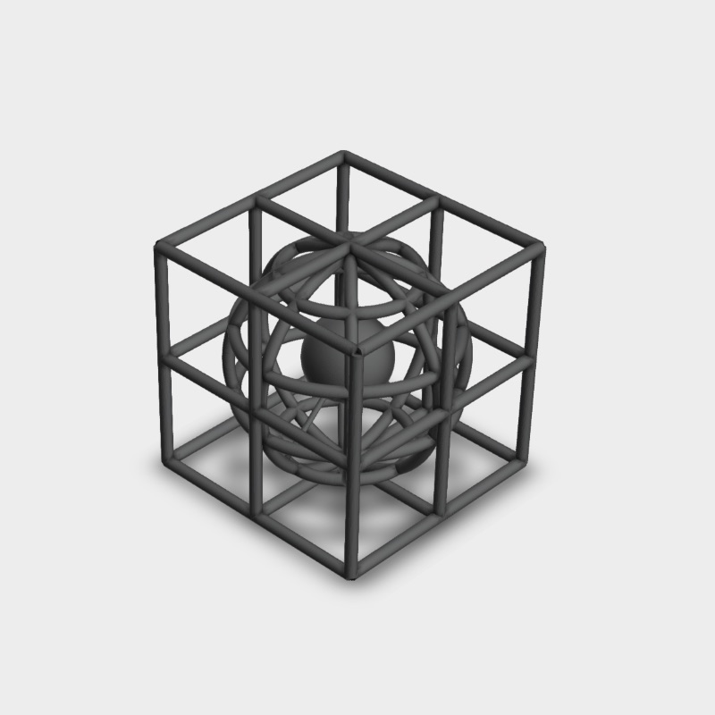
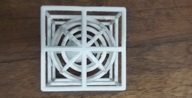
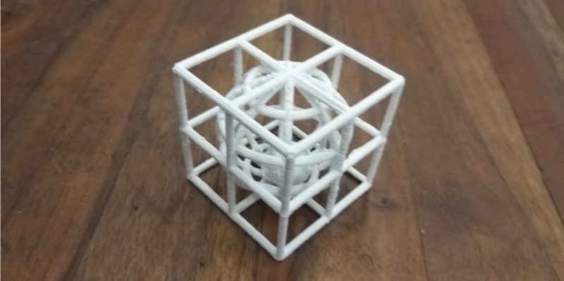
I have tried to print two objects this week. One being the hand glove that I made in Week 3. And Other is as below.
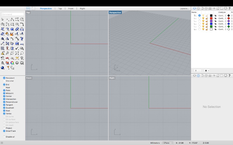
Step 1 : Open Rhino.
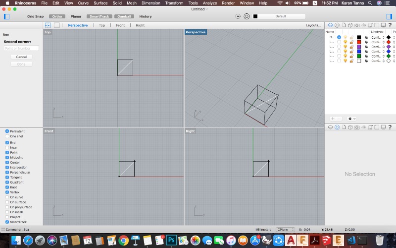
Step 2 : Make a cube of desired size.
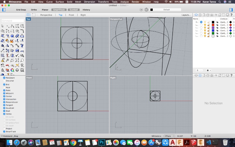
Step 3 : Then make sphere inscribing the cube and smaller sphere in the middle of sphere.
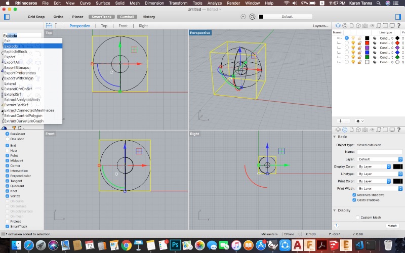
Step 4 : Now as you can see the cube lacks mesh on sides. Thus now select the cube and type 'Explode' command and press enter. Now it will get mesh on each side.
Step 5 : Now select inside bigger sphere and type 'Rebuild'. Maie U-6, V-8. This way it will rebuild mesh into 6 and 8 lines.
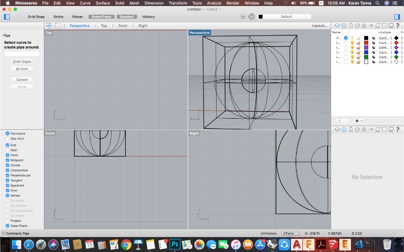
Step 6 : Now select outer cube surfaces and inner bigger sphere and type command 'Pipe' and give radius. It will appear as below. (If it doesnt appear,Go to View >Rendered.
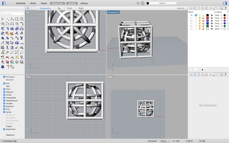
(Unfortunatly the corners didn't get fill propely. You can fix it by further exploding cube surace and extending 4 edges before doing step 6.)
Export model into .stl to further use it for slicing.
Why STL?
An STL file stores information about 3D models. This format describes only the surface geometry of a three-dimensional object without any representation of color, texture or other common model attributes. And it is common for most platforms. The main purpose of the STL file format is to encode the surface geometry of a 3D object. It encodes this information using a simple concept called “tessellation”.
What STL stands for?
It’s widely known to be an abbreviation of the word STereoLithography, though sometimes it is also referred to as “Standard Triangle Language” or “Standard Tessellation Language”.
Why 3D Printing?
Above design can't be produced seamlessly with Subtractive manufacturing. It is impossible to make it in single unit except 3D Printing. It contains hollow volumes and solid volumes inside.
Step 1 : Open FlashPrint.
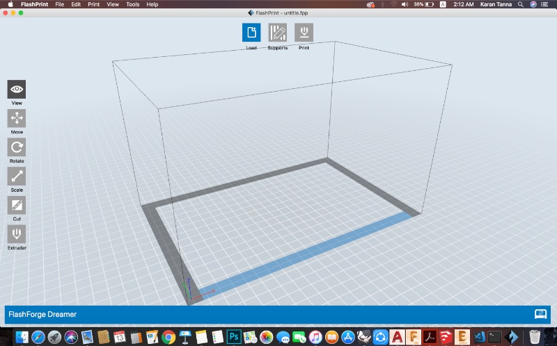
Step 2 : Load File/ Drag and Drop .stl file.
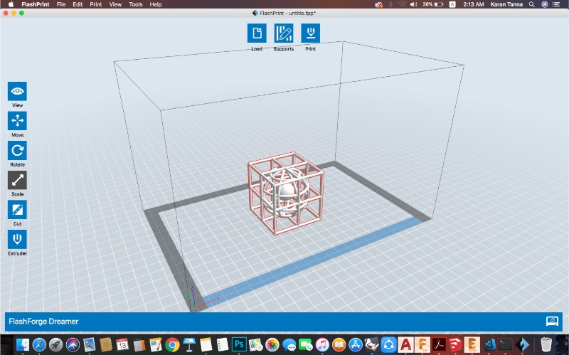
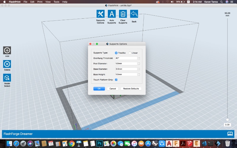
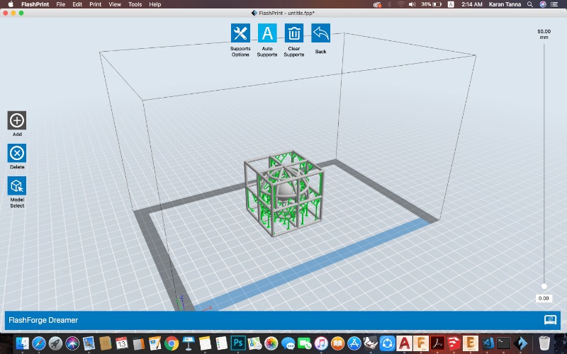
Step 3 : Go Supports. And Set Support Parameters.(If Needed)
| Parameter | Value | Description |
| Support Type | Treelike | Treelike- is more optimised and takes less time. while linear may take more time. |
| Post Diameter | 1mm | This denotes diameter of support pillar(post). |
| Base Diameter | 3mm | Diameter of pillar base. |
| Base Height | 1mm | Height of base of pillar. |
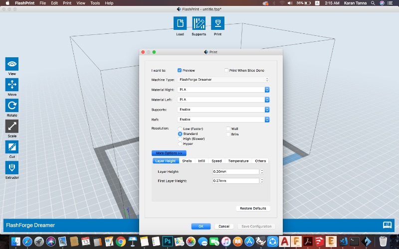
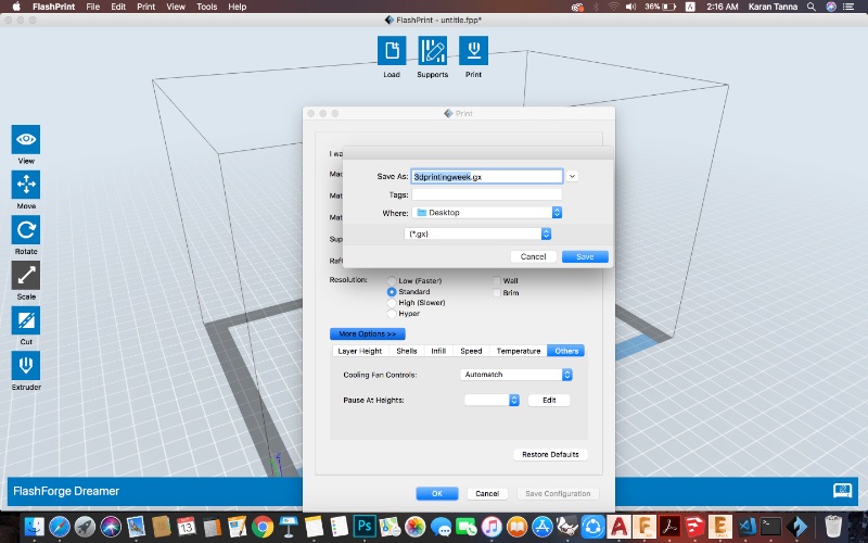
Step 4 : Then Go to print option.
Step 5 : Set Print Parameters as required.
| Parameter | Value | Description |
| Machine Type | FlashForge Dreamer | Machine Name (Printer) |
| Material Right, Left | PLA, PLA | We have two extruder printer thus left and right extruder. |
| Support | Enable | Enable/Disable support. |
| Raft | Enable | Base layer - 0 layer. |
| Resolution | Standard | Print Reslution. Higher the better. But takes more time. |
| Layer Height | 0.2mm | Height of each layer.-This determines print quality. Lower the height better the print. But takes more time. |
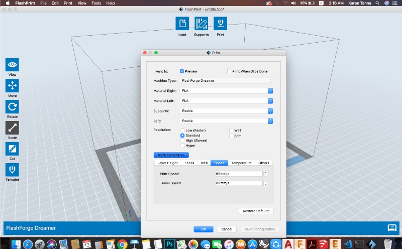
| Print Speed | 60mm/s | This determines the speed of print. More speed, less time. (Default) (Also for delicate parts run on low speeds.) |
| Travel Speed | 80mm/s | Nozzel travel speed when not printing. Keep it low when printing delicate parts. |
| Infill | 100 % | The filling percentage. Determines solidity. I have kept 100 as, I have thin pipes. Thus it would be better as it will be solid. |
Step 6 : Save .gx code. Then transfer it using SD Card or LAN to machine.
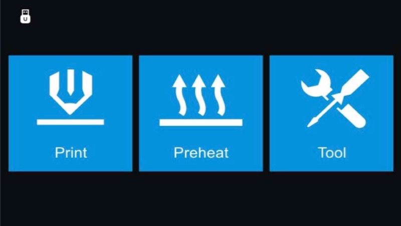
Step 7 : On Machine : Print > Select the the file > Print.
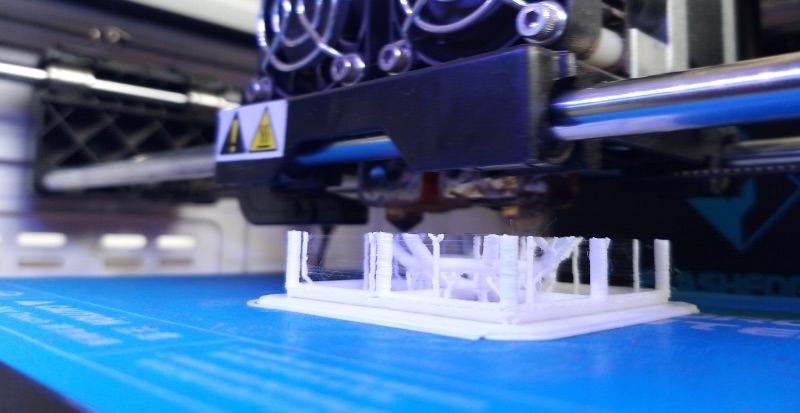
Step 8 : Watch it getting printed and after it is done remove it from bed.
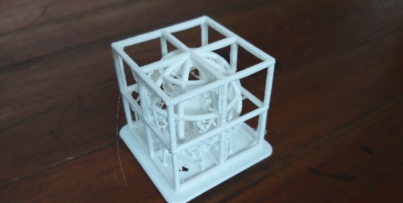
Step 9 : Remove the supports.
3D scanning is a technique used to capture the shape of an object using a 3D scanner. The result is a 3D file of the object which can be saved, edited, and even 3D printed. Many different 3D scanning technologies exist to 3D scan objects, environments, and people. Each 3D scanning technology comes with its own limitations, advantages, and costs.
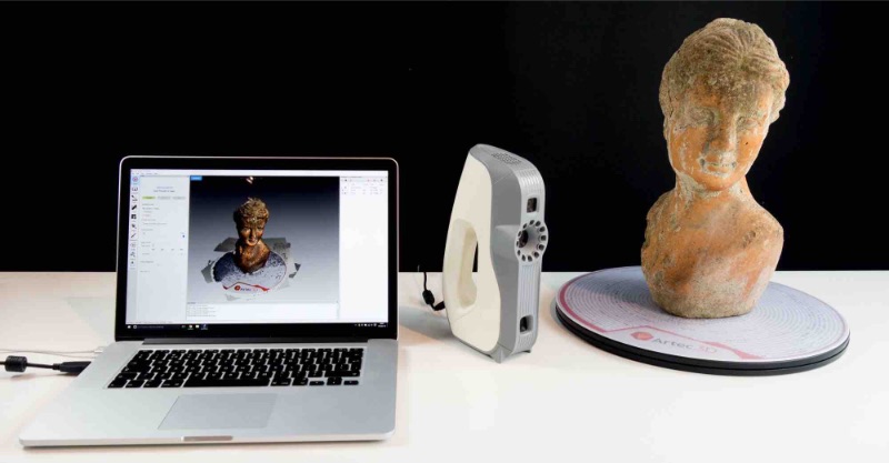
The basic principle is to use a 3D scanner to collect data about a subject. The subject can be: an object an environment (such as a room) a person (3D body scanning) Some 3D scanners can simultaneously collect shape and color data. A 3D scanned color surface is called a texture.
3D scans are compatible with Computer Aided Design (CAD) software and also 3D printing, after a little preparation on the computer software. A 3D scan can give a lot of information about the design of an object, in a process called reverse engineering.
3D scanning technologies rely on different physical principles and can be classified in categories:
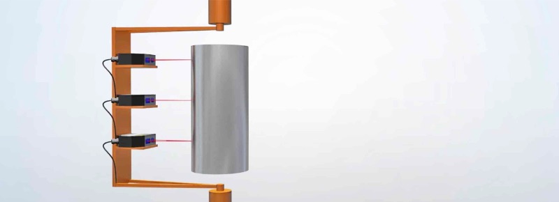
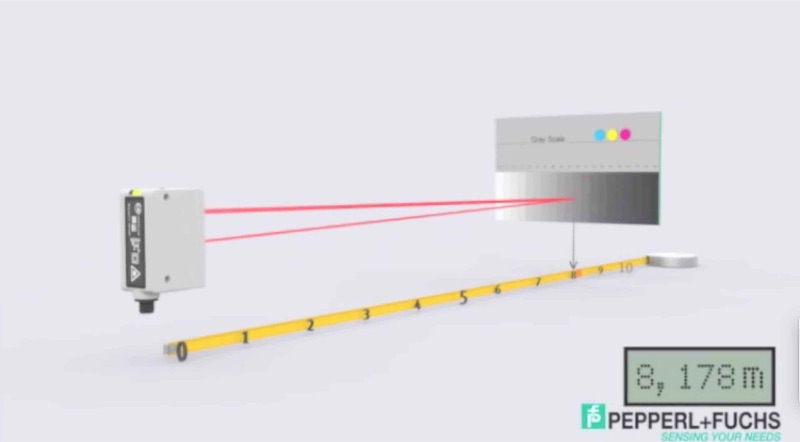
Laser Triangulation : 3D scanning technology, as illustrated on the image, projects a laser beam on a surface and measures the deformation of the laser ray.
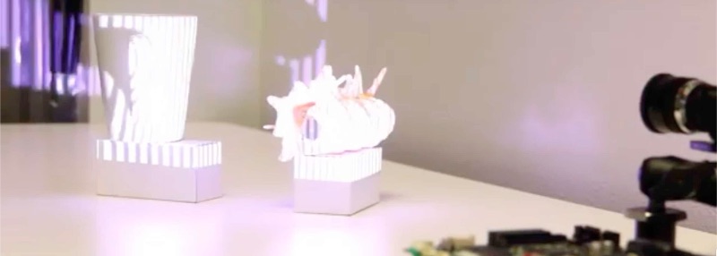
Structured light : 3D scanning technology measures the deformation of a light pattern on a surface to 3D scan the shape of the surface.
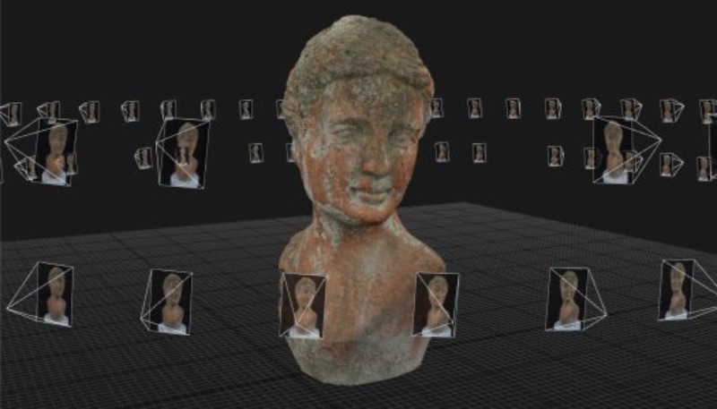
Photogrammetry : It is also called 3D scan from photographs, reconstructs in 3D a subject from 2D captures with computer vision and computational geometry algorithms.
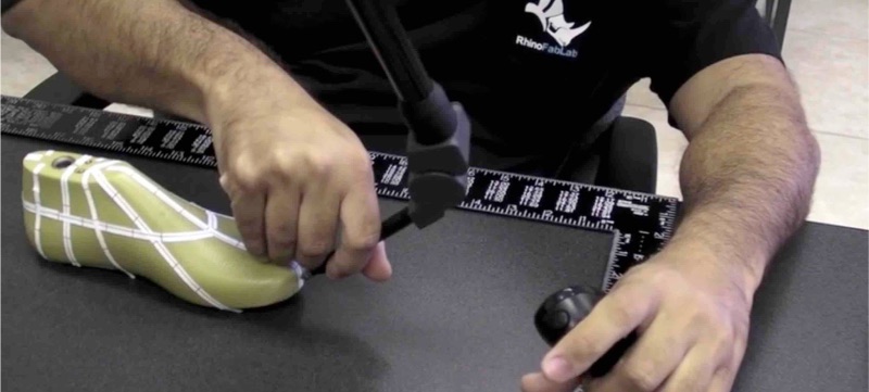
Contact-based : 3D scanning technology relies on the sampling of several points on a surface, measured by the deformation of a probe.
Laser pulse: It is also called time of flight) 3D scanning technology is based on the time of flight of a laser beam. The laser beam is projected on a surface and collected on a sensor. The time of travel of the laser between its emission and reception gives the surface’s geometrical information.
For this week I tried 3D scanning using Photogrammetry with MetaShape and with Kinect 360 as well as using SCANN3D android AR based 3D scanner.
I tried MetaShape to try photogrammetry 3D scanning process on MacOS.
It has really simple work flow you just need to follow steps on 'Workflow' on Metashape menu bar.
As you follow the workflow it will generate model accordingly.
Workflow > Add Photos > Align Photos > Build Dense Cloud > Build Mesh > Build Texture > Align Chunks > Merge Chunks and Export
(Note : Click as many as possible photos from different angles for better result.)
Step 1 : Add Photos.
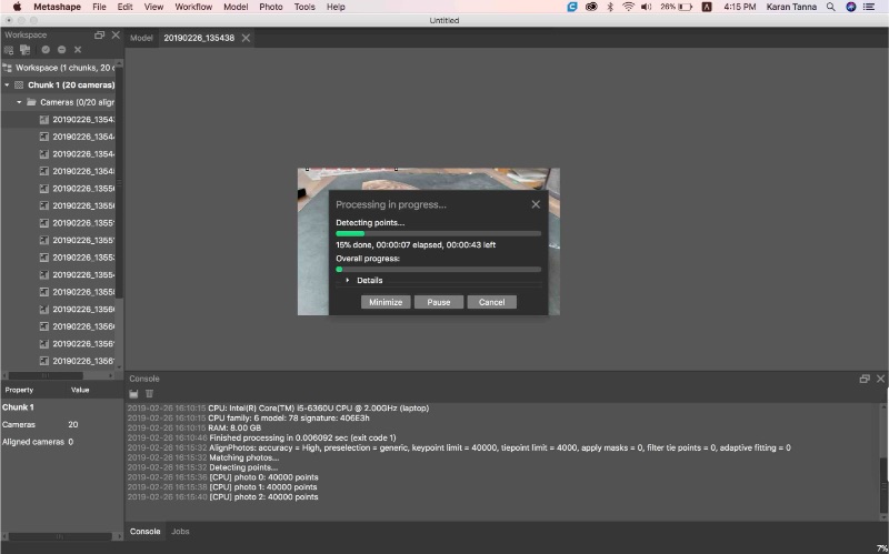
Step 2 : Align Photos.
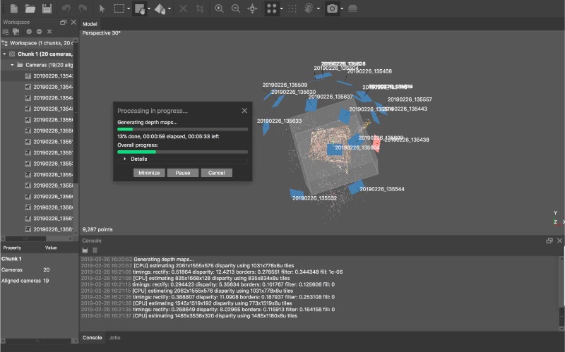
Step 3 : Build Dense Cloud.
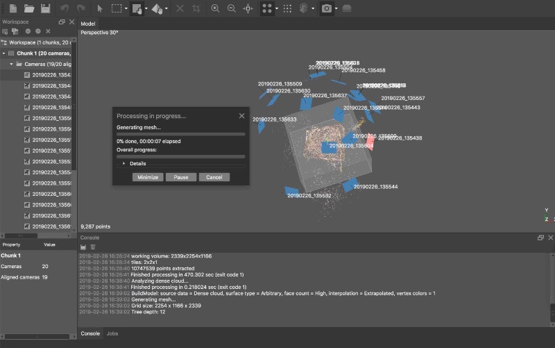
Step 4 : Build Mesh.
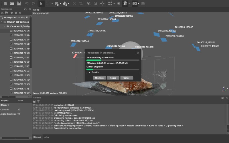
Step 5 : Build Texture.
Step 6 : Align Chunks.
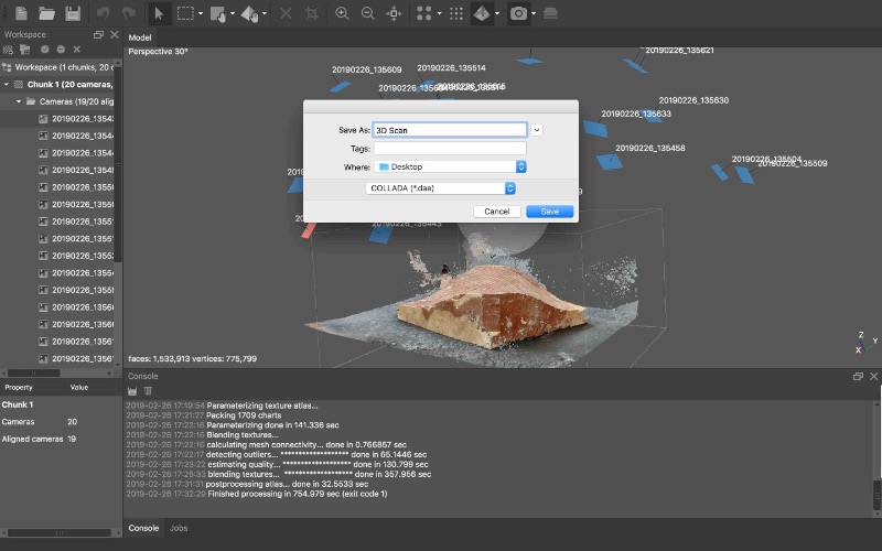
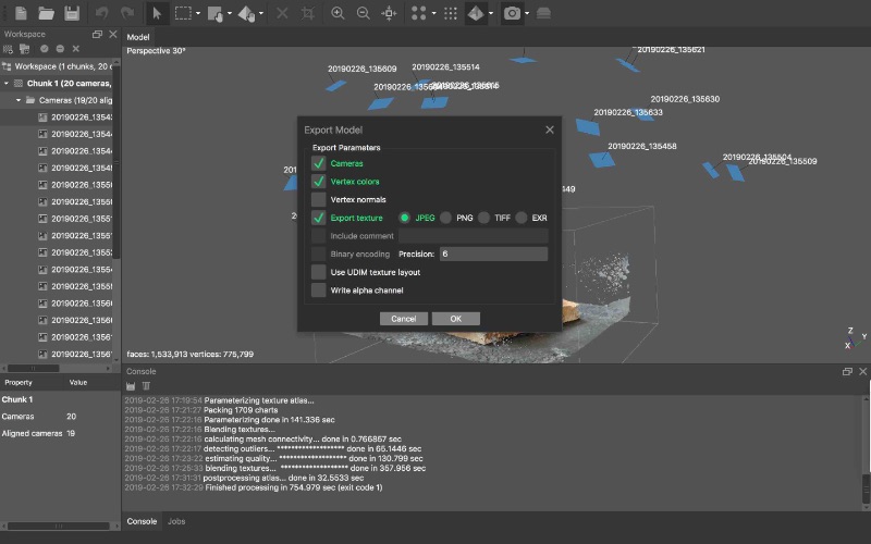
Step 7 : Merge Chunks and Export.
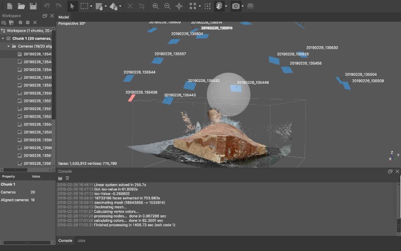
MetaShspe Output
Oberevation 1 : It scanned top layer(curve) well. It scatters pointcloud badly through pictures.
Observation 2 : It takes lot of time to build mesh at High Quality (6 hours). It takes very high config. workstation to get accurate high quality model.
This week I also used Kinect (Microsoft) to do 3D Scanning. The Skanect interface is very easy.
I scanned my friend with Skanect & Kinect.
You can download Skanect and its drivers from link below.
Step by step on how to use Skanect is given below.It works in 5 stages.
Prepare > Record > Reconstruct > Process > Share
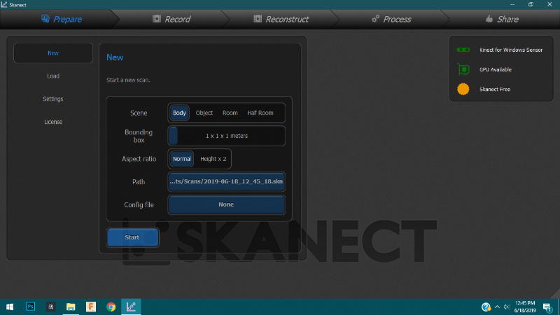
Below is the screen shot of home screen of Skanect Windows App.
Follow top bar and go through it to scan.

Prepare :
I am scanning a body. Thus I used settings for the same. The settings are as below
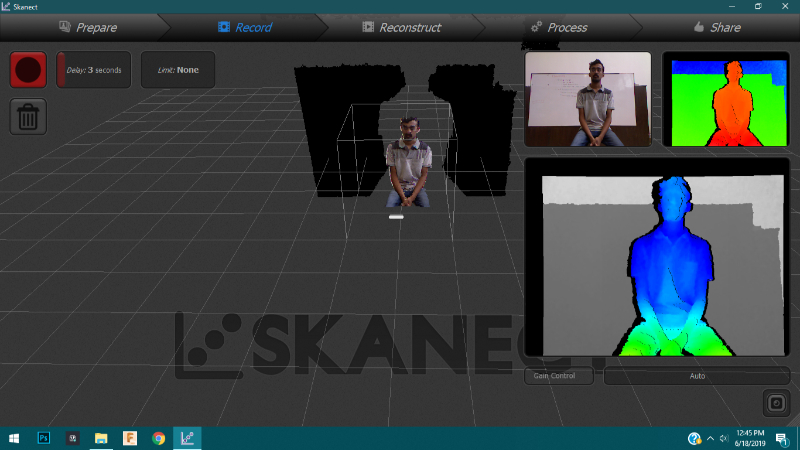
Record :
Then I asked my friend to sit and rotate very slowly in front of the Kinect Camera.
Click button on top left to start/stop recording.
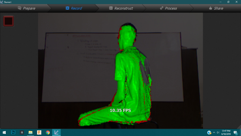
Images from the record process are as below.
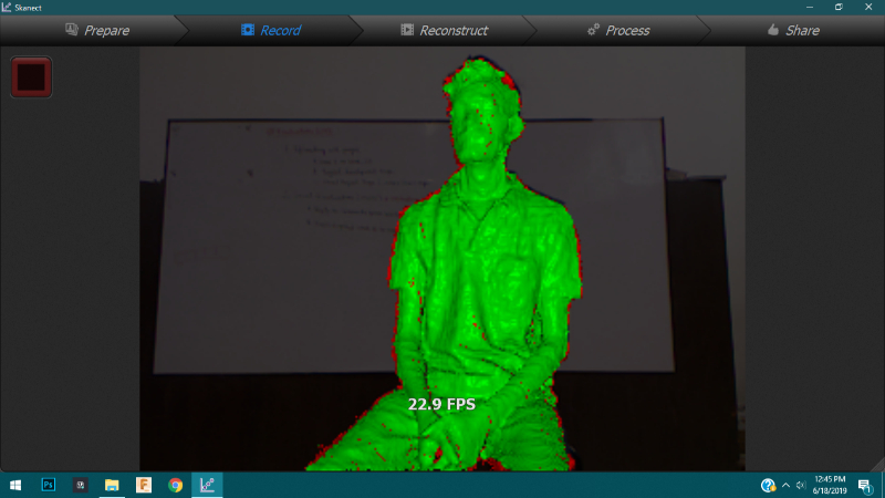
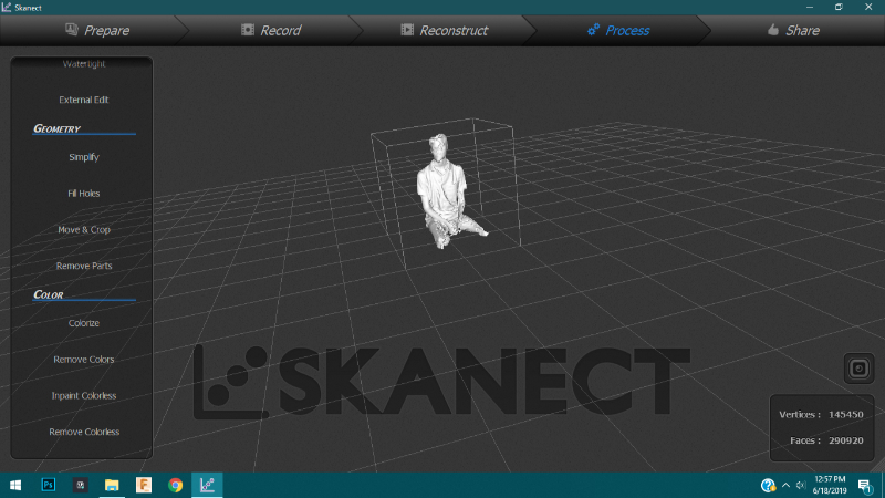
Reconstruct & Process :
The Reconstruct feature is used when the model is scattered and distorted. Then I fixed the model using Process.
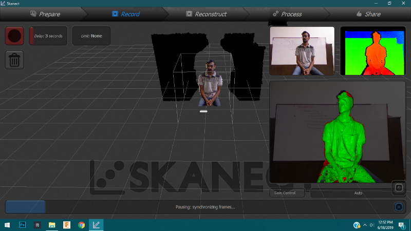
The above screenshot shows model when scanning record is done.
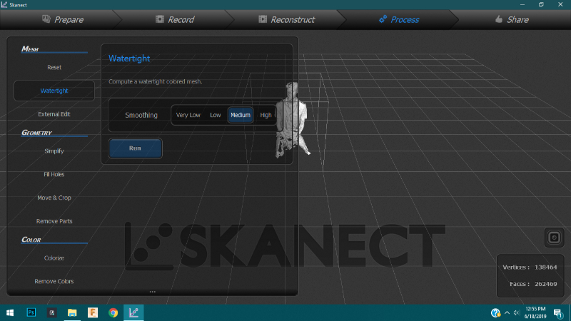
The mesh of scanned body is with gaps thus water-tight function closes all the gaps.
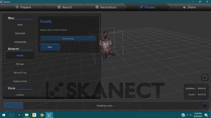
Then geometry tab is for fixing geometry. I fixed and simplify geometry to smoothen.
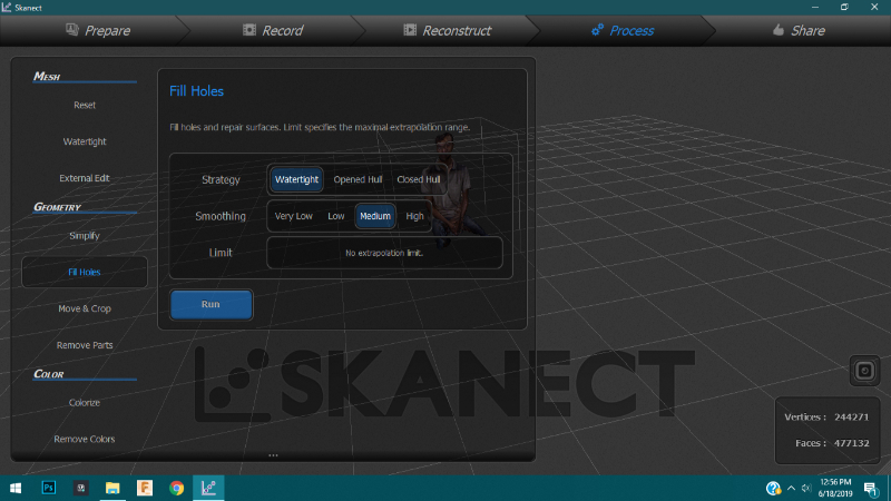
Then this Fill Holes funtion fills tiny holes in the model if it still exists (You dont really need it after using Water-tight as before.)
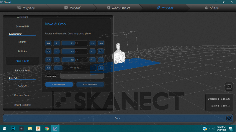
Then Move and Crop function crop the model from ground plane. You can shift the plane using 'Ty' slider.
After that I removed colours.
Share :
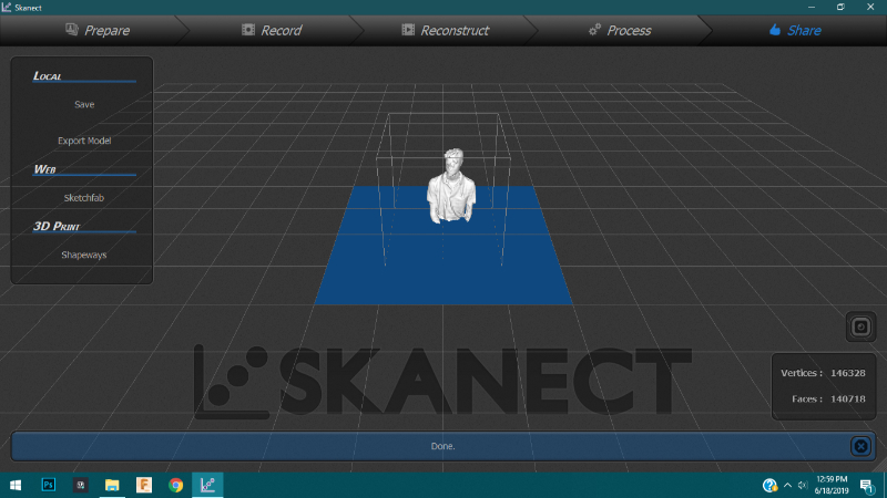
When you click the Share tab above screen will appear.
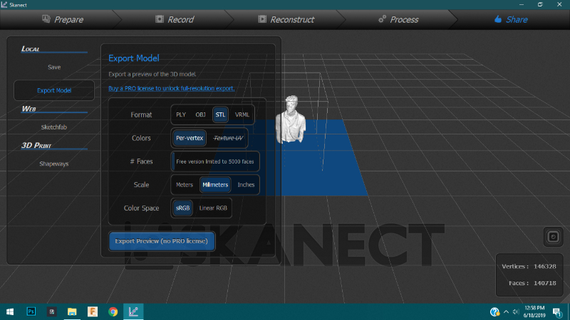
Then go to share tab and and exported in .stl format. You can save it in other formats as well according to need.
This week in 3D prinntinng I learned about different types of 3D printing methods.
During the group project as I designed file for X,Y,Z calibration. From the result found out about tolerences and movement in various axes.
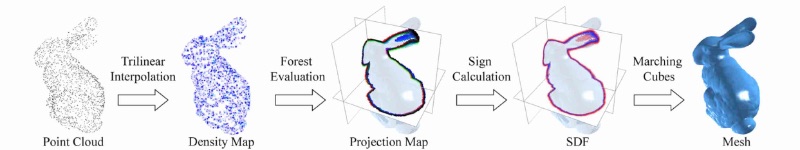
In 3D scanning I learned how to create dot map of object and then generate mesh and then textures.
This week we did various types of tolerance tests for 3D Printing. I contributed with making the file for XYZ tolerance test. I designed the test to be in mm thus we could measure the accuracy of printing in all axes. The file/ model that I made is embeded below.
For further reference refer the 'Group Assignment' button/tab at the end of page.