What is CNC?
The meaning of CNC is Computer Numerical Control. Computer numerical control (CNC) is programmed code that represents instructions for precise movements to be carried out by machines. Indirectly, this code defines how to automatically create, produce, or transform a virtual object into a real one.
Every CNC machine has two or more than two programmable direction of motion that is known as Axis. The axis of motion can be linear or rotary. Linear mean straight line and rotary means circular path. Depending on the axes, the complexity of these machines depends on. Speaking generally, how many axis this machines are makes it clear if these machines are simple or complex. These axes are required for causing motions that is necessary for starting the manufacturing process.
Why CNC Milling?
Without a CNC milling machine machine, the process of cutting metal for car parts or even aerospace components would be much riskier. With the support of computer programs, one can access and create high definition designs that are easily converted into Cartesian coordinates. This process even helps lower the costs of prototyping!
How To Choose Milling Bits?
When this question aroused in my mind I found this link very helpful.
What To Consider While Doing CNC ?
Type of Tool Used
Selecting a tool to use on a CNC machine mainly depends on the type of material being used, the type of work to be done, the quality of finish and the number of components to be run.
Since CNC milling is subtractive method. It requires various kind of tools to carve out material. The choice of Drill Bit would determine how your product will come up.
Type of Milling Bit
There are various types of bits on basis of its type of cutting legth region.
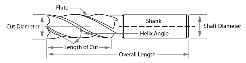
Credits: CarbideProcessors
The image above shows anatomy of a bit. The length of cut is the part which actually cuts the material, while the shank goes into the collet. Also number of flute makes difference in finishing of cut.
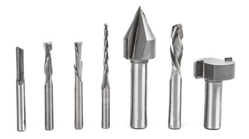
Credits : MakeMagazine
The image above shows various types of bits according to shape. You can achieve various types of cuts with each. For example you can achieve a smooth cut in curvature with triangular bit.
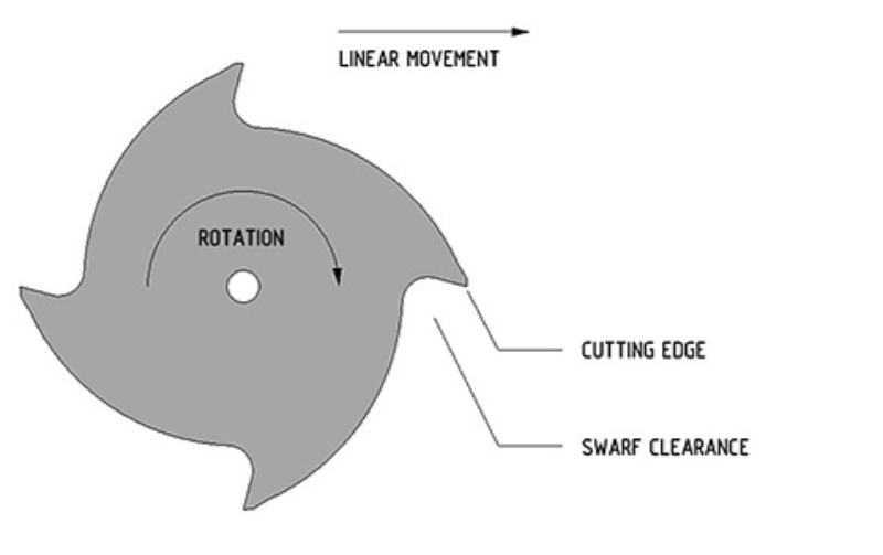
The image above shows the rotation and mechanism of moving bit.
Commonly known bits are :
1. Straight Flute
2. Endmill
3. Ballnose Mill
4. V Mill Bit
5. Compression Mill
6. T- Slot Mill
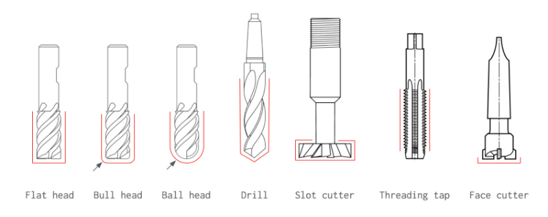
Image above shows the function and cut type of bits.
Direction of Cut
The direction of cut affects the life of a tool, the quality of the cut and the material you are working with. When selecting a tool it's important to consider the type of material you are using, the needs of the customer and the specifications of the CNC machine being used.
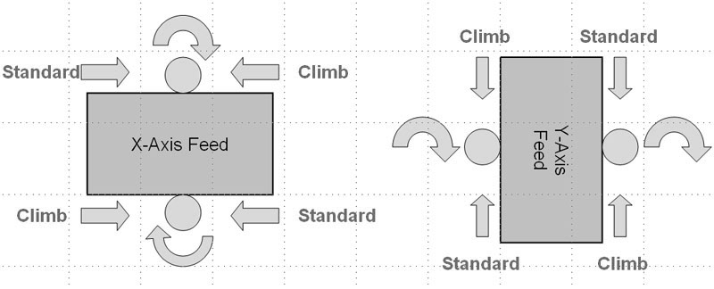
In CNC, Climb and Conventional are two direction. The diagram below shows the difference between them.
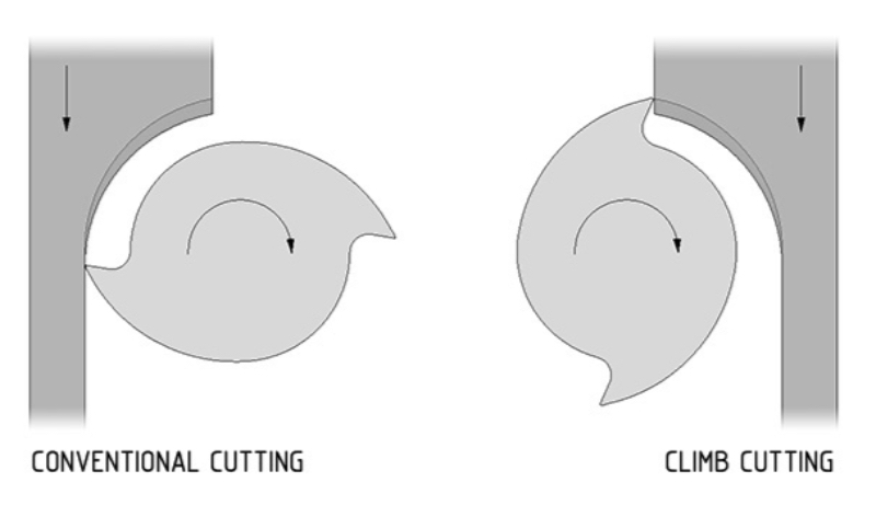
Credits : CNCcookbook
Climb Milling is generally the best way to machine parts today since it reduces the load from the cutting edge, leaves a better surface finish, and improves tool life. During Conventional Milling, the cutter tends to dig into the workpiece and may cause the part to be cut out of tolerance.
However, though Climb Milling is the preferred way to machine parts, there are times when Conventional Milling is the necessary milling style. One such example is if your machine does not counteract backlash. In this case, Conventional Milling should be implemented.
Cutting Speed
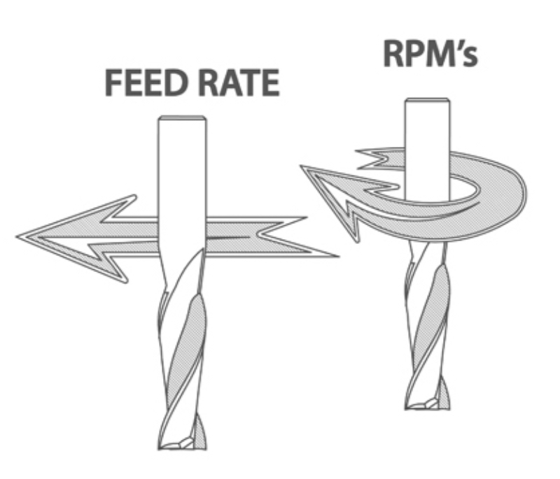
Cutting speed is based onn RPM of the tool. Meaning that with higher RPM it cuts faster at certain position than that of lower RPM.
Remember : Cutting speed is in relation to the tool itself while feed speed is in relation to the movement of the tool.
Spindle and Feed Rate
Feed speed is the rate at which the work piece moves into the cutter. It is always determined in relation to the spindle speed. Using the wrong feed speed can produce too much dust or burn the work piece. To determine the optimum feed speed you can use a feed speed table or calculate it mathematically.
Credits : WoodWorkingCanada
Out and Inside Cut
There are different type of cut types for different kinds of situation, as tool has its own thickness. Thus you need to choose what dimension you want exact and what part you want to be eliminated.
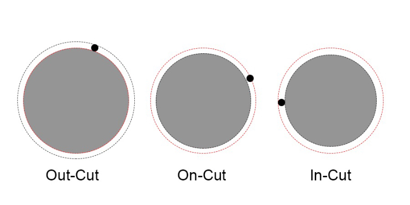
In the above image, black dot shows milling bit. In out cut the bit cuts material of ouside givfing exact dimension. Oncut reduces the material on both side and gives dimension less by (d/2; d=diamter of bit) and Incut reduces the material on inside gives dimension less by (d; d=diamter of bit)
Note: This is very crucial factor while designing the file.
Fillets
While making corners, milling tool doesn't give sharp corners thus joinery fails in the CNC product. Thus fillets are used to compensate that.
The diagram below explains T bone and Dog bone fillets.

This fillet is used in corner joints.
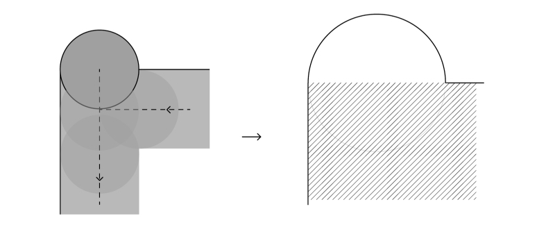
This fillet is used in one side joint./p>
Understanding The Shop Bot Machine
As part of Group work we tested various parameters.
Designing 'Something Big'
This week task was to make 'Something Big'. Here's how I did it.
Inspiration
I was very fascinated with the design of SPUN chair by Italian Furniture Company 'Magis' when I visited Magis Headquaters in 2017 situated in Italy.
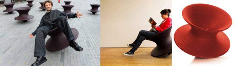
Creadits: Magis, Italy
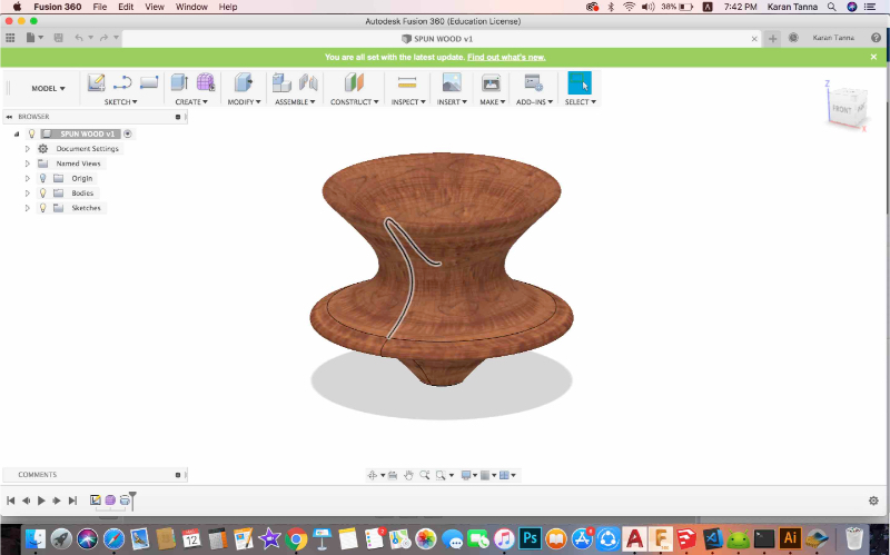
SPUN is polymer based moulded chair, ie. made with additive method. The challange was to redesign the same with CNC and with Plywood or MDF, to understand joints and forces acting on it.

Making The Prototype
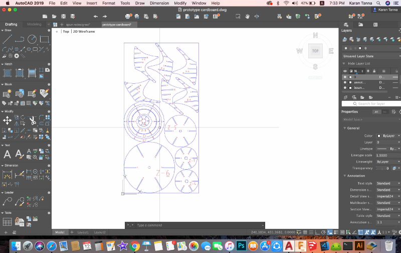
To redesign the SPUN, I started with the original product drawing.
I took image of original diagram and tried to recreate the chair using a section diagram. I started with vector drawing.
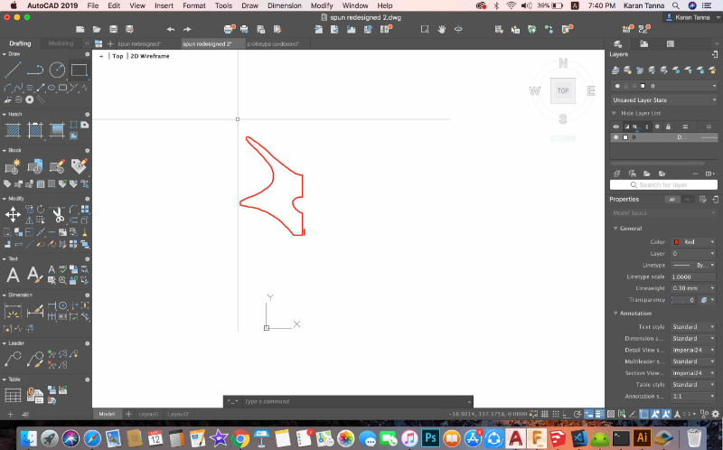
I drew the profile of the section. I modified it and make it appropriate for CNC chair. Original has slightly long and sharper corners,
I reduced that as it wont ruint the edges while touching the ground.
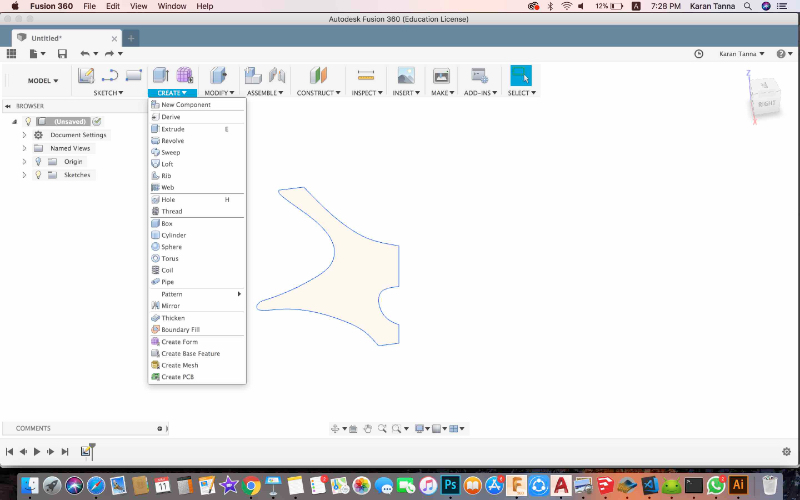
I exported it as .dxf and took it to fusion 360.
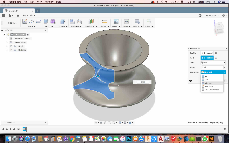
I selected the sketch and then Create > Revolve.
Since I wanted to quickly try out various alternative of parts, I used 'Slicer For Fusion 360'. After various iteration of Axes and Counts I found optimised design.
Slicer Parameters
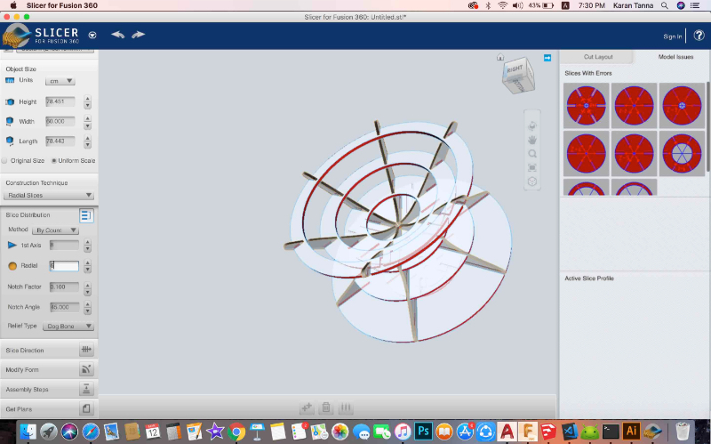
I cut it in 1:5 scale on cardboard with laser cutting machine. 6x8 slices!
I found that the last layer on top would break as span is much. Also I don't need the part touching to ground to wear and tear. Also I increased the curve slightly and and make cross section smoother
Thus for next iteration I tried to resolve that.
3D Model
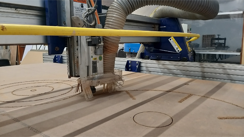
Machining With ShopBot
I used ShopBot CNC Machine for cutiing parts. Specifications of same are as given below.
Model : PRSalpha 96-48
Movement Area : 105” x 49” x 8”
Foot Print : 120” x 79” x 67”
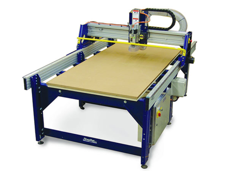
Credits : ShopBot
VOLTAGE must be specified at time of purchase. The PRSalpha requires a fused disconnect installed by a licensed electrician. Spindle may require 3 phase.
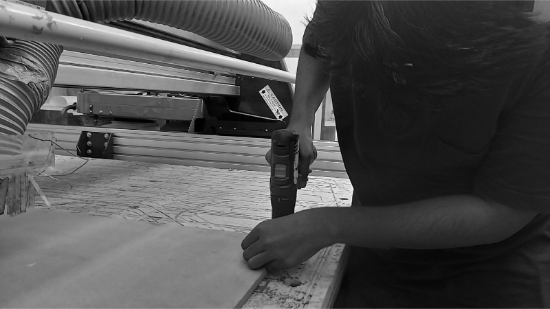
Machining Process
1. Mounting material on CNC bed.
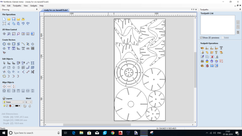
2. Generating Tool Path.
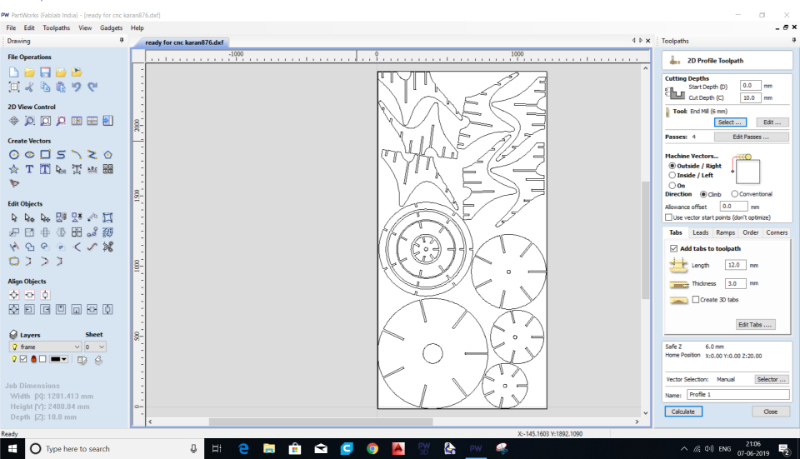
Step 1 : Import .dxf file into 'Part-works' software.
Step 2 : Select size (lngth and bredth ) during job setup ; and thickness of material. Then go to tool-path button on right side menu.
Step 3 : Following parameters menu will appear. I used following parameter to machine 10 mm MDF.
Parameter Table
Step 4 : Then select tool parameters.
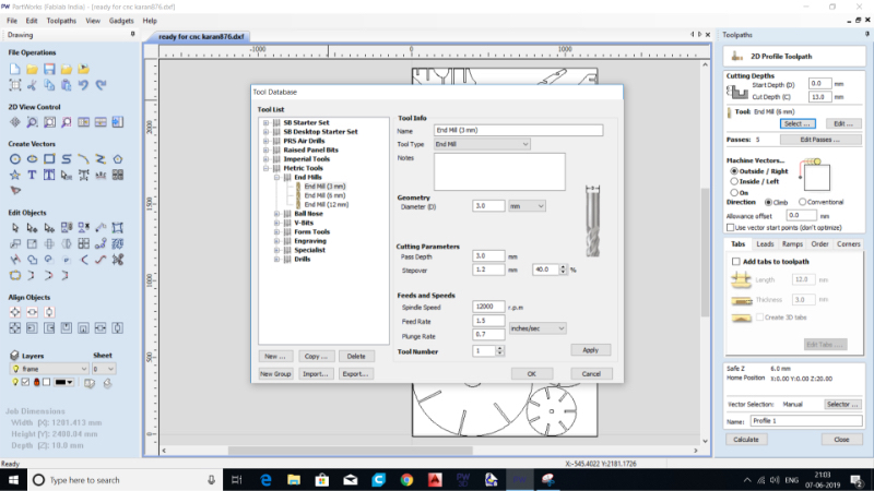
Tool Parameter Table
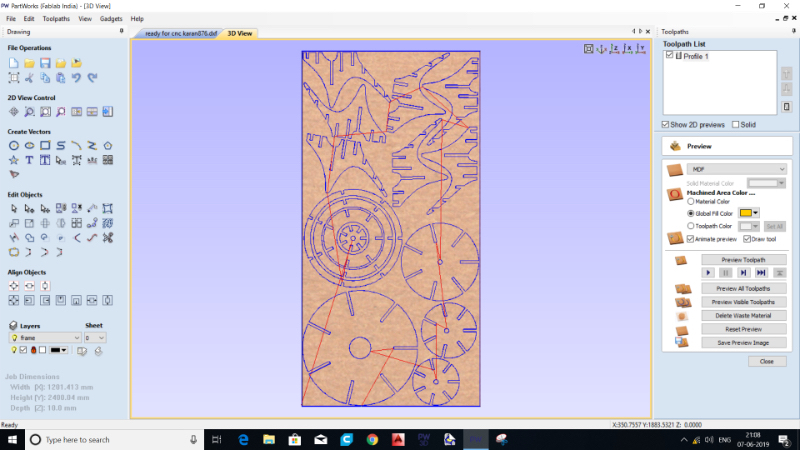
Step 5 : Then put tabs and dogbone parameters etc. Then go to next step.
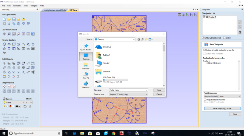
Step 6 : Then click on save tool path as given below.
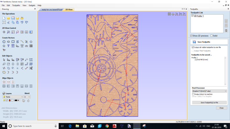
Step 7 : The dilogue below will appear.
3. Turn On Machine.
Then Open ShopBot App (Here ShopBot 3). Will appear as below.
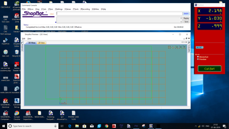
4. Setting X,Y,Z and Origin.
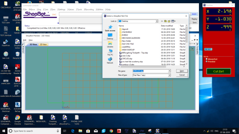
Then on second window go to 'Cut Part'. Then Select the .sbp file and start and follow on-screen notifications.
5. Start the Exaust.
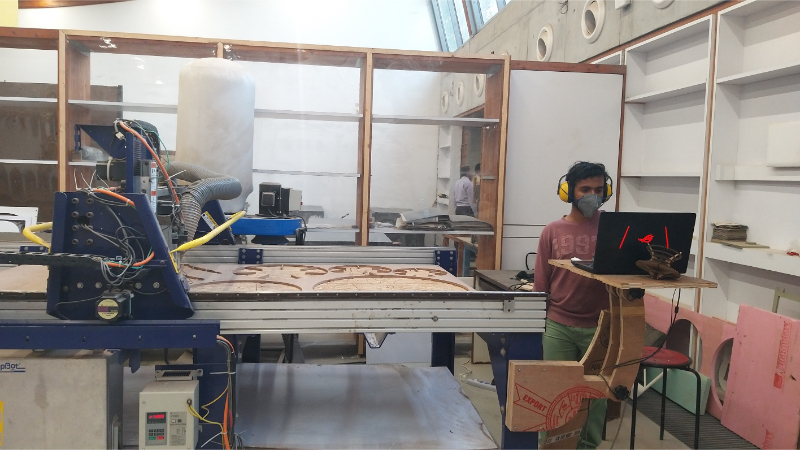
6. Supervise the process.
7. Turn of the process and let head go to its place. Unmount the material.
8. Demount. Remove parts and assemble it.
Final Output
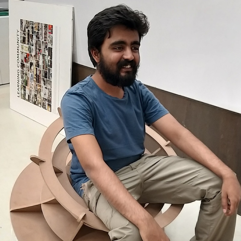
Contribution To Group Work
This week we tested various parameters. I contributed in machining process and supervising the machining and documenting and helped in taking pictures and analysing.
What Did I Learn?
Initial challenge was to modify design and optimise design. For that I changed corners that touch ground and modified curves.
Other challenge was how to make it usable and make it precise. For that I reffered to our Group Work's Results. And tried to find tolerence. Thus material thickness was 11 mm so I kept tolerance of 12 mm. (Keeping Exxact in MDF Won't Work.)
Also I found that PathWorks automatically identifies In and out in opposite direction in case of concentric modules. Thus do not make different cut files in that case otherwise there will be errors.