This week is Embedded Programming. I must say its a very new topic for me and has a lot to learn. Neil started the lecture with a different type of architecture of a microcontroller. Then we discussed the memory and peripherals of the microcontrollers. Then he spoke about the different families they are being classified into and the vendor details for the same.
This week I read data sheet and tried to summarize what is important and how to choose a microcontroller for givenn purpose.
Data Sheet
A datasheet, data sheet, or spec sheet is a document that summarizes the performance and other technical characteristics of a product, machine, component (e.g., an electronic component), material, a subsystem (e.g., a power supply) or software in sufficient detail that allows design engineer to understand the role of the component in the overall system. Typically, a datasheet is created by the manufacturer and begins with an introductory page describing the rest of the document, followed by listings of specific characteristics, with further information on the connectivity of the devices. In cases where there is relevant source code to include, it is usually attached near the end of the document or separated into another file.
What does Data Sheet contain ?
Data Sheet of MicroController Contains :
Manufacturer's name.
Product number and name.
List of available package formats (with images) and ordering codes.
Notable device properties.
Short functional description.
Pin connection diagram.
Absolute minimum and maximum ratings (supply voltage, power consumption, input currents, temperatures for storage, operating, soldering, etc.)
Recommended operating conditions (as absolute minimum and maximum ratings)
DC specifications (various temperatures, supply voltages, input currents, etc.)
Maximum power consumption over the whole operating temperature range.
AC specifications (various temperatures, supply voltages, frequencies, etc.)
Input/output wave shape diagram.
Timing diagram.
Some characteristics are only given at a specific temperature, typically 25 °C (77 °F)
Physical details showing minimum/typical/maximum dimensions, contact locations and sizes.
Ordering codes for differing packages and performance criteria.
Liability disclaimer regarding device use in certain environments such as nuclear power plants and life support systems.
Application recommendations, such as required filter capacitors, circuit board layout, etc.
What Factors Are Important to choose Micro-Controller?
Memory
Temperature
Pin Configuration
Clock Speed
Chip Architecture
Special Features
I have read three datasheets and below I have compared various specification of three Microcontrollers by ATMEL.
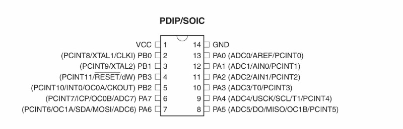
ATtiny22/44/84
Features
• High Performance, Low Power AVR® 8-Bit Microcontroller • Advanced RISC Architecture
– 120 Powerful Instructions – Most Single Clock Cycle Execution – 32 x 8 General Purpose Working Registers
– Fully Static Operation
• Non-volatile Program and Data Memories
– 2/4/8K Byte of In-System Programmable Program Memory Flash (ATtiny24/44/84)
Endurance: 10,000 Write/Erase Cycles
– 128/256/512 Bytes In-System Programmable EEPROM (ATtiny24/44/84)
Endurance: 100,000 Write/Erase Cycles
– 128/256/512 Bytes Internal SRAM (ATtiny24/44/84)
– Programming Lock for Self-Programming Flash Program and EEPROM Data
Security
• Peripheral Features
– Two Timer/Counters, 8- and 16-bit counters with two PWM Channels on both – 10-bit ADC
8 single-ended channels
12 differential ADC channel pairs with programmable gain (1x, 20x) Temperature Measurement
– Programmable Watchdog Timer with Separate On-chip Oscillator – On-chip Analog Comparator
– Universal Serial Interface
• Special Microcontroller Features
– debugWIRE On-chip Debug System
– In-System Programmable via SPI Port
– External and Internal Interrupt Sources
– Pin Change Interrupt on 12 pins
– Low Power Idle, ADC Noise Reduction, Standby and Power-down Modes – Enhanced Power-on Reset Circuit
– Programmable Brown-out Detection Circuit
– Internal Calibrated Oscillator
– On-chip Temperature Sensor
• I/O and Packages
– 14-pin SOIC, PDIP and 20-pin QFN/MLF: Twelve Programmable I/O Lines
• Operating Voltage:
– 1.8 - 5.5V for ATtiny24V/44V/84V – 2.7 - 5.5V for ATtiny24/44/84
• Industrial Temperature Range • Low Power Consumption
– Active Mode:
1 MHz, 1.8V: 380 μA
– Power-down Mode: 1.8V: 100 nA
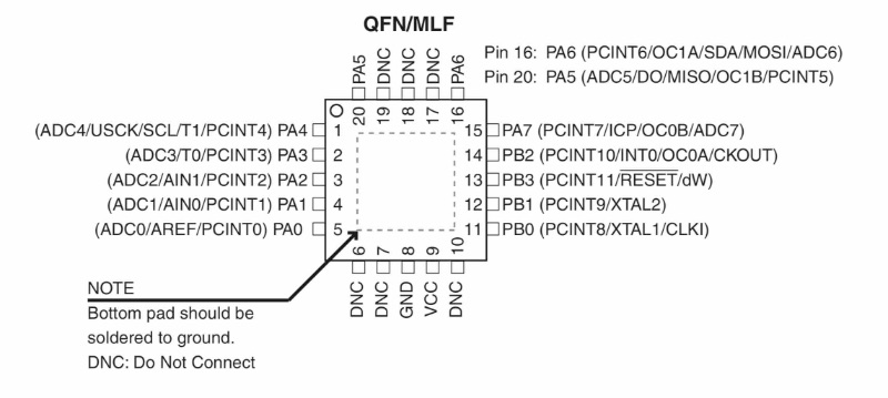
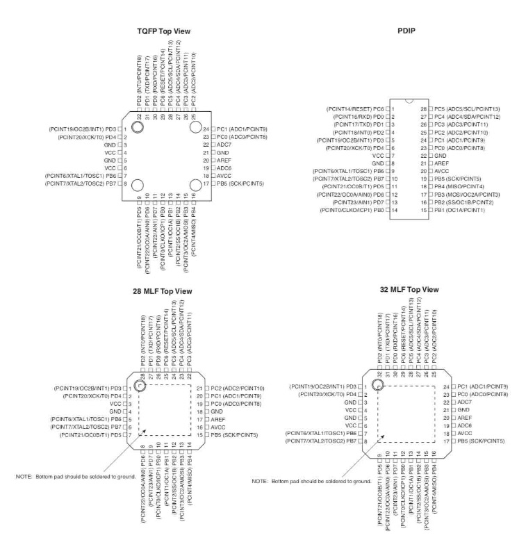
Pinout
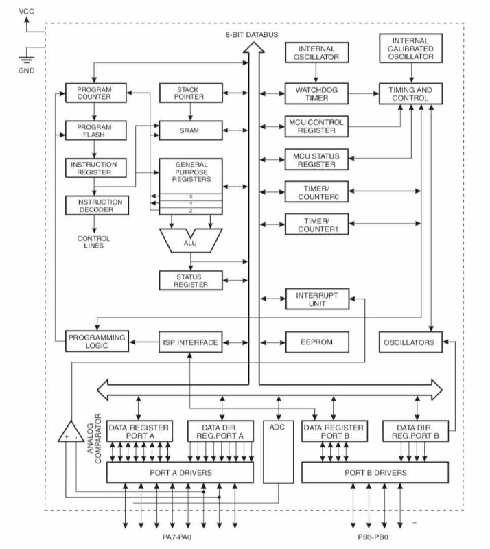
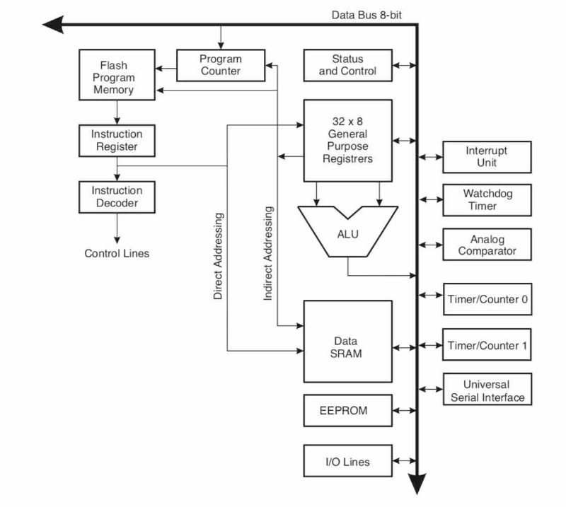
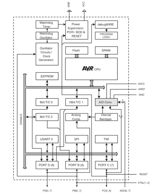
Architecture and Block Diagram
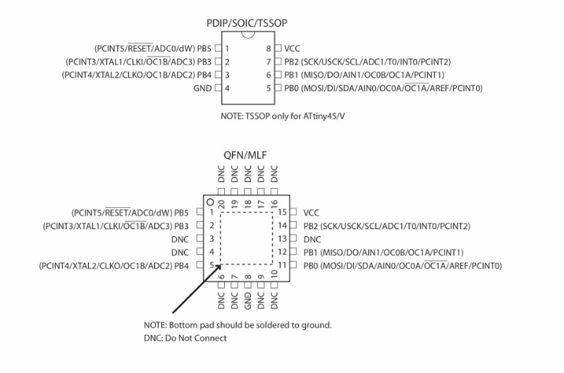
ATtiny25/45/85
Features
• High Performance, Low Power AVR® 8-Bit Microcontroller • Advanced RISC Architecture
– 120 Powerful Instructions – Most Single Clock Cycle Execution – 32 x 8 General Purpose Working Registers
– Fully Static Operation
• Non-volatile Program and Data Memories
– 2/4/8K Byte of In-System Programmable Program Memory Flash (ATtiny25/45/85)
Endurance: 10,000 Write/Erase Cycles
– 128/256/512 Bytes In-System Programmable EEPROM (ATtiny25/45/85)
Endurance: 100,000 Write/Erase Cycles
– 128/256/512 Bytes Internal SRAM (ATtiny25/45/85)
– Programming Lock for Self-Programming Flash Program and EEPROM Data
Security
• Peripheral Features
– 8-bit Timer/Counter with Prescaler and Two PWM Channels – 8-bit High Speed Timer/Counter with Separate Prescaler
2 High Frequency PWM Outputs with Separate Output Compare Registers
Programmable Dead Time Generator
– USI – Universal Serial Interface with Start Condition Detector – 10-bit ADC
4 Single Ended Channels
2 Differential ADC Channel Pairs with Programmable Gain (1x, 20x) Temperature Measurement
– Programmable Watchdog Timer with Separate On-chip Oscillator
– On-chip Analog Comparator • Special Microcontroller Features
– debugWIRE On-chip Debug System
– In-System Programmable via SPI Port
– External and Internal Interrupt Sources
– Low Power Idle, ADC Noise Reduction, and Power-down Modes – Enhanced Power-on Reset Circuit
– Programmable Brown-out Detection Circuit
– Internal Calibrated Oscillator
• I/O and Packages
– Six Programmable I/O Lines
– 8-pin PDIP, 8-pin SOIC and 20-pad QFN/MLF
• Operating Voltage
– 1.8 - 5.5V for ATtiny25/45/85V – 2.7 - 5.5V for ATtiny25/45/85
r
• Industrial Temperature Range • Low Power Consumption
– Active Mode:
1 MHz, 1.8V: 300 μA
– Power-down Mode: 0.1μA at 1.8V
Pinout
Architecture and Block Diagram
ATtiny 44 vs 45 Pinout Configuration
ATmega48P/ATmega88P/ATmega168P/ATmega328P
Features
• High Performance, Low Power AVR® 8-Bit Microcontroller • Advanced RISC Architecture
– 131 Powerful Instructions – Most Single Clock Cycle Execution – 32 x 8 General Purpose Working Registers
– Fully Static Operation
– Up to 20 MIPS Throughput at 20 MHz
– On-chip 2-cycle Multiplier
• High Endurance Non-volatile Memory Segments
– 4/8/16/32K Bytes of In-System Self-Programmable Flash progam memory (ATmega48P/88P/168P/328P)
– 256/512/512/1K Bytes EEPROM (ATmega48P/88P/168P/328P)
– 512/1K/1K/2K Bytes Internal SRAM (ATmega48P/88P/168P/328P)
– Write/Erase Cycles: 10,000 Flash/100,000 EEPROM
– Data retention: 20 years at 85°C/100 years at 25°C(1)
– Optional Boot Code Section with Independent Lock Bits
In-System Programming by On-chip Boot Program
True Read-While-Write Operation
– Programming Lock for Software Security
• Peripheral Features
– Two 8-bit Timer/Counters with Separate Prescaler and Compare Mode
– One 16-bit Timer/Counter with Separate Prescaler, Compare Mode, and Capture
Mode
– Real Time Counter with Separate Oscillator
– Six PWM Channels
– 8-channel 10-bit ADC in TQFP and QFN/MLF package
Temperature Measurement
– 6-channel 10-bit ADC in PDIP Package
Temperature Measurement
– Programmable Serial USART
– Master/Slave SPI Serial Interface
– Byte-oriented 2-wire Serial Interface (Philips I2C compatible)
– Programmable Watchdog Timer with Separate On-chip Oscillator
– On-chip Analog Comparator
– Interrupt and Wake-up on Pin Change
• Special Microcontroller Features
– Power-on Reset and Programmable Brown-out Detection
– Internal Calibrated Oscillator
– External and Internal Interrupt Sources
– Six Sleep Modes: Idle, ADC Noise Reduction, Power-save, Power-down, Standby,
and Extended Standby • I/O and Packages
– 23 Programmable I/O Lines
– 28-pin PDIP, 32-lead TQFP, 28-pad QFN/MLF and 32-pad QFN/MLF • Operating Voltage:
– 1.8 - 5.5V for ATmega48P/88P/168PV – 2.7 - 5.5V for ATmega48P/88P/168P – 1.8 - 5.5V for ATmega328P
r
As I have read the datasheet here I will list down all the things that are important and how does it help ? :
Why Did I choose AtTiny 44 for Hello Echo ?
The simple hello echo board that I wanted to make doesn't run on heavy sized program. Thus AtTiny44 Memory is enough to perform that.
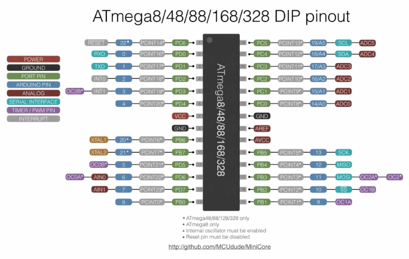
What pin does what ?
Here I have poined out what pin is for what :
Pin
Full Form
Function
VCC
Voltage at Common Connector
Supply Voltage
GND
Ground
Reference point in an electrical circuit from which voltages are measured, a common return path for electric current
SCK
Serial Clock), (SPI Bus Serial Clock)
This is the clock shared between this controller and other system for accurate data transfer.[Serial Peripheral Interface (SPI) for programming]
RST
Reset
Pin by default is used as RESET pin. The pin active low.
MOSI
(Master Output Slave Input).
When controller acts as slave, the data is received by this pin.
SDA
Serial Data Pin
Two-wire Serial Bus Data Input/output Line
MISO
Master Input Slave Output
When controller acts as slave, the data is sent to master by this controller through this pin.
SCK
SPI Bus Serial Clock
This is the clock shared between this controller and other system for accurate data transfer.
SCL
SPI Bus Serial Clock
Two-wire Serial Bus Clock Line
MISO
Master Input Slave Output
When controller acts as slave, the data is sent to master by this controller through this pin.
XTAL1,XTAL2
Chip Clock Oscillator pin 1 and 2
Used with external chip oscillator.
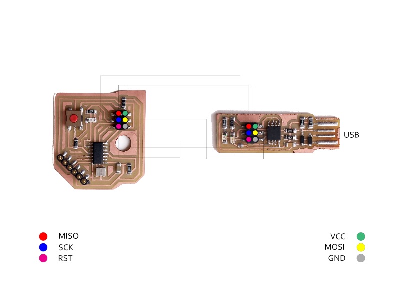
I used MISO, MOSI, SCK, RST, VCC, AND GRD pin for standard 6 pin header programmer ISP.
XTAL1 and XTAL 2 was connected with ends of Oscillator in my board.
SCK was connected to LED to indicate clock status of the board. When you control clock, you're also controlling led. (For eg. delay(500) vs. delay(1000). It blinks at 500 milisecond interval VS blinks at 1000 milisecond interval.
(*Refer to port and circuit diagram for particular to decide on which pin to use where for further reference.)
Programming the Board
This week I programmed my Hello Echo Board. This week I programmed it such that 1. Board LED continously blinks and Stops when Button is pressed. 2. I played with delay and reverting the program. You can see how I made board using link below.
Then we need to comnect FabISP to Board Using 6 pin headers. (Follow ISP header Pinout Diagram)
Then We need ATtiny Liberary for arduino to program. To do that, Go to Arduino> Preferances.
In settings Add following link and save : https://raw.githubusercontent.com/damellis/attiny/ide-1.6.x-boards-manager/package_damellis_attiny_index.json
Go to Tools > Manage Liberaries. Search "attinny" and Install Attiny Liberary.
Now Go to Tools and Select following.
Parameters
Board : ATtiny44 (Or whiever you used in your board)
Processor : ATtiny44
Clock : External 20MHz (You can use internal if board doesn't have external.)
Port : Select port in which board is connected.
Programmer : USBtinyISP (Or whichever programmer you are using.)
Write Code.
Upload program to the board.
Codes
First programmed my board to blink conntinuously at specific interval it stops when pressed button.
		// constants won't change. Used here to set a pin number:
		const int ledPin =  LED_BUILTIN;
		// the number of the LED pin

		// Variables will change:
		int ledState = LOW;
		// ledState used to set the LED

		// Generally, you should use "unsigned long" for variables that hold time
		// The value will quickly become too large for an int to store
		unsigned long previousMillis = 0;
		 // will store last time LED was updated

		// constants won't change:
		const long interval = 1500;
		 // interval at which to blink (milliseconds)

		void setup() {
		 // set the digital pin as output:
		 pinMode(ledPin, OUTPUT);
	   }

		void loop() {
		 // here is where you'd put code that needs to be running all the time.

		 // check to see if it's time to blink the LED; that is, if the difference
		 // between the current time and last time you blinked the LED is bigger than
		 // the interval at which you want to blink the LED.
		 unsigned long currentMillis = millis();

		 if (currentMillis - previousMillis >= interval) {
		   // save the last time you blinked the LED
		   previousMillis = currentMillis;

		   // if the LED is off turn it on and vice-versa:
		   if (ledState == HIGH) {
			 ledState = LOW;
		   } else {
			 ledState = HIGH;
		   }

		   // set the LED with the ledState of the variable:
		   digitalWrite(ledPin, ledState);
		 }
	   }
Second I programmed to blink board with delay.
		int led = 4;
		int button =2;
		int state=0;

		void setup() {
		  // put your setup code here, to run once:


		  pinMode(led, OUTPUT);
		  pinMode(button, INPUT);
		  digitalWrite(led, LOW);
		}

		void loop() {
		  // put your main code here, to run repeatedly:

		  state= digitalRead(button);
		  if(state==1){
			digitalWrite(led, HIGH);
			delay(1000);
		  }
		  else{
			digitalWrite(led, LOW);
			delay(1000);
		  }

		}
Video
What Did I learn ?
This week I read data sheet and learned various things about microcontroller.
I learned about various syntax and tags of Arduino C.