The week was about Sensors. The week was about understanding input devices and using them in a circuit to measure something. Neil started with the type of connections for input devices and jumped into different input devices, classified as per their field.
What is an Input Device?
"An input device is a piece of computer hardware equipment used to provide data and control signals to an information processing system such as a computer or information appliance."
In Fab Acadmemy, mostly We use Sensors as Input Devices.
Sensors
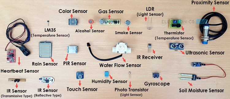
There are manny types of sensors on basis of its property or usage.
Below is the list of few commonn sensors :
Sensor
Description
Temperature Sensor
This device collects information about temperature from a source and converts into a form that is understandable by other device or person.
There are two basic types of temperature sensors:
Contact Sensors – This type of sensor requires direct physical contact with the object or media that is being sensed. They supervise the temperature of solids, liquids and gases over a wide range of temperatures.
Non contact Sensors – This type of sensor does not require any physical contact with the object or media that is being sensed. They supervise non-reflective solids and liquids but are not useful for gases due to natural transparency.
Proximity Sensor
A proximity sensor detects the presence of objects that are nearly placed without any point of contact. Since there is no contact between the sensors and sensed object and lack of mechanical parts, these sensors have long functional life and high reliability.
IR Sensor (Infrared Sensor)
This device emits and/or detects infrared radiation to sense a particular phase in the environment. Generally, thermal radiation is emitted by all the objects in the infrared spectrum. The infrared sensor detects this type of radiation which is not visible to human eye.
Advantages :
- Easy for interfacing
- Readily available in market
Disadvantages :
· Disturbed by noises in the surrounding such as radiations, ambient light etc.
Pressure Sensor
A pressure sensor is a device which senses pressure and converts it into an analog electric signal whose magnitude depends upon the pressure applied. Since they convert pressure into an electrical signal, they are also termed as pressure transducers.
Light Sensor
A Light Detector or a Light Sensor is a device or circuit that detects the intensity of the light incident on it. Different types of light detectors are LDRs (or Light Dependent Resistors), Photo Diodes, Photo Transistors, etc.
All these devices are called as Photoelectric Devices as they convert light energy to electric energy. These Light Detectors or Sensors can detect different types of light like visible light, ultraviolet light, infrared light etc.
Ultrasonic Sensor
As the name indicates, ultrasonic sensors measure distance by using ultrasonic waves.
The sensor head emits an ultrasonic wave and receives the wave reflected back from the target. Ultrasonic Sensors measure the distance to the target by measuring the time between the emission and reception.
Distance L = 1/2 × T × C
where L is the distance, T is the time between the emission and reception, and C is the sonic speed. (The value is multiplied by 1/2 because T is the time for go-and-return distance.)
Smoke Sensor
There are two types of smoke detectors. Optical or Photoelectric smoke detectors and Ionization smoke detectors.
Optical smoke detectors consists of a light source like LED and a light detector like photocell.
The photocell conducts as long as the light falls on it. When there is smoke, the light from the source is interrupted and the photocell doesn’t conduct.
Ionization smoke detectors consists of two electrodes and an ionization chamber filled with ions. When there is no smoke, the ions move freely and the electrodes conduct normally.
Alcohol Sensor
Breath Alcohol Tester is a device that is used to indicate or estimate the blood alcohol content of a person. The general term for this device is Breathalyzer or Breath Analyzer.
Touch Sensor
A touch sensor acts as a variable resistor as per the location where it is touched.
Color Sensor
A Color Sensor, as the name suggests, is a device that senses or detects colors. A color sensor will use an external means of emitting light (like an array of white LEDs) and then analyse the reflected light from the object in order to determine its color.
Humidity Sensor
This sensor measures the humidity of surrounding.
Tilt Sensor
Tilt sensors measure the tilting position with reference to gravity and are used in numerous applications. They enable the easy detection of orientation or inclination.
The functionality of tilt sensors is influenced by factors such as gravity, vibration, temperature, zero offset, linearity, cross-axis sensitivity, acceleration/deceleration, shock, clear line of sight between the user and the measured point, and calibration of tilt sensors.
Types of Sensors
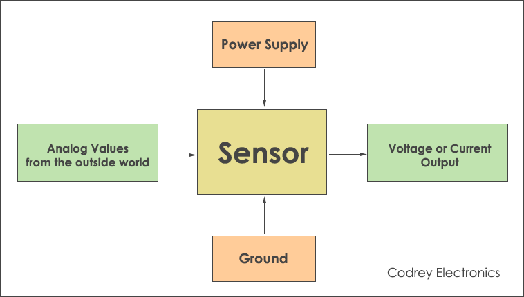
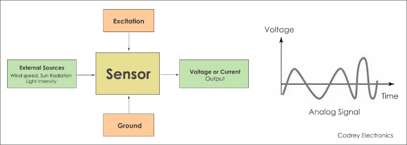
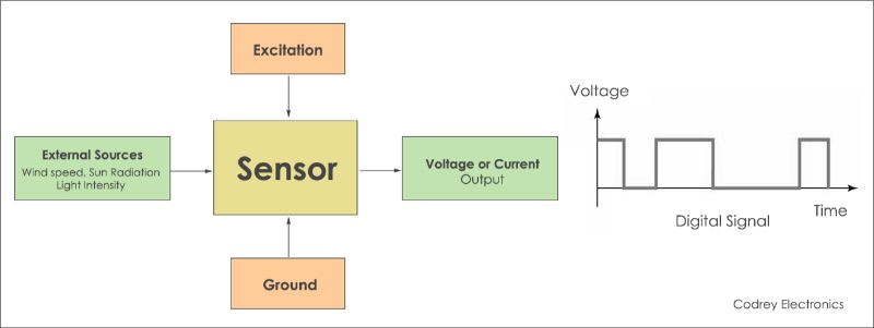
Analogue Sensors
Analog Sensors produce a continuous output signal or voltage which is generally proportional to the quantity being measured. Physical quantities such as Temperature, Speed, Pressure, Displacement, Strain etc are all analog quantities as they tend to be continuous in nature. For example, the temperature of a liquid can be measured using a thermometer or thermocouple which continuously responds to temperature changes as the liquid is heated up or cooled down.
Digital Sensors
As its name implies, Digital Sensors produce a discrete digital output signals or voltages that are a digital representation of the quantity being measured. Digital sensors produce a Binary output signal in the form of a logic “1” or a logic “0”, (“ON” or “OFF”). This means then that a digital signal only produces discrete (non-continuous) values which may be outputted as a single “bit”, (serial transmission) or by combining the bits to produce a single “byte” output (parallel transmission).
Using Flex Sensor
What is Flex Sensor ?
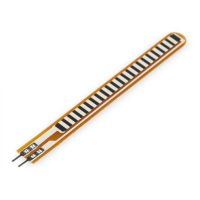
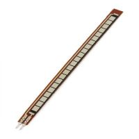
This flex sensor is a variable resistor like no other. The resistance of the flex sensor increases as the body of the component bends. Sensors like these were used in the Nintendo Power Glove. They can also be used as door sensors, robot whisker sensors, or a primary component in creating sentient stuffed animals.
Flex sensors are available in two sizes: one 2.2" (5.588cm) long and another coming in at 4.5" (11.43cm) long.
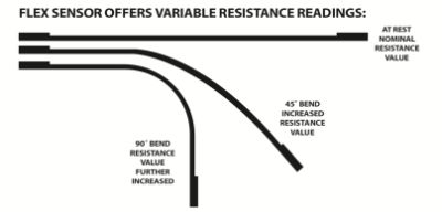
Left flat, these sensors will look like a 30kΩ resistor. As it bends, the resistance between the two terminals will increase to as much as 70kΩ at a 90° angle.
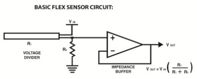
By combining the flex sensor with a static resistor to create a voltage divider, you can produce a variable voltage that can be read by a microcontroller's analog-to-digital converter.
I wanted to use flex sensor as my input device for my Final Project.
I wanted to try it out and understand it properly in this week. Thus I decided to make one and also buy one. To understannd the difference and working of it.
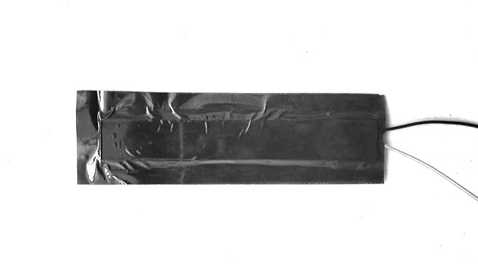
How to make Flex Sensor?
Making a flex sensor is very easy and very affordable than buying. But the accuracy is comparitively very low and uneven.
But you can make and use it for testing and prototyping.
Process :
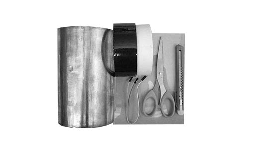
For makinnng it you need following materials:
Tape (Non Conductive)
Copper Sheet/Conductive Sheet
Flexible Plastic
Paper
Pencil
Two Wires
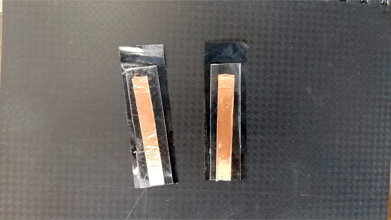
Step 1 : The first step is to measure the size desired(size of your finger) and then cut the plastic, paper and copper in that size.
Step 2 : Use a dark pencil and scribbled over the paper on both sides. This is very important as this is the resistive material that is used to measure the resistance.
Note : Darker the scribble the better the sensor.
Step 3 : Stick the parts as following.
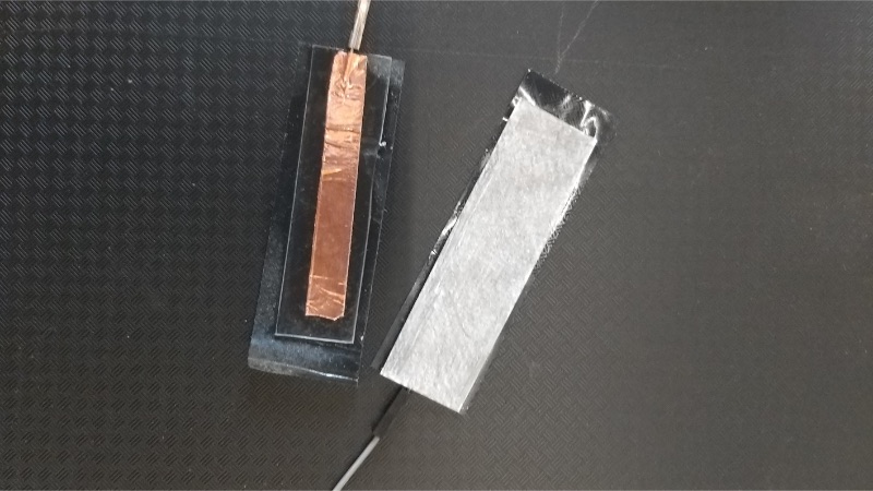
Step 4 : Solder end of wire on copper parts. And stick over resistance paper on one side.
Step 5 : Stick both ends to eachother and its ready.
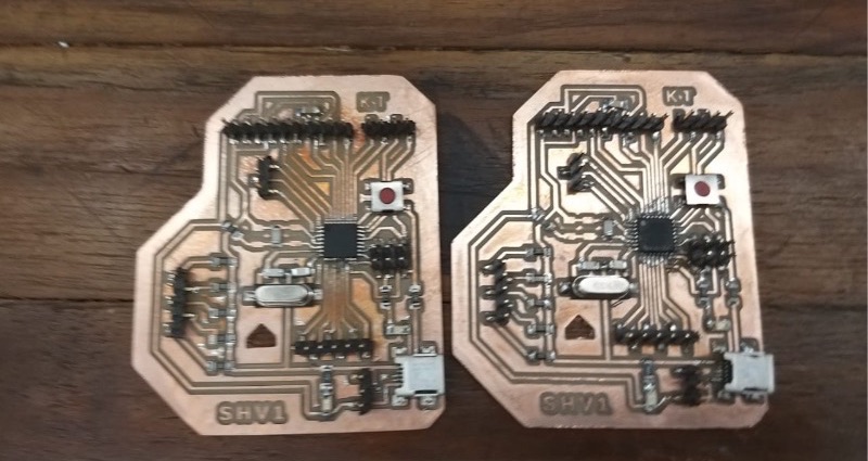
Designing the board
I used the board using certain important things in mind.
Below is the list of things I required my board to do :
The other board worked OK with the Flex I made but, it didn't work with the purchased Flex sensor.
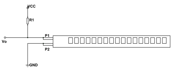
Then I checked Circuit Diagram for the same. I had to attach resistors to analog pin.
The flex diagram is as below.
The R1 value could vary according to difference you want. Minimun is suggested at 10K Ohm.
A flex sensor has a range from about ~10K to ~35K, that means it won't give us a full 0-5 volt range (or 0-1023 analog value).
It performs better with 22K ohm Value resistor.
I used 22K Ohm as I wanted more range in values.
I used same board for both videos to compare the data and performance.
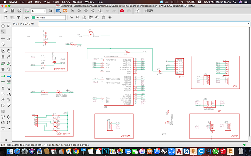
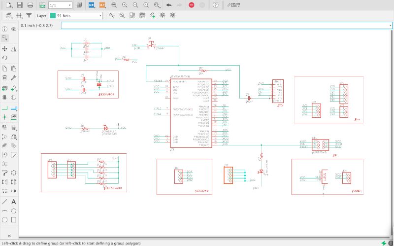
Schematic
I made schematic modular and easy to understand and navigate by others. I labelled eachmodule for that.
Each has its significance on its own and in system.
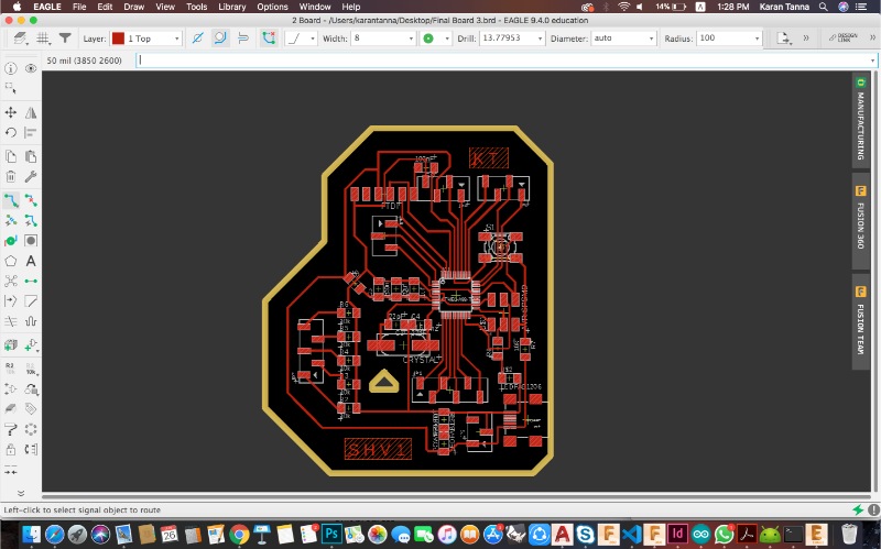
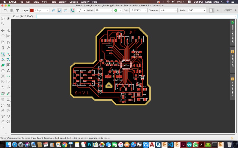
Board Diagram
Setting Up DRC
Note : This is significant part of board design and should be practised before actually milling the board.
What is DRC?
It is Design Rule Check. The set of rules are kept in order to get appropiate board.
How to set DRC?
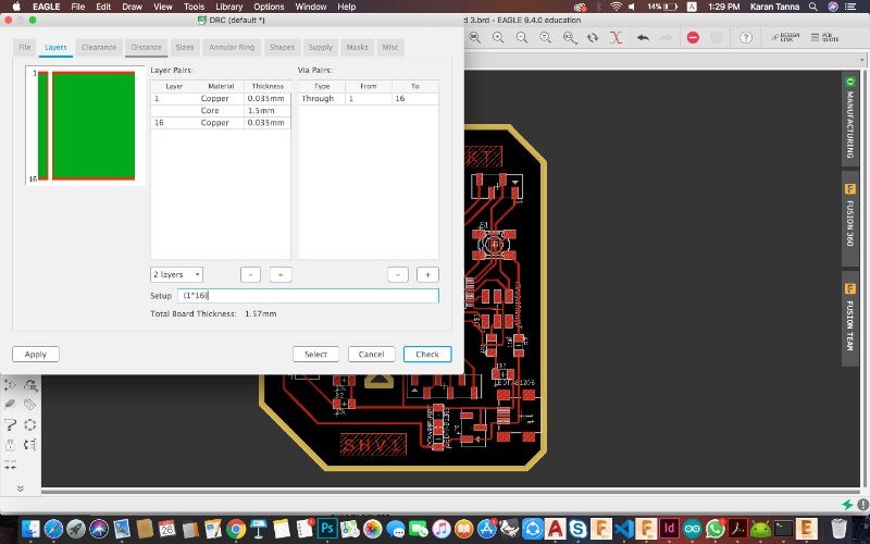
1. Go to Tools> DRC.
The dialogue box like below will open up.
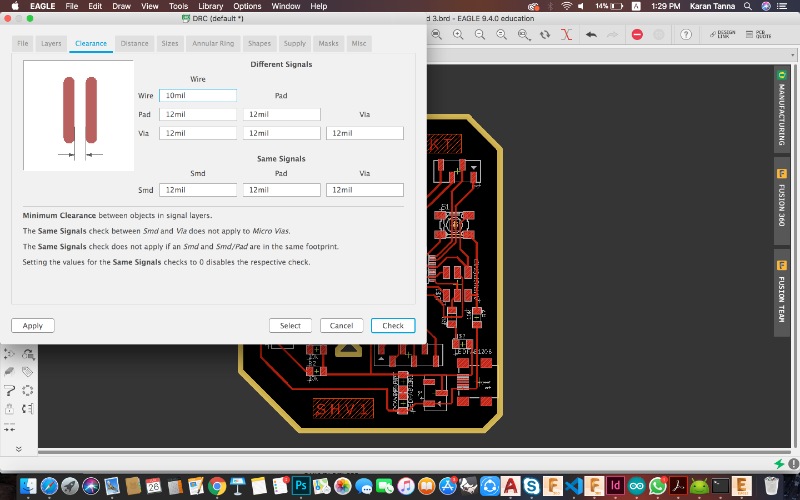
Here important parameter is clearance.
My pads are 12mill for 328p (From Library).And my smallest wire was to be thus I gave clearance of 10mill. And for others 12mill.
Inital width was 10miil-12mill.(Near 328p) Then you can further increase it if you need.
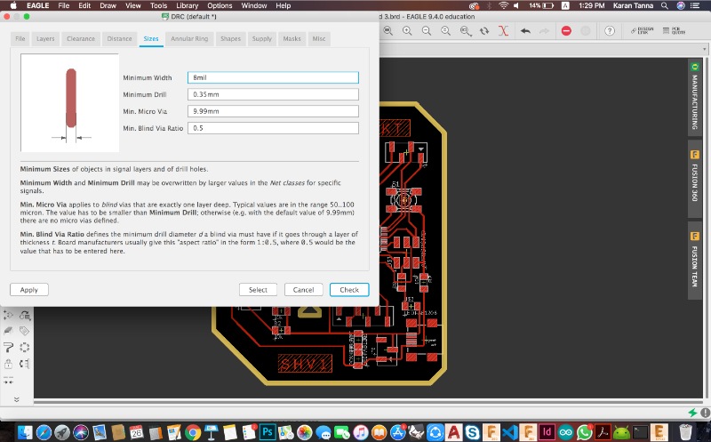
Minimum width : 8mill-10mill for MCU like 328P.
After this Save it.
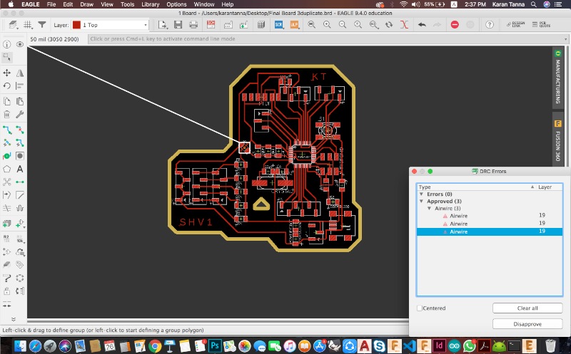
Error Check
You can check and fix errors from Tools>Errors. It will list all the errors.
Exeptions
You can approve air-wire errors like here in example, it is jumper. Thus both ends goes to same kind of traces. But Eagle doesn't know we have used it as jumper. Thus you can approve it manually.
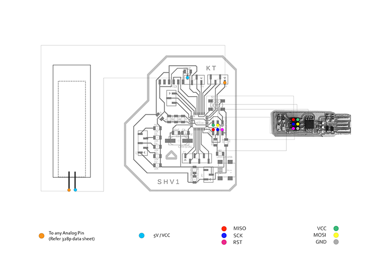
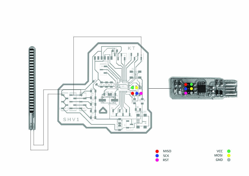
Pinout for the New board
*I used FTDI Cable to monitor with serial as well as power the board.
Using Serial Monitor to Measure the Values
The Code : Filtering Value
I used following code to run the flex sensor in Arduino IDE.
This code measures the value and theThreshold Value (100 for DIY flex and 250 for purchased flex.) turns LED on when it reaches above it.
int flex = A0;


	void setup() {
	  // put your setup code here, to run once:
	  Serial.begin(9600);
	  pinMode(flex, INPUT);
	  pinMode(13,OUTPUT);

	}

	void loop() {
	  // put your main code here, to run repeatedly:
	  int a = analogRead(flex);
	  Serial.print(a);
	  Serial.println("flex");
	if(a > 100) // 250 for readymade flex sensor
	{
	  digitalWrite(13,HIGH);
	  delay(200);
	}
	else{
	  digitalWrite(13,LOW);
	  delay(100);
	}
	}
Serial Monitor
The following video shows the serial values of flex sensor.
You can monitor those values by clicking on top right corner on Arduino Software.
The one with DIY Flex sensor:
The one with Purchased Flex sensor:
The Code : Measuring Bend Degree
I used following code to run the flex sensor in Arduino IDE.
This code measures the resistence value and it maps the value in degrees with associated resistence.The serial monitor shows them.
	const int FLEX_PIN = A0; // Pin connected to voltage divider output

	// Measure the voltage at 5V and the actual resistance of your
	// resistor, and enter them below:
	const float VCC = 4.98; // Measured voltage of Ardunio 5V line
	const float R_DIV = 47500.0; // Measured resistance of 3.3k resistor

	// Upload the code, then try to adjust these values to more
	// accurately calculate bend degree.
	const float STRAIGHT_RESISTANCE = 22000.0; // resistance when straight, value of resistence
	const float BEND_RESISTANCE = 220000.0; // resistance at 90 deg - measure it using multimeter

	void setup()
	{
	  Serial.begin(9600);
	  pinMode(FLEX_PIN, INPUT);
	}

	void loop()
	{
	  // Read the ADC, and calculate voltage and resistance from it
	  int flexADC = analogRead(FLEX_PIN);
	  float flexV = flexADC * VCC / 1023.0;
	  float flexR = R_DIV * (VCC / flexV - 1.0);
	  Serial.println("Resistance: " + String(flexR) + "ohms");

	  // Use the calculated resistance to estimate the sensor's
	  // bend angle:
	  float angle = map(flexR, 0, BEND_RESISTANCE, 0, 90.0);
	  Serial.println("Bend: " + String(angle) + " degrees");
	  Serial.println();

	  delay(500);
	}
Serial Monitor/Output Video
The video shows the resistence value and corresponding bend degree.
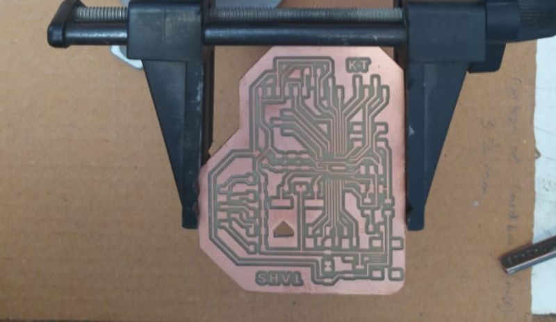
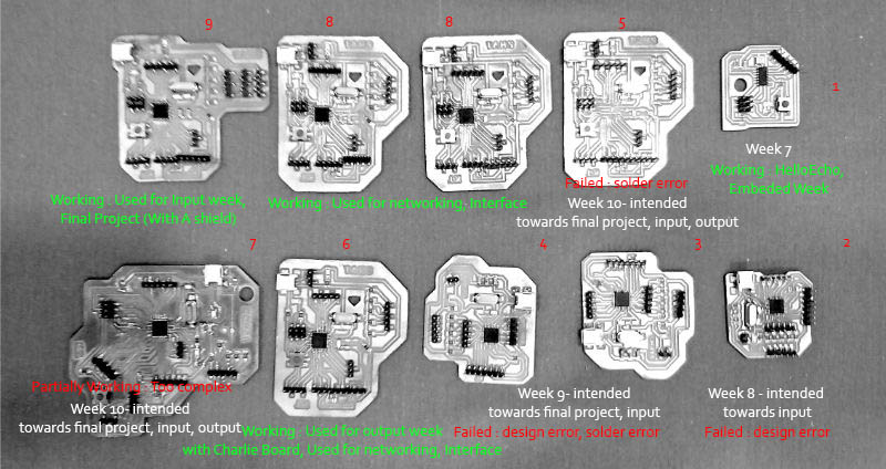
Failures/Attempts/Evolution
I struggled a lot. I had no electronic background. Thus it was very big challange. Also I had to find-out ways of soldering with one hand. Thus after week 7, started making iteration. I had lot of failurs.
I tried making many boards and Improved upon PCB design and soldering.
This week we altogather tested various output devices. We tested power consuption of BLDC motor.
You can visit it by clicking the button at the end of page.
What Did I learn ?
This week I tried to understand Circuit and Schematics.
I researched and learned about laws of electronics and key rules to design circuit.
Since I never used Eagle CAD before, I started to understand workflow of same.
While arranging components in Eagle CAD, I figured that it is easy to route when components are arranged according to modules of schematics.
As I wasn't able to route due to a closed loop, I solved it with 0 ohm resistor and jump over the trace.