This week is all about programming. As I am totally new to programming the lecture made little sense to me. Neil spoke about different languages first and how to communicate with device interfaces. Then he spoke about the functionality of the programs and performance.
What I want to achieve this week ?
I am completely new to programming and was stuck not knowing what to choose. I started with basics. I started tinnkering with MIT App Inventor.
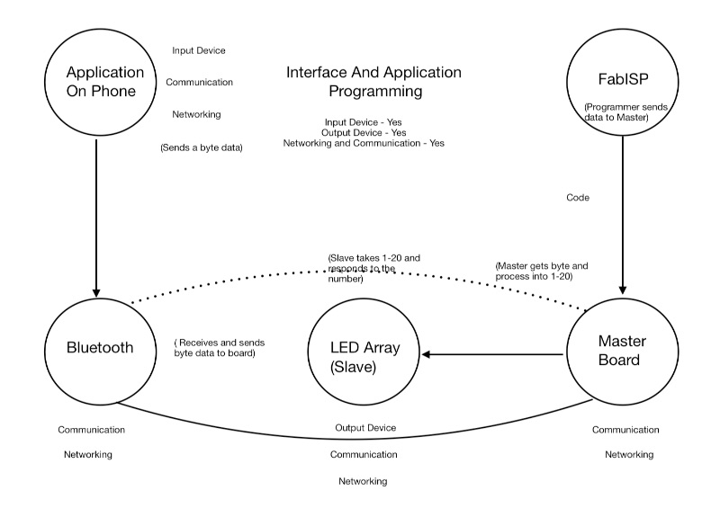
But Wait, I found out that this week could cover total of 4 Fab Academy Weeks : Input Devices, Output Devices, Networking And Communication and also of course Interface and Application Programming.
I would try to show how one project could cover other three weeks.
As mentioned earlier I would try to illustrate learnings of 4 weeeks in one. Below is the diagram showing how ?
Building An App Using MIT App Inventor
MIT App Inventor is an intuitive, visual programming environment that allows everyone – to build fully functional apps for smartphones and tablets. Those new to MIT App Inventor can have a simple first app up and running in less than 30 minutes. And what's more, our blocks-based tool facilitates the creation of complex, high-impact apps in significantly less time than traditional programming environments. The MIT App Inventor project seeks to democratize software development by empowering all people, especially young people, to move from technology consumption to technology creation.
Why AppInventor?
1. Easy To Use
2. Online- No downloads (Also available offline app)
3. Realtime Prototyping of App using an App on phone.
4. Various Plugins and Conncectivity Options.
5. Easy Export(Packaging).
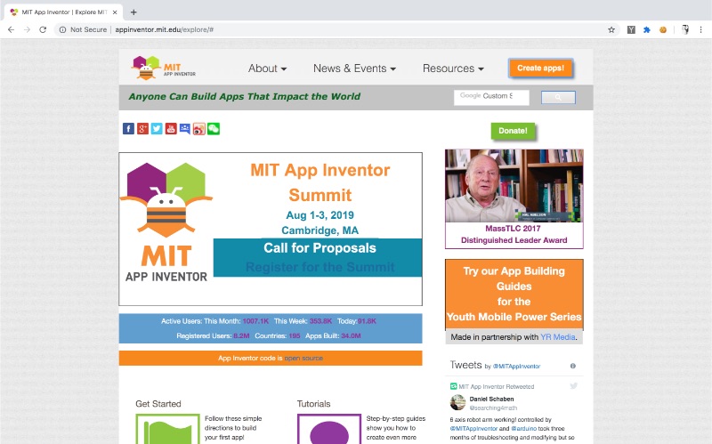
How to Download MIT App Inventor
MIT App Inventor is available online as web app. You can Also download offline for various platforms. It has various extra features like connection using USB, Emulator etc..Below I have given links for the same.
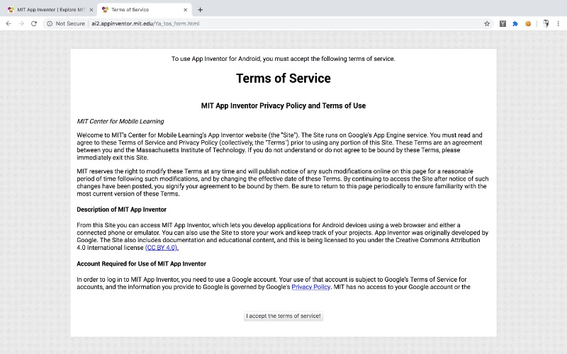
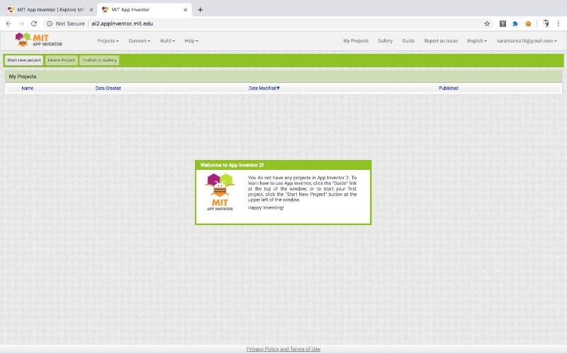
Step 1 : Click Create Apps. Login To MIT App Inventor Using Google ID.
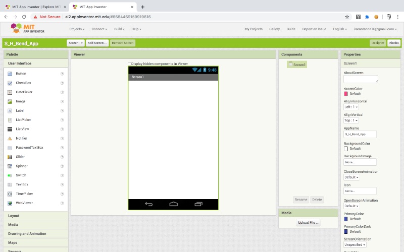
Step 2 : Create Project.
Step 3 : Add Screen.
Step 4 : Add UI elements as you require. From Left Tool Panel. (Drag and Drop.)
You can modify it using Right Panel.
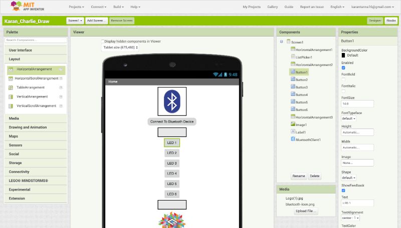
Step 5 : Modify elements as per need. (For Bluetooth, go to connectivity and drag bluetooth client. This is very important.)
Do not forget to use list picker for bluetooth connection.
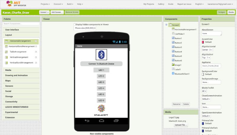
Step 6 : Get done with alignment and compostion of app. (To center align everything go to Scrreen tab on right.)
Completed UI will look like below.
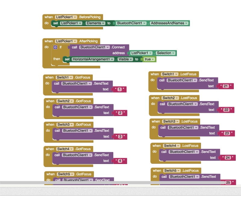
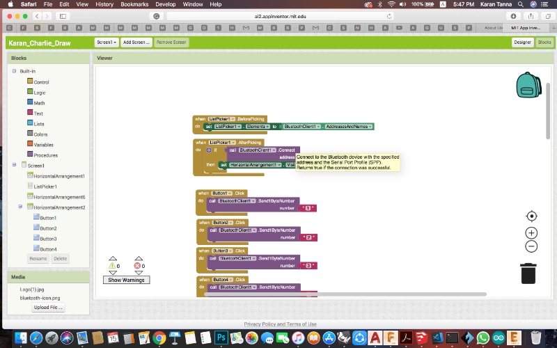
Step 7 : Go to blocks on top-right corner. Here the real thing starts. I struggled through to understand it for some hours.
Step 8 : For bluetooth you require following things.
Step 9 : I required individual program for each button and led control thus I added as above.
I assigned a number to each LED. Total 6 LEDs.
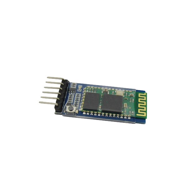
Bluetooth Module (HC-05)
It is used for many applications like wireless headset, game controllers, wireless mouse, wireless keyboard and many more consumer applications.
It has range up to 100m which depends upon transmitter and receiver, atmosphere, geographic & urban conditions.
It is IEEE 802.15.1 standardized protocol, through which one can build wireless Personal Area Network (PAN). It uses frequency-hopping spread spectrum (FHSS) radio technology to send data over air.
It uses serial communication to communicate with devices. It communicates with microcontroller using serial port (USART).
HC-05 is a Bluetooth module which is designed for wireless comunication. This module can be used in a master or slave configuration.
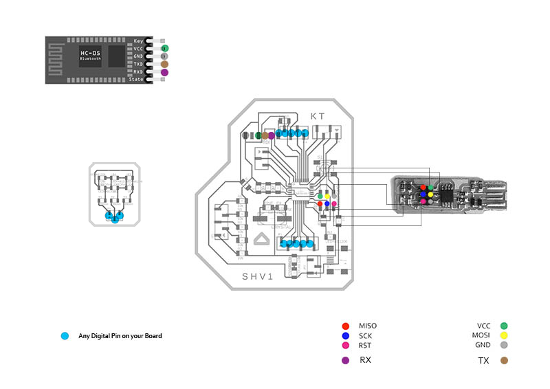
It has 6 pins,
1. Key/EN: It is used to bring Bluetooth module in AT commands mode. If Key/EN pin is set to high, then this module will work in command mode. Otherwise by default it is in data mode.
The default baud rate of HC-05 in command mode is 38400bps and 9600 in data mode.
HC-05 module has two modes,
- Data mode: Exchange of data between devices.
- Command mode: It uses AT commands which are used to change setting of HC-05.
To send these commands to module serial (USART) port is used.
2. VCC: Connect 5 V or 3.3 V to this Pin.
3. GND: Ground Pin of module.
4. TXD: Transmit Serial data (wirelessly received data by Bluetooth module transmitted out serially on TXD pin)
5. RXD: Receive data serially (received data will be transmitted wirelessly by Bluetooth module).
6. State: It tells whether module is connected or not.
Pair HC-05 and smartphone:
Search for new Bluetooth device from your phone. You will find Bluetooth device with “HC-05” name.
Click on connect/pair device option; default pin for HC-05 is 1234 or 0000.
You can learn how to make it by refering the link given below :
Boards
For this weeek I have used boards from Output Week ie. 328p Board and 3X2 tinyplex board.
	#include <SoftwareSerial.h> //Please add angle brackets at the start and end of library. This includes Software Serial liberary.

		#define RX 6 // Defines RX pin
		#define TX 5 // Defines TX pin
		 //Definne RX and TX pins on the microcontroller - connected to bluetooth module


		SoftwareSerial blueToothSerial(RX,TX);  //Defining blueToothSerial input annd output pins
		#define LED_A 0  //LED A row connected to pin 0.
		#define LED_B 1  //LED B row connected to pin 1.
		#define LED_C 2  //LED C row connected to pin 2.


		 //Defining rows connected to pins
		void setup()
		{
		  pinMode(RX, INPUT);
		  pinMode(TX, OUTPUT);
		  pinMode(LED_A, OUTPUT);
		  pinMode(LED_B, OUTPUT);
		  pinMode(LED_C, OUTPUT);


		  // Each set of LED acts as output of Character recieved.

		blueToothSerial.begin(9600);  //Bluetooth Serial
		 delay(2000); //Delay time (in miliseconds)
		 blueToothSerial.println("bluetooth connected!\n"); //Prints when bluetooth serial connected
		 //prints at the begining when blueToothSerial is recieves.
		 delay(2000); // This delay is required.
		 blueToothSerial.flush();

		}

		void loop()
		{

		  int recvChar;
		  while(1)
		  {

		  if(blueToothSerial.available()) //This executes when bluetooth is available.
		  {
			recvChar = blueToothSerial.read(); // Recieves the serial data from the bluetooth.

			//below are the code for individual LED associated with an integer.

			if(recvChar == 1)
			{
			  set_pins(LED_B, LED_A);
			}


			else if(recvChar == 2)
			{
			 set_pins(LED_C, LED_A);
			}


			else if(recvChar == 3)
			{
			  set_pins(LED_A, LED_B);
		  }


			else if(recvChar == 4)
			{
			  set_pins(LED_C, LED_B);
		  }


			else if(recvChar == 5)
			{
			  set_pins(LED_A, LED_C);
		  }


			 else if(recvChar == 6)
			{
			  set_pins(LED_B, LED_C);
		}


		  }
			}

		  }
		  void set_pins(int high_pin, int low_pin)
		{
		  // reset all the pins
		  reset_pins();

		  // set the high and low pins to output
		  pinMode(high_pin, OUTPUT);
		  pinMode(low_pin, OUTPUT);

		  // set high pin to logic high, low to logic low
		  digitalWrite(high_pin, HIGH);
		  digitalWrite(low_pin,LOW);
		}


		 void reset_pins()
		{
		  // start by ensuring all pins are at input and low
		  pinMode(LED_A, OUTPUT);
		  pinMode(LED_B, OUTPUT);
		  pinMode(LED_C, OUTPUT);

		  digitalWrite(LED_A, LOW);
		  digitalWrite(LED_B, LOW);
		  digitalWrite(LED_C, LOW);

		}
I uploaded the code above for individual LED. Below you can see the final output.
Output Video
Thee video below shows demonstration of App & Interface that I made. When you press the button associated to LED it blinks.
Contribution to Group Work
This week I contributed with my exxploration with MIT App Inventor and making UI with App Inventor.
You can see it using the button given for the Group Assignment.
What Did I learn ?
This week I learned about making User Interface for my app and use it and program it.
i Learned MIT App Inventor and how to make it communicate with board.
Also I understood charlieplex code for each LED and how it works.