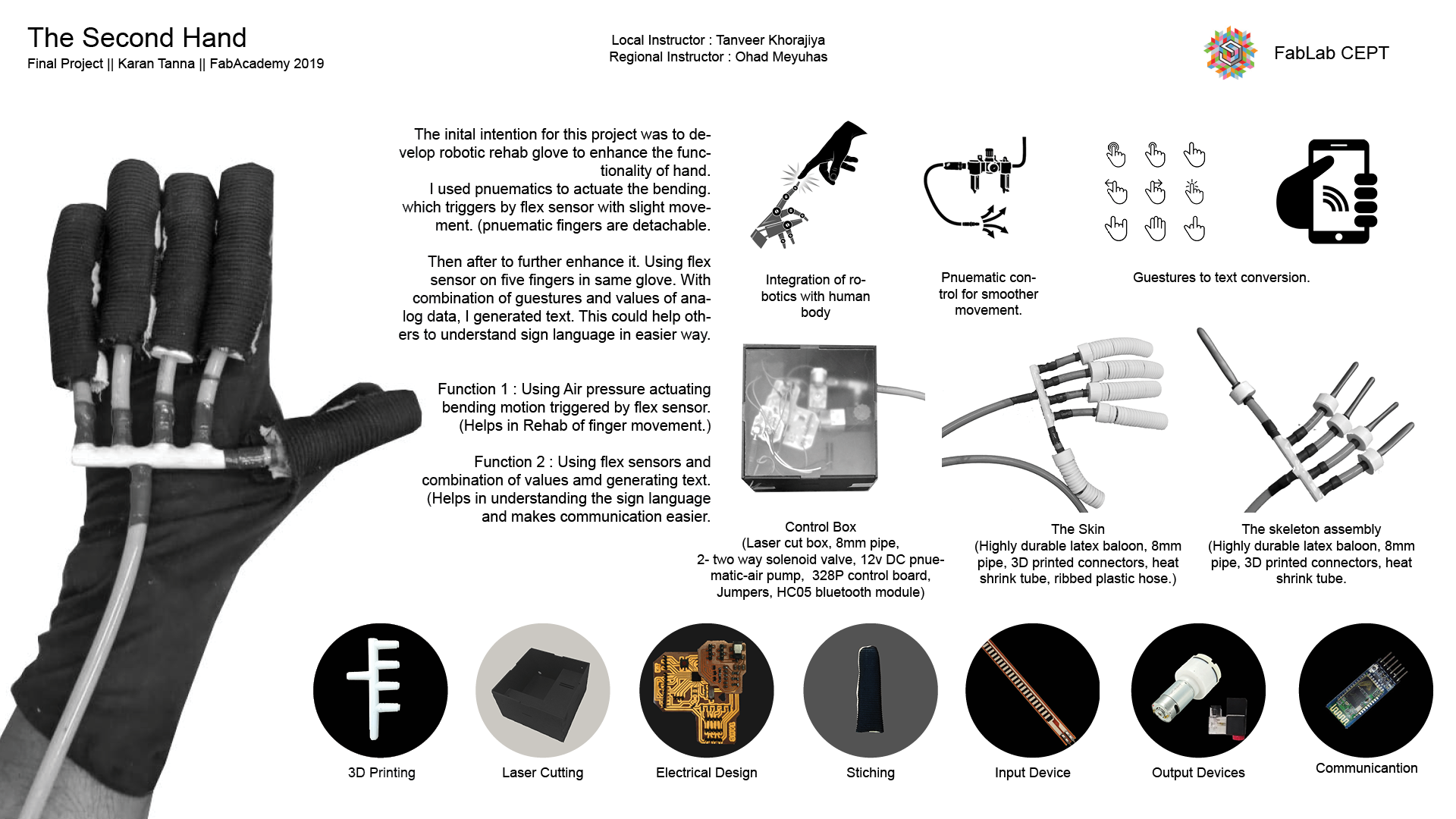
The Second Hand : More Power. Triggered.
Glove for enhancing movement.
Many people must have encountered funcionality or reduced function problem after a fracture or injury. For example someone has got fracture in finger. After recovery his/her finger won’t move as it should. I myself have limited functionality in my right hand. I want to make a device or tool that would help and enhance physical functionality.
My intent for this project is to help people so that they can do more by enhancing the functionality.
For this course of time I would try to achive finger movement.
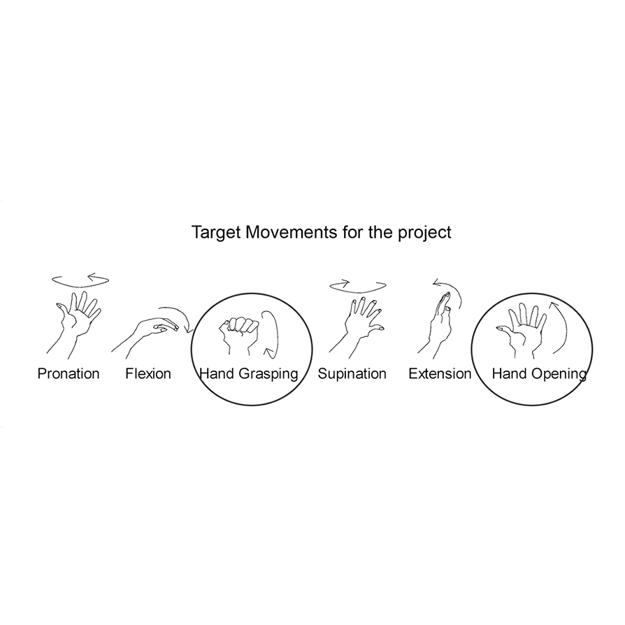
I didn't want to use hard robotics as it requires lot of complicated things and motors and also it uses joints to replicate movement. It doesn't allow a safe room for movement and gives rigit output.
Thus I wanted to go for soft robotics/soft actuators. Thus I went on making pnuematic system.
For any pnuematic system you need pnuematic controller. Thus I wanted my control box to be compact as possible.
First I decided what are necessities for it. The diagram below shows the system.
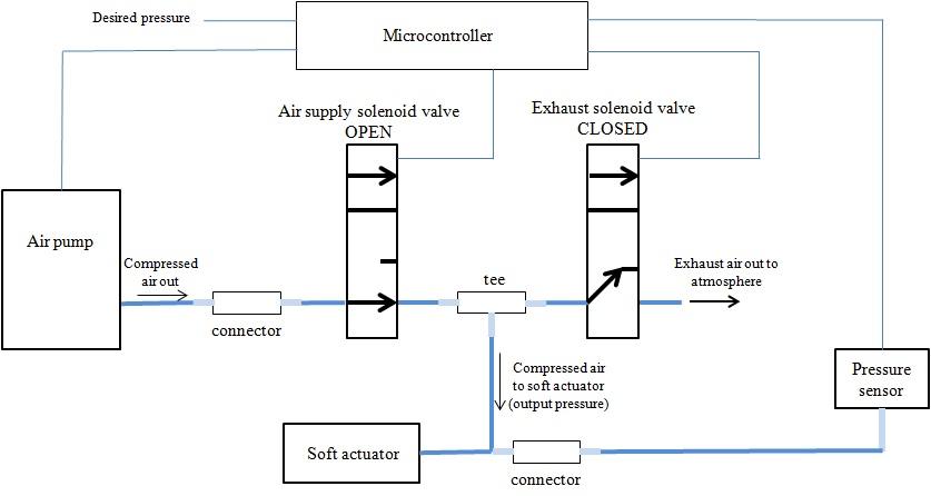
The diagram above shows what I needed. I modified it and I eliminated pressure sensor. Thus Now the control box has 4 main components : 1. Air Pump 2. 2 Two way Solenoid Valves 3. Micro Controller Board & Motor Shield 4. Connectors
First thing First, I ordered components like valves and pump. And then side by side I started designing the board.
I used Eagle 9 for Mac. You can download Eagle using link below. And for more info about using eagle go to Electronic Design Week.
To be able to run flex sensors as input.
To be able to run atleast Two solenoid valves and a DC pump
To be able to run and execute program.
To be able to handle FTDI and I2C connections.
Also I kept in mind other aspects like clock speed and memory etc.
I made schematic modular and easy to understand and navigate by others. I labelled eachmodule for that.
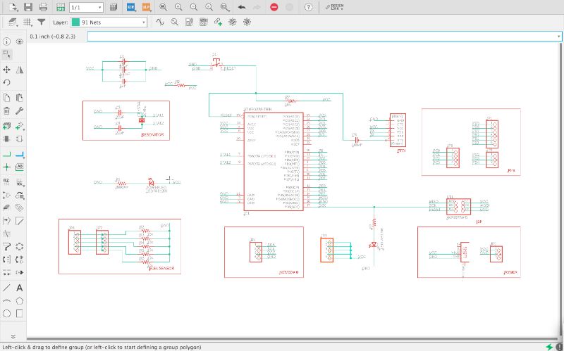
Each has its significance on its own and in system.
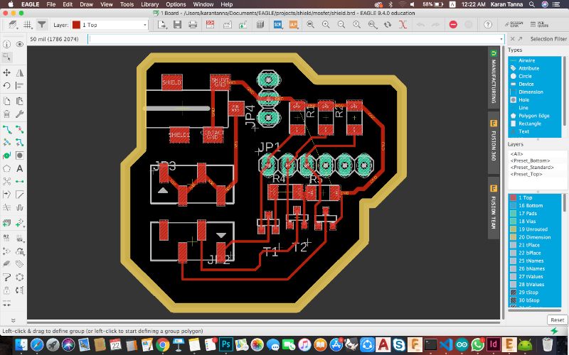
The board diagram in the end took shape according to assembly but I tried to make it as compact as possible. Also I made different layer for the mosfet shield. As I dont need it when I'm just doing Input-Output-Communication week etc.
Board diagram is as below.
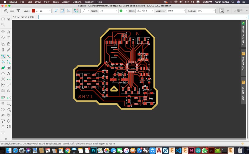
The base board above had enough for flex sensor. But this all was powered with 5V. Now my output valves and pump was rated 12V. Also Mosfets to run it. Instead of making new board and making it bigger, I wanted to keep it compact. Thus I decided to make a shield over it and power 12V seperately with DC Adapter. The I used N-gate mosfets to run each part. Thus I used 3 N-type mosfets.
MOSFET
The MOSFET (Metal Oxide Semiconductor Field Effect Transistor) transistor is a semiconductor device which is widely used for switching and amplifying electronic signals in the electronic devices. The MOSFET is a core of integrated circuit and it can be designed and fabricated in a single chip because of these very small sizes. The MOSFET is a four terminal device with source(S), gate (G), drain (D) and body (B) terminals. The body of the MOSFET is frequently connected to the source terminal so making it a three terminal device like field effect transistor. The MOSFET is very far the most common transistor and can be used in both analog and digital circuits.
The MOSFET can function in two ways : When there is no voltage on the gate, the channel shows its maximum conductance. As the voltage on the gate is either positive or negative, the channel conductivity decreases.
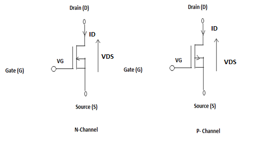
source : elprocus.com
When there is no voltage on the gate the device does not conduct. More is the voltage on the gate, the better the device can conduct.
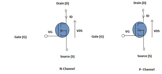
source : elprocus.com
Thus the transistor requires current whereas MOSFET require voltage. The driving requirement for the MOSFET is much better, much simpler as compared to a Transistor.
Learn More about mosfet using link below.
Baically mosfet is widely used for switching and amplifying electronic signals in the electronic devices.
This shoeld was made to save on space and also to run valves and motor seperately.
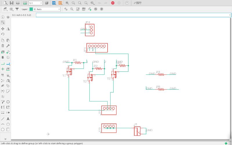
From above, you can see that I have used Three mosfets, In connection with a resistor. And have common Ground and VCC ( and has DC jack To power up through 12 V.)
Here comes the difficult part. Soldering and electronics were a big challenge for me through Fab Academy. I never had experience with electronics components and also no experience with soldering.
I never thought I would be able to solder so well (Ofcourse with many failures) with one hand. I am glad that I learned It through Fab Academy.
Below is the video showing the soldering process. So that others could refer from it and use my technique.
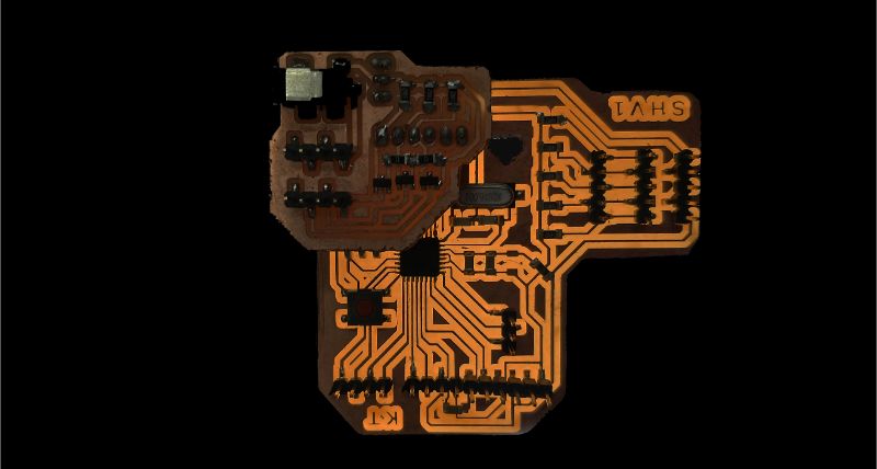
Soldered board with shield on it.
I struggled a lot. I had no electronic background. Thus it was very big challange. Also I had to find-out ways of soldering with one hand. Thus after week 7, started making iteration. I had lot of failurs.
I tried making many boards and Improved upon PCB design and soldering.
Image below shows image of all.
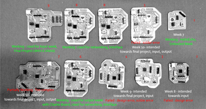
Sucessful Boards : Top Row
Failures include : (Bottom Row) : (1) Placement error, Soldering error. (2) Soldering error. (3-4) Design Error. (5) Design & Soldering error.
***Board Files and Schematics are attached thr button at the bottom of this page.
I started using flex sensor since week 11. I made my own flex sensor as well. You can go to my week 11 using button below and learn more about flex sensors.
The flex diagram is as below.
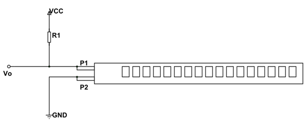
The R1 value could vary according to difference you want. Minimun is suggested at 10K Ohm.
A flex sensor has a range from about ~10K to ~35K, that means it won't give us a full 0-5 volt range (or 0-1023 analog value).
It performs better with 22K ohm Value resistor.
I used 22K Ohm as I wanted more range in values.
The code below is just to filter the value of flex sensor that above certain value it's output goes high.
Code
int flex = A0;


	void setup() {
	  // put your setup code here, to run once:
	  Serial.begin(9600);
	  pinMode(flex, INPUT);
	  pinMode(13,OUTPUT);

	}

	void loop() {
	  // put your main code here, to run repeatedly:
	  int a = analogRead(flex);
	  Serial.print(a);
	  Serial.println("flex");
	if(a > 100) // 250 for readymade flex sensor
	{
	  digitalWrite(13,HIGH);
	  delay(200);
	}
	else{
	  digitalWrite(13,LOW);
	  delay(100);
	}
	}
Video
Then I tried to measure the bend degrees of flex. You can see it below.
I used following code to run the flex sensor in Arduino IDE.
This code measures the resistence value and it maps the value in degrees with associated resistence.The serial monitor shows them.
	const int FLEX_PIN = A0; // Pin connected to voltage divider output

	// Measure the voltage at 5V and the actual resistance of your
	// resistor, and enter them below:
	const float VCC = 4.98; // Measured voltage of Ardunio 5V line
	const float R_DIV = 47500.0; // Measured resistance of 3.3k resistor

	// Upload the code, then try to adjust these values to more
	// accurately calculate bend degree.
	const float STRAIGHT_RESISTANCE = 22000.0; // resistance when straight, value of resistence
	const float BEND_RESISTANCE = 220000.0; // resistance at 90 deg - measure it using multimeter

	void setup()
	{
	  Serial.begin(9600);
	  pinMode(FLEX_PIN, INPUT);
	}

	void loop()
	{
	  // Read the ADC, and calculate voltage and resistance from it
	  int flexADC = analogRead(FLEX_PIN);
	  float flexV = flexADC * VCC / 1023.0;
	  float flexR = R_DIV * (VCC / flexV - 1.0);
	  Serial.println("Resistance: " + String(flexR) + "ohms");

	  // Use the calculated resistance to estimate the sensor's
	  // bend angle:
	  float angle = map(flexR, 0, BEND_RESISTANCE, 0, 90.0);
	  Serial.println("Bend: " + String(angle) + " degrees");
	  Serial.println();

	  delay(500);
	}
The video shows the resistence value and corresponding bend degree.
*For more information visit Input Week
I used a 12V DC pnuematic air pump and 2 - Two way solenoid valves for my output of final project.
You can find this 12V DC powered pump at any electrical shop or aquarium parts shop. The two way valves solenoid valves can be found at any pnuematic fitting store. Or you can see Bill of Materials at the bottom of page. The two way valves originally comes with 24V coil but you can get it replaced for 12V so that all three works on 12V power.
Why Two-Valves?
Here One valves opens when it is triggered to blow air. That time other one is closed. Then when it has to release air. Other valve opens and the first one closes.
The code below was to try the machanism of valves. The code one by one closes and opens valve.
Code
											int v1 = 8;
int v2 = 9;
void setup()
{
pinMode(v1,OUTPUT);
pinMode(v2,OUTPUT);
}

void loop()
{
  digitalWrite(v1,HIGH);
  digitalWrite(v2,LOW);
  delay(1000);
  digitalWrite(v2,LOW);
  digitalWrite(v1,LOW);
  delay(1000);


}
This code I used for my final project. This code filters the value of flex sensor. For example ,
Case 1 - Bending the fingers: If it goes beyond 315, it triggers that V1 will open and allow air to pass in. It also turns on motor to pump
Case 2- Coming back to normal state : If flex value goes below 300, it triggers that V2 will open and allow air to release out. It also turns off motor. Thus it wont pump air.
Code
		int flex = A0;
		int v1 = 10;
		int v2 = 9;
		int m = 8;
		void setup() {
		  Serial.begin(9600);
		  pinMode(flex,INPUT);
		  pinMode(v1,OUTPUT);
		  pinMode(v2,OUTPUT);
		  pinMode(m,OUTPUT);

		}

		void loop() {
		  int a = analogRead(flex);
		  Serial.println("flex");
		  Serial.print(a);
		  if (a >= 315)
		  { digitalWrite(m,HIGH);
			digitalWrite(v2,LOW);
			digitalWrite(v1,HIGH);
			delay(1000);
			digitalWrite(v1,LOW);

		  }
		  else if(a < 300)
		  {
			digitalWrite(m,LOW);
			digitalWrite(v1,LOW);
			digitalWrite(v2,HIGH);
			delay(1000);

		  }
		  else
		  {
			digitalWrite(m,LOW);
			digitalWrite(v1,LOW);
			digitalWrite(v2,LOW);
		  }

		}
Video
*Above video was tested on Arduino with Shield That I designed but then used above code to run with final board.
The entire project assembly hasvarious parts. I diveded entire assembly into 3 parts : 1. The Glove 2. Control Box.
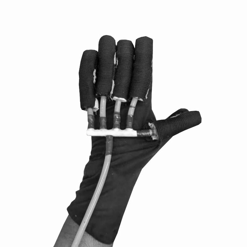
The image below shows final glove.
This contains : Purchased Cotton Glove, Modified with Velcro, Vaccume Pipes, 3D Printed Connectors, Baloons, 3D printed holder, Ribbed Plastic Hose Pipe. Fabric Finger.
First and essential part of glove is the actuator. Thus first I made the actuator. The process of the same is described below.
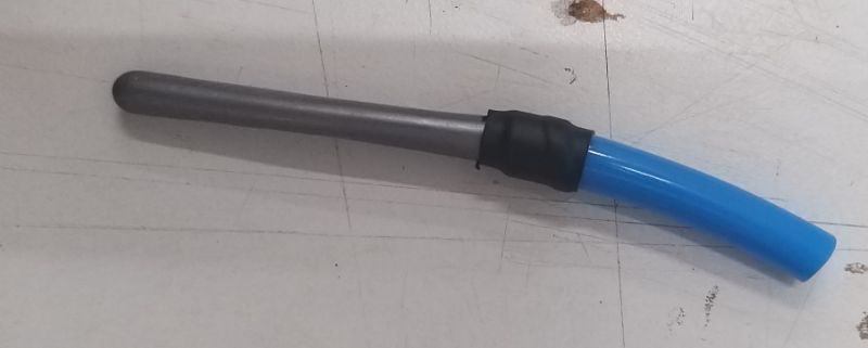
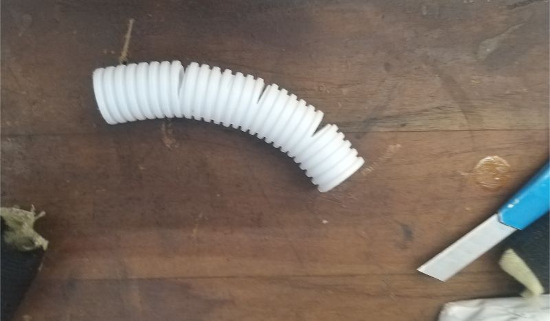
Making Soft Actuator
I made this soft actuator using a baloon and ribbed hose pipe. Pipe already have curvature. When you make cut slots in the regular rquired interval, it bends.
Thus it become a good bending actuator at enough pressure.
See it working as below :
Video
Why this Actuator?
Its easy to make, affordable, and good for prototyping.
How Did I improve It ?
I knew it would come out on the other end if not closed. Also baloon could blow out of slots.
Thus I ordered better baloons (Standard Latex 350Q Baloons). It has greater strength.
Covered it with Two Fabric finger cover.(Top part is made of flexible cloth and bottom is made of non-flexible fabric. Thus It only expands and bends in one direction.)
3D Printed Parts
I used 3D printing for below parts as it was not feasible to do with other processes.
1.Pipe Holder
I calculated diameter of pipe and made it accordingly.
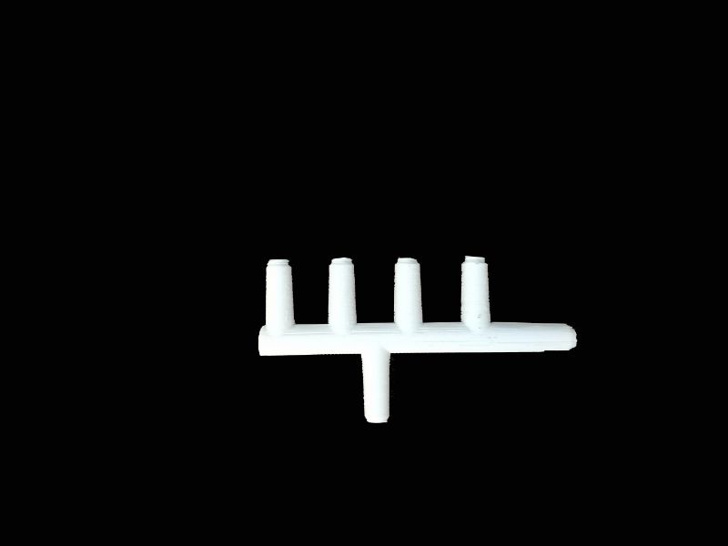
2. 5 to 1 & 2 to 1 : Pipe Connector
I calculated diameter of pipe and distance between holders made it accordingly.
Go to 3D Printing Week to know more about 3D printing.
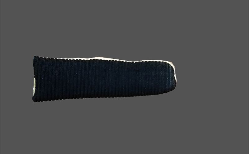
1. Mount Baloon on 8mm Vaccume Pipe.
2. Cut hose pipe (20mm) as required bending motion and mount over the baloon with 3d Printed holder. I locked it using HeatShrink Rubber.
3 A. As shown below connect the baloon, 3D printed holder and 3D Printed 6 way pipe connector (mentoned earlier) with 8mm pipes as below.
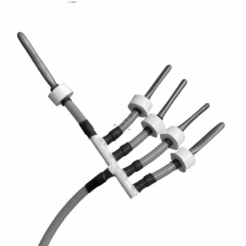
3 B. As shown below mount hose pipe over baloon and insert into the holder. It would look like below.
3 C. Then inserted into fabric finger pocket with velcro on bottom side. Which fixes on velecro on the cotton glove. (We can easily remove and mount it whenever we want.)
Then mount it on a cotton glove (or any) but dont forget to put negative part of velcro on it. Thus you'll get following type of structure.
The final glove will look as above.
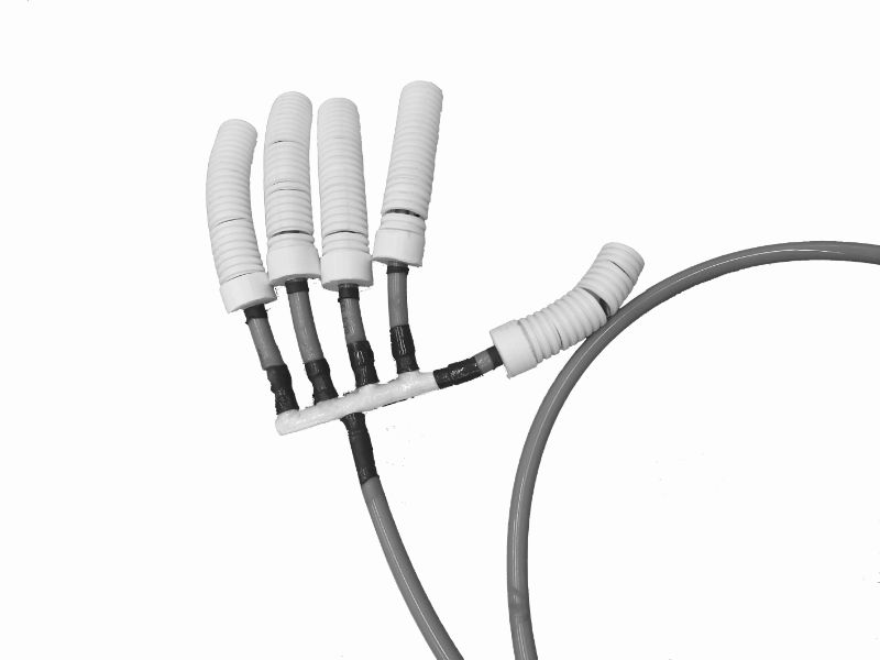
4. Then connect all pipes to 5 to 1 connector and connect that pipe to Control Box.
The control box contains everything that drives the project. This is like the heart and brain of the project. This assembly contains ; 1. Electronic Boards (Base and the shield) 2. 12V Two- 2-way valves. 3. One 12V DC Pnuematic Air pump. 4. Wires and pipes to connect.
All of the mentioned things are housed inside the box which I design and then fabricated using lasercut. The design was done taking in mind the portablity of the box. It shouldn't be heavy. And could be carried in a bag. Thus the final dimension came within 180 x 180 x 100 mm (approx). Which can be fitted in bagpack or purse or bag.
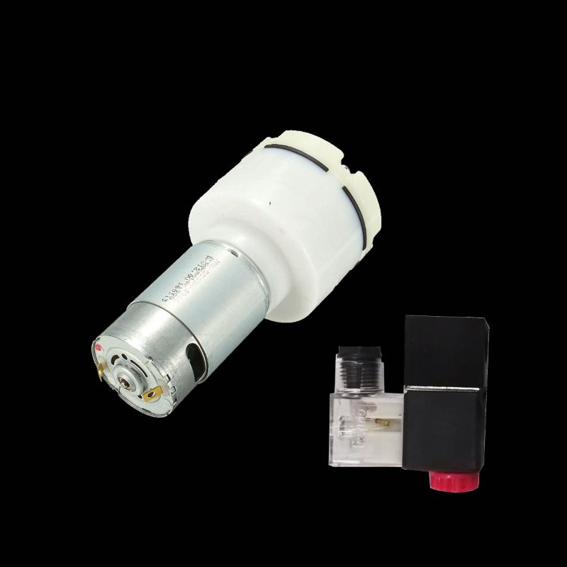
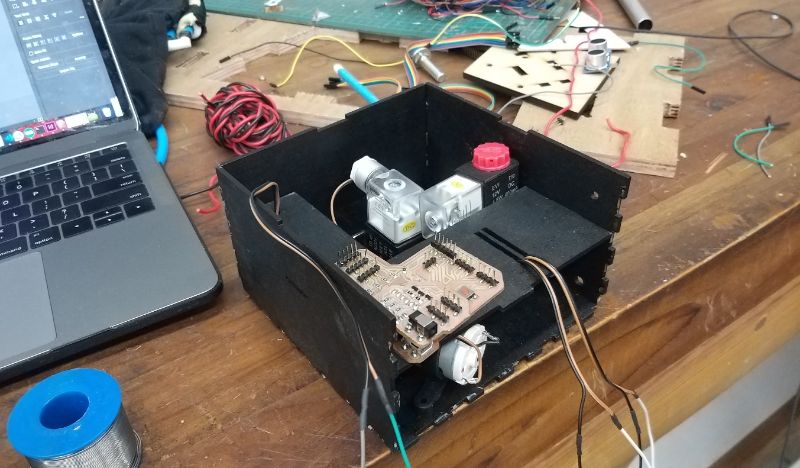
The image below shows : Two 2-way Solenoid Valves, 12V DC Air Pumps which takes major volume of the box.
Thus I made some models as I wanted to make it as compact as possible.
3D Modelling Attempts
I madevarious alternatives in fusion 360. And tried various kinds of arrangement and modelled the box. And tried to make it compact.
Final Box
(*Note : I removed curves then and modified .dxf file to make it better. Kurfing Didnt work well whileassembling laser cut part.)
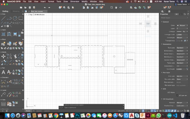
*The kerf was 0.2 mm thus I made male joint 0.1 mm bigger from both sides.
Parameters I used For cutting
| Material | Speed | Power |
| 3MM Pine MDF | 18 mm/sec | 50% |
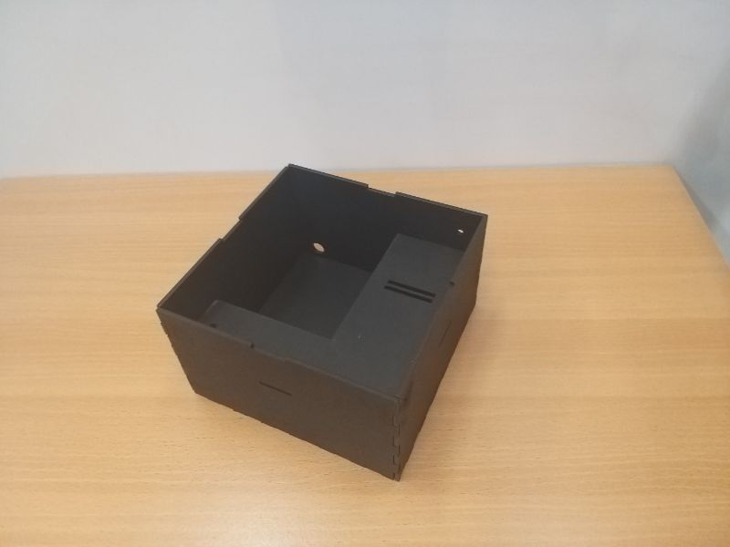
The image below shows the box after fabrication, paint and assembling :
Packaging the Control Box
The image below is from the stage where I was packing all components in the place.
After Packaging it the box will look as below.
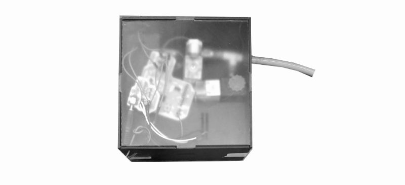
(*This image was taken while assembling.. The electronic board was kept in compartment above which is loose but then I fixed it when I was sure. So that it gets easier to remove. It is kept under semi transparant top plate so that you can se what is happenning inside.)
Connecting Flex sensor
In this project flex sensor is used to trigger the filling of air and releasing of air. For this project I used it in other hand finger. So that bending that finger could trigger movement in my other hand with glove.
Thus this completes the entire process of making box and the glove. The list below shows all the parts that I used and its vendor link.
The image below shows pinout of flex sensor.
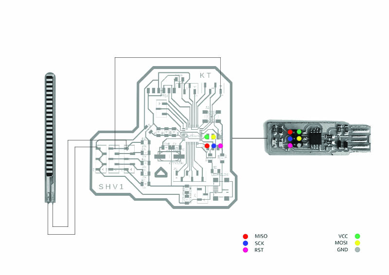
Then you can put flex sensor into other hand finger glove and use it as controller.
***The triangular hole in the board is to orient as well as to fix the board in place with positive part in box.
It is really difficult to know how much you actually need to do and how much time it will take. Thus its better to be early than being late and suffer.
As it is said 'Everything that is supposed to go wrong will definately go wrong.'
First thing first : 1. Set your spirals. You need to be atleast sure about what do you want to do at inital stage and go in one direction.
2. Get to know the components you would use with final project and work with it at early stage.
3. I realised the more you know your parts more you'll understand complexity of project.
4. Document as you go, so you dont have to rush in last minute.
1. First thing went wrong was sourcing time. I should have ordered earlier and explored it more. It arrived just in Mechanical Design Week. That two weeks went off very fast and didnt get to try more stuff.
2. Another was to divide time. I didn't divide time wisely according to complexity.
3. Pnuematics is complex than it seems. I used 3D printed parts as connectors. But I realised it was never air tight. I had to seal it with epoxy coat.
I tried various other actuators and material. In my case it didnt perform well. Also in this case type of baloon used matters.
I found out heavy duty latex baloon and those worked better compared to other.
My strategy was to go in spiral developement. The initial strategy was in 4 spirals and complete atleast 2-3. Then we can build on it.
Spiral 1. Making One finger actuator work. Making one beding actuator. And testing manually. - Done
Spiral 2. Making 5 actuator, integrating with glove and combinging it and operating it. - Done
Spiral 3. Operating Mechanism with flex sensor and packaging it.- Done
Spiral 4. Adding more functionalities if get completes in time. - Future Add On
I managed to make bending actuators. Under enough presssure it gives fairly OK performance.
It could bend slightly fingers.Thus there is scope for improvemt after fab academy.
The integration of flex with valves worked nicely and responds very accurately,
I would like to add more functionality and more strenth to it in future.
I observed that It performs fairly OK with enough pressure. But It has room for enhancement with various iteration and changes.
It could be further detailed out and developed.
In next version I could add more flex sensors and more valves (But it will be very heavy) to control each finger seperately.
I can even integrate flex sensors in the same glove. (That might not help in all case of rehab as intended.)
Out of this project new projects like guesture to text communication glove could be made. Which will help people with speech problem to communicate.
Through the process of final project making I learned that, there are minute details we need to keep in mind while making anything.
I understood that you've to go through varios trial and errors to achive a solution.
Sometimes It may happen that things wont be in your favour, but you need to be patience and keep learning.
I learned how to integrate various parts and processes and package them into one system.
It takes lot of effort to integrate them into one system and make a beautiful system, as each of them has its own properties.
| Components | Vendor Link | Cost(70 INR~1$) |
| Fabric : Flexible | Souced Locally | 100-150 INR/Mtr. |
| Fabric : Non-Flexible | Souced Locally | 70-100 INR/Mtr. |
| Fabric Cotton Glove | ~250 INR | |
| Main Final Board and Shield- AtMega328p, Copper board, Capacitors, Resistors,, Mosfets, LEDs etc. | Fabricated At FabLab |
*Visit The board design section in the Final Project Development Page for components. |
| Flex Sensors | Can be made/purchased at : Amazon | 500-600 INR/Piece |
| Solenoid Air-Valve (Two Way) | Amazon | 300~350 INR/Piece |
| Pnuematic Air Pump (12V-DC) | Amazon | 300~400 INR/Piece |
| Ribbed Plastic Hose | Vendor Site | 35~50 INR/Mtr |
| 8MM Vaccume Pipe | Vendor Site | 30~35 INR /Mtr |
| 3MM Pine MDF - A1 Sheet | Sorced Locally | INR 140~200 |
*I also used 3D Printed and Lasercut parts.
*Licence that I used is attached at the end of page.
*I have attached all files on link at the end of page.

