14. Networking and communications
Design, build, and connect wired or wire
Visit Group website for more information. Click here.
COMMUNICATIONS AND NETWORKING
-
This week’s task was to design and build a wired or wireless network connecting at least 2 or more board.
-
I had to start from the very beginning and understand what is networking and what is serial and parallel communications.
-
After a little research, I came to find 2 nice links that explain the basics:
- TCP IP guide: Networking Fundamentals.
Implementation:
What Is I2C(Inter-Integrated Circuit bus)?
-
It is a two-wire synchronous serial bus. Let’s take a look at what each of those words means:
-
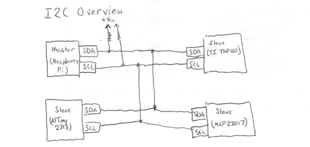
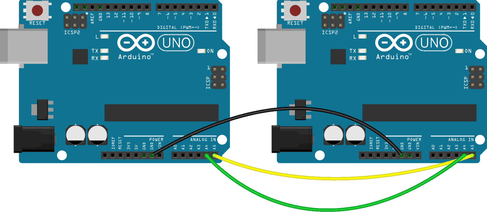
Two wire - This one’s easy, I2C uses two wires (in addition to ground, of course!) They’re called SDA (serial data) and SCL (serial clock). These are wired in an open-drain configuration, which means that the outputs of all connected devices cannot directly output a logic-level 1 (high) and instead can only pull low (connect to ground, outputting a 0). To make the line go high, all devices release their pull on the line and a pull-up resistor between the line and the positive rail pulls the voltage up.
-
There is one pull-up resistor on SDA and one on SCL.
 - Synchronous - This means that data transfer is synchronized via a clock signal that is present to all connected devices. This is generated by the master. To contrast, an asynchronous serial system does not have a clock signal. Instead, it uses a pre-determined time-base, or baud rate.
-
Serial - Data transferred serially means that one single bit is transferred at a time over a single wire. To contrast, parallel data transfer has multiple wires, each carrying one bit, which are all sampled at once to transfer multiple bits in parallel.
-
Bus - A bus is a system which allows many devices to communicate to each other over a single set of wires. While it may be called a bus, USB is not a true bus at the hardware level, as connecting multiple devices requires a hub. A bus such as I2C allows new devices to be added simply by attaching their SDA and SCL connections to the existing line. Busses (I2C, USB, PCI, etc) all use an addressing system, in which each device has a unique address. An address in this case is simply a binary number, and all messages to that device must be sent with that address.
-
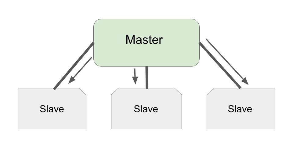
On an I2C bus, there are masters and there are slaves. A master initiates a connection while a slave must wait for a master to address it before it sends or receives anything. I2C has multi-master capability, which means that more than one master may exist, and if two masters attempt a transmission at the same time, they must perform arbitration to correct the problem. This tutorial will not cover multi-master configurations, but it should be noted that they do exist.
-
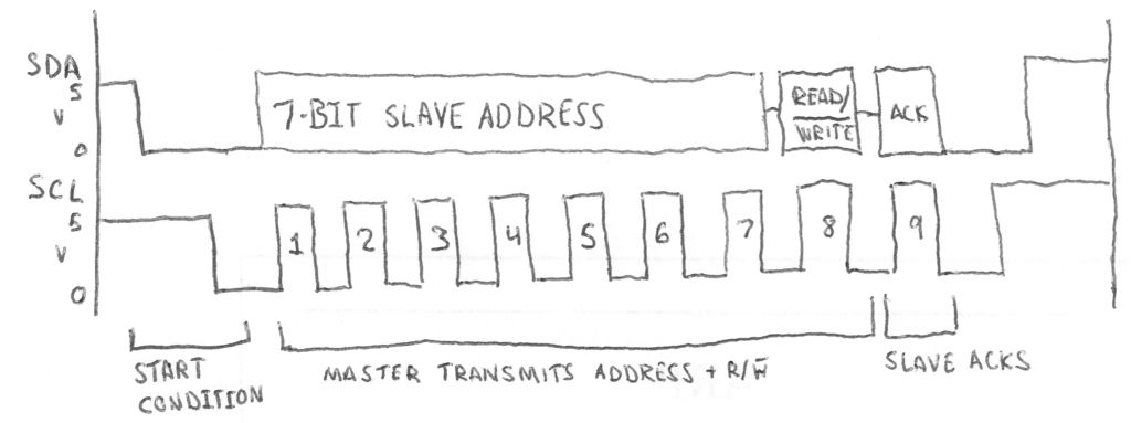
That basically covers the I2C protocol itself, in that a master can initiate a read or a write, and transfer continues until the master sends a stop condition. When the master is reading from a slave, it will issue a NACK instead of an ACK on the last byte, before the stop condition, to indicate that it is done receiving.
-
On some I2C devices (or should I say most, it’s very common), the access protocol is set up as a register bank. To read or write from these registers, you must first write an internal address which is the address of the register you wish to read or write. After writing an internal address, you may read or write multiple bytes and the internal address will increment with each byte. This is the preferred protocol for almost all I2C memory devices as well as most sensors and I/O expanders.
Note
The USI hardware has three pins:
-
DO - Data Output, used for three-wire (SPI) communication mode only
-
DI/SDA - Data Input/Serial Data, used as SDA in I2C configuration
-
USCK/SCL - Clock, used as SCK in I2C configuration
In addition, the USI hardware has three registers:
-
USIDR - USI Data Shift Register - Shifts data in and out of the USI hardware
-
USISR - USI Status Register - Has state flags and 4-bit counter
-
USICR - USI Control Register - Has interrupt enables, clock modes, and software clock strobe functions
For this task, my boards would have to support both I2C modes, being able to operate as both a slave and a master depending on serial port operations. Knowing very little about the USI hardware and only slightly more about the I2C protocol in general, I set out to master the I2C protocol, to make it my slave and command it to do my data transmissions. And that I did, and it worked well for the project.
Master Code stability:
And That was it!
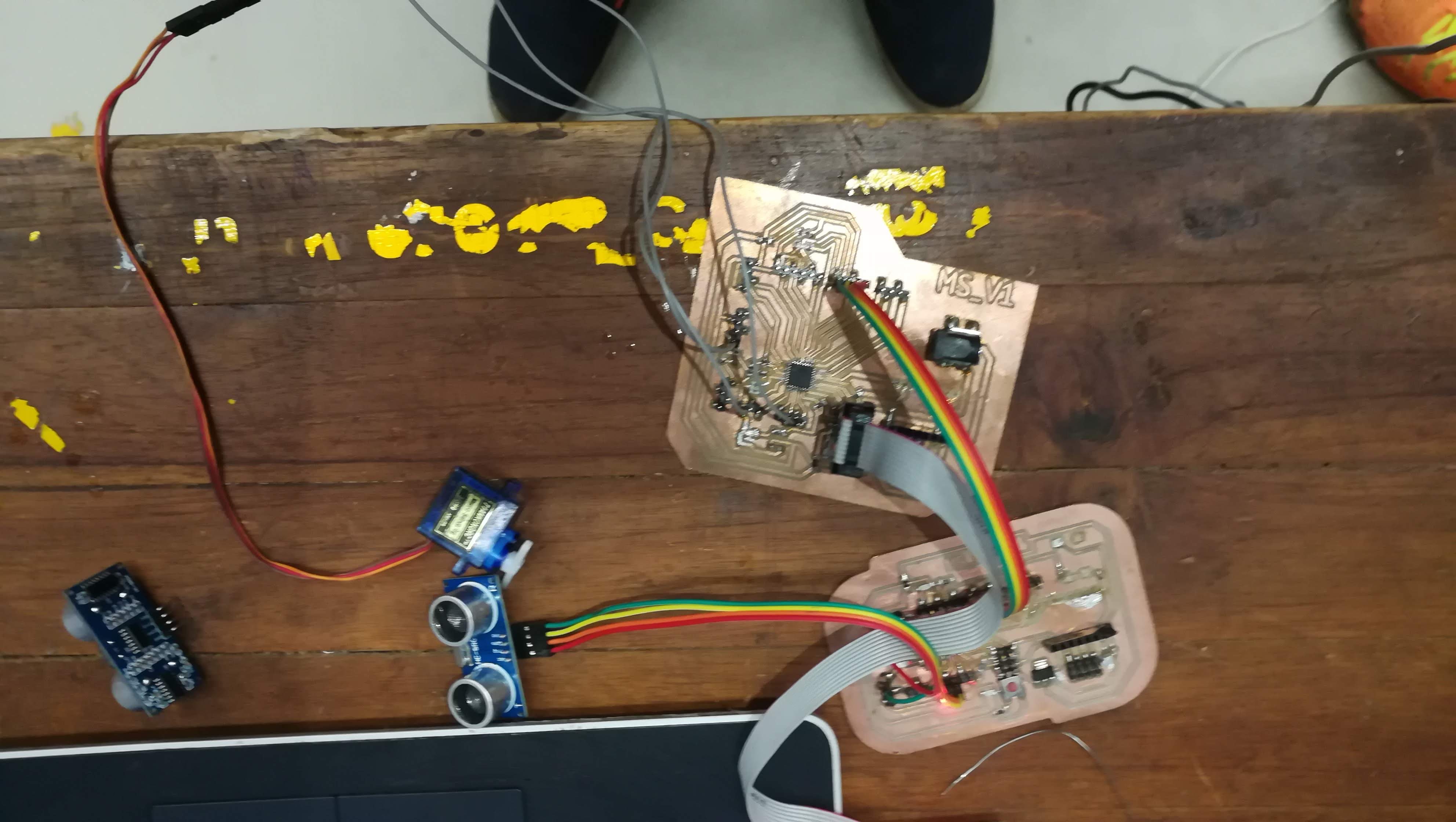
These includes two boards (i.e 328p) where one of those sends signal to another and other one replies by acknowledging the signal. Hence two way communication works.
The board 1 includes the components like ultrasonic (input sensor) and in second board there is servo motor. After getting the input in ultrasonic present at board 1, the servo motor at board 2 starts functioning and the signal(acknowledgement) is shown in board 1 in terms of LED blinking.
Master Code
#include <Wire.h>  //This includes wire library of arduino.
#include <Ultrasonic.h>
Ultrasonic ultrasonic(7,8);
int distance;


void setup() {
  Serial.begin(9600);
  Wire.begin();
   pinMode(13, OUTPUT);
}

void loop() {
  distance = ultrasonic.read(); //Reads the ultrasonic distance

  Serial.print("Distance in CM: ");
  Serial.println(distance); //Displays on the serial monitor
  if (distance <= 25)

digitalWrite(13, LOW);
    Wire.beginTransmission(8); //slave number 8
    Wire.write(1);
    Wire.endTransmission();
    delay(200);

  else

    digitalWrite(13, HIGH);
    Wire.beginTransmission(8); //slave number 8
    Wire.write(0);
    Wire.endTransmission();
    delay(200);

}
Slave code
#include <Wire.h> //This includes wire library of arduino.
#include <Servo.h> //This include servo library

Servo myservo;
int d1 = 0;
int pos = 0;

void setup() {
  myservo.attach(9);
  pinMode(13, OUTPUT);
  Serial.begin(9600);
  Wire.begin(8);     //change address
  Wire.onReceive(recieveEvent);
}

void loop() {

  if (d1 == 1)

    digitalWrite(13, HIGH);
    myservo.write(180);
    delay(1000);
    myservo.write(0);
    delay(1000);
  } else if (d1 == 0)

    digitalWrite(13, LOW);
    myservo.write(0);
  } else


  delay(200);
}


void recieveEvent(int howMany)
{
  while (Wire.available())

    d1 = Wire.read();//reads the transmitted byte

}
Embedded Networking and Communications
-
Here we have to design and build network which commnicate with other, in other sense we can also say that communication between master and slave.
-
For that i have my two board of 328p :MSv1 and MSv2.
- Here i am using I2C communication that would be work on protocols
- Here my board can communicate with each other and also communicate in topology.
- Afterwards there is a question when i communicate with that board it only shows blinking thats a huge question for my assessment.
- Then i decided to use sensor on end boards, For my master i am using ultrasonic and for slave i am using servo motor
This statement clear all question and doubt!
- This week was different with input and output week for me , one good thing was i have my 2 board which has input pins and output pins for sensor, and best thing as that my board have I2C pins. Overall i gathered good amount of information in I2C
Master and slave board files - Containing files (.prj,sch,.brd)